Table of Contents
Advertisement
Quick Links
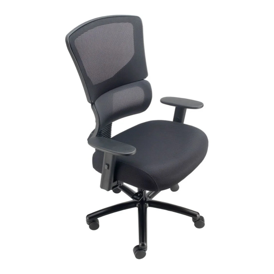
ASSEMBLY INSTRUCTIONS
ITEM NO.: 695643 / 695643L
Part List
Key
Description
Qty.
Part
A
CASTERS
5
B
BASE
1
SEAT CUSHION
1
C
RIGHT
D
1
ARMREST
LEFT
1
E
ARMREST
ARMREST
F
8
SCREWS
D 1/4" x L 1"
G
MECHANISM
1
MECHANISM
SCREWS
H
4
D 5/16" x L 1"
1
I
BACK SUPPORT
BACK SUPPORT
J
SCREWS
3
D 5/16" x L 5/8"
K
ALLEN WRENCH
1
L
GAS LIFT
1
Step 1
Turn Base "B" upside down.
Insert Casters "A" into Base "B".
A
B
Step 4
Attach Back Support "I" to the rear of Mechanism "G"
with Back Support Screws "J".
NOTE: Fully tighten all screws.
K
x 3
J
G
I
ATTENTION: Make certain that all screws are fully tightened before using chair.
Lubricate all moving parts and tighten all screws every 6 months or as needed.
Step 2
Attach Right Armrest "D" to Seat Cushion "C" with
Armrest Screws "F". Repeat for Left Armrest "E".
NOTE: Arrows on armrests point to
front of seat cushion and fully tighten all screws.
K
x 5
F
x 4
F
D
C
Step 5
Insert Gas Lift "L" into hole on Base "B".
L
B
Step 3
Attach Mechanism "G" to Seat Cushion "C" with
Mechanism Screws "H".
NOTE: Fully tighten all screws.
K
x 4
x 4
H
G
E
C
Step 6
Place seat assembly onto Gas Lift "L". Push firmly
on the chair seat to securely attach seat assembly to
seat post.
L
Advertisement
Table of Contents

Related Manuals for interion 695643


Summary of Contents for interion 695643
- Page 1 ASSEMBLY INSTRUCTIONS ITEM NO.: 695643 / 695643L Step 1 Step 2 Step 3 Part List Turn Base “B” upside down. Attach Right Armrest “D” to Seat Cushion “C” with Attach Mechanism “G” to Seat Cushion “C” with Description Qty. Part Insert Casters “A”...
- Page 2 CONTROL INSTRUCTIONS ITEM NO.: 695643 / 695643L BACK HEIGHT ADJUSTMENT Slowly raise the chair back until it clicks and locks in position. You can keep raising the chair back in increments until you get the chair back to the preferred height.
Need help?
Do you have a question about the 695643 and is the answer not in the manual?
Questions and answers