Table of Contents
Advertisement
Quick Links
Advertisement
Table of Contents

Related Manuals for AXIOMTEK NA592 Series


Summary of Contents for AXIOMTEK NA592 Series
- Page 1 NA592 Series SMB Network Appliance User’s Manual...
-
Page 2: Disclaimers
Axiomtek does not make any commitment to update the information in this manual. Axiomtek reserves the right to change or revise this document and/or product at any time without notice. No part of this document may be reproduced, stored in a retrieval system, or transmitted, in any form or by any means, electronic, mechanical, photocopying, recording, or otherwise, without the prior written permission of Axiomtek Co., Ltd. -
Page 3: Safety Approvals
Safety Approvals ◆ CE Marking ◆ FCC Class A ◆ FCC Compliance This equipment has been tested and complies with the limits for a Class A digital device, pursuant to Part 15 of the FCC Rules. These limits are designed to provide reasonable protection against harmful interference in a residential installation. -
Page 4: Safety Precautions
Most electronic components are sensitive to static electrical charge. Disconnect the power cords from the NA592 Series before making any installation. Be sure both the system and the external devices are turned OFF. Sudden surge of power could ruin sensitive components. Make sure the NA592 series is properly grounded. -
Page 5: Table Of Contents
Table of Contents Disclaimers ..................... ii Safety Approvals ................... iii Safety Precautions ..................iv Section 1 Introduction .......... 1 General Description ................1 Feature ....................1 Specifications ..................2 Dimensions and Outlines ..............5 I/O Outlets .................... 6 1.5.1 Front Panel ....................6 1.5.2 Rear Panel .................... - Page 6 2.4.15 FAN Connectors (FAN1~FAN3) ..............25 2.4.16 Serial ATA Connectors (SATA1 & SATA2) ..........25 2.4.17 USB2.0 Port Connector (USB1) ..............26 2.4.18 VGA pin header (VGA1) ................26 Hardware Installation ................ 27 2.5.1 Installing the CPU..................27 2.5.2 Installing the Memory ................28 2.5.3 Installing the Hard Disks ................
-
Page 7: Introduction
NA592 Series User’s Manual Section 1 Introduction This chapter contains general information and detailed specifications of the NA592 Series Network Appliance Server. It contains the following sections: ◼ General Description ◼ Features ◼ Specifications ◼ Dimensions and Outlines ◼ I/O Outlets General Description The NA592 is a 1U rackmount network appliance based on Intel®... -
Page 8: Specifications
NA592 Series User’s Manual Specifications System ⚫ System CPU ◼ Intel® Comet Lake Xeon® Processor W1200 Family and 10th Core i7/i5/i3 processors ⚫ System Chipset ◼ Intel® W480E ⚫ System Memory ◼ 4 x DDR4 2933 DIMM sockets, up to 128GB none-ECC / ECC memory ⚫... - Page 9 NA592 Series User’s Manual ⚫ LAN Modules Slim Module Ports Chipset Bypass NA592 GbE Copper Modules AX93316-8GI Intel i350 AX93316-8GIL Intel i350 AX93326-8GIL Intel 210AT AX93336-4GI Intel i211AT AX93336-4GIL Intel i350 GbE Fiber Modules AX93322-8FI Intel i350 AX93322-8MIL Intel i350...
- Page 10 NA592 Series User’s Manual ⚫ Power Supply ◼ 300W single power supply in default/400W single power supply by project ◼ 400W redundant power supply (1+1) Note: Indicates to unplug all AC power cord(s) to disconnect AC Power ⚫ OS Compatibility ◼...
-
Page 11: Dimensions And Outlines
NA592 Series User’s Manual Dimensions and Outlines The following diagram shows you dimensions and outlines of the NA592 Series. Default: 10 LAN ports max up to 26 LAN ports Introduction... -
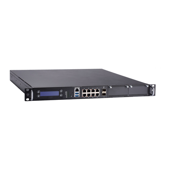
Page 12: I/O Outlets
NA592 Series User’s Manual I/O Outlets Locate front and rear panel I/O outlets on the NA592 Series server to connect serial and ethernet interface devices. 1.5.1 Front Panel ⚫ Power LED (Green) LED light up when the server is powered on to perform diagnostic tests and proper operation checking. - Page 13 NA592 Series User’s Manual ⚫ Transfer Rate for LAN port The double-color LED light indicates 10/100/1000Mbps transfer rate. LED Light Color Transfer Rate Dark 10Mbps Green 100Mbps Orange 1000Mbps ◼ If the LED is dark and Active/Link LED is lighting on flashing, the transfer rate should be 10Mbps.
-
Page 14: Rear Panel
NA592 Series User’s Manual 1.5.2 Rear Panel ⚫ Power Supply System power use power cord to connect the power supply to electrical outlet (AC). ⚫ System Fans These are fans for cooling down system temperature. ⚫ VGA port This item is for optional, not include into BOM. -
Page 15: Hardware And Installation
⚫ SATA cable x 2 for 2.5” SATA HDDs If you cannot find this package or any items are missing, please contact Axiomtek distributors immediately. If you order any optional components, the package might contain those additional hardware or documents accordingly. -
Page 16: Board Layout
NA592 Series User’s Manual Board Layout Hardware and Installation... - Page 17 NA592 Series User’s Manual BOTTOM Hardware and Installation...
-
Page 18: Jumper Settings
And remove jumper clip from 2 jumper pins to open. Below illustration shows how to set up jumper. This section provides the information about jumpers and connectors of NA592 Series. Properly configure jumper settings on the main board in this appliance to meet your application purpose. -
Page 19: Rtc/Cmos Clear Jumper (Jp1)
NA592 Series User’s Manual 2.3.1 RTC/CMOS Clear Jumper (JP1) Description Function Jumper Setting Normal (Default) RTC/COMS Clear Clear RTC/CMOS 2.3.2 TACT SW1 Function Selection Jumper (JP3/Lower Button) Description Function Jumper Setting Power On/Off TACT SW1 Function Selection GPIO Reset (Default) -
Page 20: Lan Bypass Control Jumper (Jp6/Jp7/Jp9)
NA592 Series User’s Manual 2.3.3 LAN Bypass Control Jumper (JP6/JP7/JP9) Use this jumper to select the LAN Bypass Function. Description Function Jumper Setting All SEG. Bypass as same as Power Off status LAN Bypass Trigger All SEG Bypass Disable when Power On... -
Page 21: Crt Always On (Jp10)
NA592 Series User’s Manual 2.3.5 CRT always on (JP10) Description Function Jumper Setting CRT Always On disable JP10 CRT always on CRT Always On enable (Default) JP10 2.3.6 Auto Power Button Model Jumper (JP12) Description Function Jumper Setting JP12 Always Power off... -
Page 22: Connectors
NA592 Series User’s Manual Connectors Signals go to other parts of the system through connectors. Loose or improper connection might cause problems, please make sure all connectors are properly and firmly connected. Here is a summary table which shows all connectors on the hardware. -
Page 23: Atx 2*4 Pin +12V Cpu Power Connector (Atx1)
NA592 Series User’s Manual 2.4.1 ATX 2*4 pin +12V CPU Power Connector (ATX1) +12V power supplied to CPU on the board by connecting the power connector. Please make sure all components and devices are properly installed before connecting the power connector. We recommend connecting both ATX1 and ATX2 to board at the same time to adequately provide power. -
Page 24: Atx 24 Pin Power Connector (Cn1)
NA592 Series User’s Manual 2.4.4 ATX 24 pin Power Connector (CN1) Steady and sufficient power can be supplied to all components on the board by connecting the power connector. Please make sure all components and devices are properly installed before connecting the power connector. -
Page 25: E-Key 2230 (Cn3)
NA592 Series User’s Manual 2.4.6 M.2 E-key 2230 (CN3) Signal Signal Ground (GND) +3.3V USB_D+ +3.3V USB_D- Ground (GND) Ground (GND) Ground (GND) Ground (GND) Wake_N M.2 E-Key Ground (GND) PCIE _TX_P PCIE _TX_N Ground (GND) PCIE _RX_P PCIE _RX_N... -
Page 26: B-Key 2242 (Cn4)
NA592 Series User’s Manual 2.4.7 M.2 B-key 2242 (CN4) Signal Signal +3.3V Ground (GND) +3.3V Ground (GND) USB_D+ USB_D- SATA_LED Ground (GND) M.2 B-Key Ground (GND) Ground (GND) Ground (GND) SATA_RX_P SMBCLK SATA_RX_N SMBDAT Ground (GND) SATA_TX_N SATA_TX_P Ground (GND) -
Page 27: Mini Card Connector (Cn5)
NA592 Series User’s Manual 2.4.8 Mini Card Connector (CN5) This is a 52-pin connector which has two sku. One is PCIeX1 and USB2.0. Another is SATA and USB2.0. The sku is fixed and cannot be changed after shipment. Signal Signal WAKE_N +3.3... -
Page 28: Lcm Connector (Cn6)
NA592 Series User’s Manual +3.3V 2.4.9 LCM Connector (CN6) This is a 5-pin connector for LCM. Signal RX (co-lay COM2) TX (co-lay COM2) Ground (GND) 2.4.10 1X2 SFP Connector (CN7) Signal Signal Ground (GND) Ground (GND) TX_Fault TX_Fault TX_Disable TX_Disable... -
Page 29: Usb3.0 And Console Connector (Cn9)
NA592 Series User’s Manual Down Fiber Port: Link Up Fiber Port: Link 2.4.11 USB3.0 and console Connector (CN9) Signal Signal USB_POWER USBP2N USBP2P Ground (GND) SSRX2N SSRX2P Ground (GND) SSTX2N SSTX2P USB_POWER USBP1N USBP1P Ground (GND) SSRX1N SSRX1P Ground (GND) -
Page 30: Front Panel Bezel Connector (Cn11)
NA592 Series User’s Manual 2.4.13 Front Panel Bezel Connector (CN11) Power LED: This 3-pin connector (Pin 1, 3, 5) connects a LED indicator to the system power switch on the case. Pin 1 is assigned as +, and Pin 3, Pin 5 as -. The Power LED lights up when the system is powered ON. -
Page 31: Digital Input/Output Connector (Dio1)
NA592 Series User’s Manual 2.4.14 Digital input/output Connector (DIO1) Signal Signal Ground (GND) Ground (GND) GPO3 GPI3 GPO2 GPI2 GPO1 GPI1 DIO1 GPO0 GPI0 2.4.15 FAN Connectors (FAN1~FAN3) System fans are always needed to cool down CPU and system temperature. FAN1~FAN3 connectors provide power to these system fan. -
Page 32: Usb2.0 Port Connector (Usb1)
NA592 Series User’s Manual 2.4.17 USB2.0 Port Connector (USB1) The 10-pin standard Universal Serial Bus 2.0(USB2.0) connector on this board is for installing versatile USB interface peripherals. Signal Signal USB_POWER USB_POWER USB_P1_DN USB_P2_DN USB_P1_DP USB_P2_DP Ground (GND) Ground (GND) USB1... -
Page 33: Hardware Installation
NA592 Series User’s Manual Hardware Installation This section provides information of how to install the NA592 Series. 2.5.1 Installing the CPU ® Before installing the processor, please access Intel website for more detail information of Processor Integration Video (LGA1200): https://www.intel.sg/content/www/xa/en/support/products/873/processors.html The LGA1200 processor socket comes with a cover to protect the processor. -
Page 34: Installing The Memory
NA592 Series User’s Manual 2.5.2 Installing the Memory The board supports four DDR4 UDIMM memory sockets with maximum memory capacity up to 128GB. Please follow steps below to install the memory modules: Push down latches on each side of the DIMM socket. -
Page 35: Installing The Hard Disks
NA592 Series User’s Manual 2.5.3 Installing the Hard Disks The system supports or two 2.5” HDDs or one 3.5” HDD. Two 2.5” HDD ⚫ One 3.5” HDD ⚫ Hardware and Installation... - Page 36 NA592 Series User’s Manual This page is intentionally left blank. Hardware and Installation...
-
Page 37: Ami Bios Setup Utility
NA592 Series User’s Manual Section 3 AMI BIOS Setup Utility The AMI BIOS provides users with a built-in setup program to modify basic system configuration. All configured parameters are stored in a battery-backed-up RAM (CMOS RAM) to save the setup information whenever the power is turned off. This chapter provides users with detailed description about how to set up basic system configuration through the AMI BIOS setup utility. -
Page 38: Main Menu
NA592 Series User’s Manual Main Menu When you first enter the setup utility, you will enter the Main setup screen. You can always return to the Main setup screen by selecting the Main tab. System Time/Date can be set up as described below. -
Page 39: Advanced Menu
NA592 Series User’s Manual Advanced Menu The Advanced menu also allows users to set configuration of the CPU and other system devices. You can select any of the items in the left frame of the screen to go to the sub menus: ►... - Page 40 NA592 Series User’s Manual ⚫ CPU Configuration This screen shows the CPU Configuration, and you can change the value of the selected option. AMI BIOS Setup Utility...
- Page 41 NA592 Series User’s Manual ⚫ PCH-FW Configuration You can use this screen to select options for the PCH-FW Configuration, and change the value of the selected option. A description of the selected item appears on the right side of the screen.
- Page 42 NA592 Series User’s Manual ⚫ Trusted Computing This item supports security devices. “Enable” or “Disable” BIOS support for security devices. If you installed the Security device, such as TPM, you could see the following information for the TPM device and status.
- Page 43 NA592 Series User’s Manual ⚫ NCT6102D Super IO Configuration You can use this screen to select options for the NCT6102D Super IO Configuration, and change the value of the selected option. A description of the selected item appears on the right side of the screen.
- Page 44 NA592 Series User’s Manual AMI BIOS Setup Utility...
- Page 45 NA592 Series User’s Manual ➢ Serial Port 2 Configuration This option specifies the base I/O port address and Interrupt Request address of serial port 2. The Optimal setting is 2F8h/IRQ3. AMI BIOS Setup Utility...
- Page 46 NA592 Series User’s Manual ⚫ NCT6102D H/W Monitor This screen monitors are hardware health. AMI BIOS Setup Utility...
- Page 47 NA592 Series User’s Manual This screen displays the temperature of system and CPU, cooling fan speed in RPM and system voltages (VCORE, +5VSBV and +5V). AMI BIOS Setup Utility...
- Page 48 NA592 Series User’s Manual ⚫ Serial Port Console Redirection ➢ Console Redirection Use this item to enable or disable console redirection. The settings specify how the host computer and remote computer (which the user is using) will exchange data. Both computers should have the same or compatible setting.
- Page 49 NA592 Series User’s Manual Terminal Type This item allows you to select the target terminal type. Configuration options: ANSI, VT100, VT100+ and VT-UTF8. Bits per second This item allows you to setup the data transfer rate for the console port. The default value is 115200.
- Page 50 NA592 Series User’s Manual Flow Control This item allows you to select flow control for console redirection. The configuration options: None and Hardware RTS/CTS. VT-UTF8 Combo Key Support Use this item to Enabled and Disabled VT-UTF8 combination key supports for ANSI / VT100 terminals.
- Page 51 NA592 Series User’s Manual USB Mass Storage Driver Support Enable this field USB can be storage. This should be enabled this field. AMI BIOS Setup Utility...
- Page 52 NA592 Series User’s Manual ⚫ Network Stack Configuration For Network stack, use Network item to “Disabled” or “Enabled” mode. AMI BIOS Setup Utility...
- Page 53 NA592 Series User’s Manual ⚫ NVMe Configuration This screen shows the NVMe Configuration, and you can see the NVMe controller and drive information. AMI BIOS Setup Utility...
- Page 54 NA592 Series User’s Manual ⚫ LBP @PowerOn (All SEG) For Power On LAN Bypass setting, use LBP @PowerOn item to “Disabled”, “Enabled” or “Last State” for LAN Bypass all segments. ⚫ LBP @Power Off (All SEG) For Power off LAN Bypass setting, use LBP @PowerOff item to “Disabled”, “Enabled” or “Last State”...
-
Page 55: Chipset Menu
NA592 Series User’s Manual Chipset Menu The Chipset menu allows users to change the advanced chipset settings. You can select any of the items in the left frame of the screen to go to the sub menus: ► System Agent (SA) Configuration ►... - Page 56 NA592 Series User’s Manual ⚫ System Agent (SA) Configuration ➢ Memory Configuration This screen allows users to configure parameters of North Bridge Chipset. AMI BIOS Setup Utility...
- Page 57 NA592 Series User’s Manual ⚫ PCH-IO Configuration AMI BIOS Setup Utility...
- Page 58 NA592 Series User’s Manual AMI BIOS Setup Utility...
-
Page 59: Security Menu
NA592 Series User’s Manual Security Menu The Security menu allows users to change the security settings for the system. ⚫ Administrator Password This item indicates whether an administrator password has been set. If the password has been installed, Installed displays. If not, Not Installed displays. -
Page 60: Boot Menu
NA592 Series User’s Manual Boot Menu The Boot menu allows users to change boot options of the system. ⚫ Setup Prompt Timeout AMI BIOS Setup Utility... -
Page 61: Save & Exit Menu
NA592 Series User’s Manual Save & Exit Menu The Save & Exit menu allows users to load your system configuration with optimal or fail-safe default values. ⚫ Save Changes and Exit When you have completed the system configuration changes, select this option to leave Setup and return to Main Menu. - Page 62 NA592 Series User’s Manual ⚫ Discard Changes and Exit Select this option to quit Setup without making any permanent changes to the system configuration and return to Main Menu. Select Discard Changes and Exit from the Save & Exit menu and press <Enter>. Select Yes to discard changes and exit.
- Page 63 NA592 Series User’s Manual ⚫ Discard Changes and Reset Select this option to quit Setup without making any permanent changes to the system configuration and reboot the computer. Select Discard Changes and Reset from the Save & Exit menu and press <Enter>. Select Yes to discard changes and reset.
- Page 64 NA592 Series User’s Manual ⚫ Discard Changes Select this option to quit Setup without making any permanent changes to the system configuration. Select Discard Changes from the Save & Exit menu and press <Enter>. Select Yes to discard changes. ⚫...
- Page 65 NA592 Series User’s Manual ⚫ Save as User Defaults Select this option to save system configuration changes done so far as User Defaults. Select Save as User Defaults from the Save & Exit menu and press <Enter>. ⚫ Restore User Defaults It automatically sets all Setup options to a complete set of User Defaults when you select this option.
- Page 66 NA592 Series User’s Manual This page is intentionally left blank. AMI BIOS Setup Utility...
-
Page 67: Appendix Alan Bypass Configuration
The NA592 series LAN bypass function is very flexible. It can be selected at any time and any stage. You can enable LAN bypass for power on state by BIOS, or by software program when entering into the OS. -
Page 68: Lan Bypass Register Configuration
NA592 Series User’s Manual LAN Bypass Register Configuration ⚫ Power ON Bypass Control Register Address: Mother board/Slot1 LAN module/Slot2 LAN module/Slot3 0x8E0 0x8E4 0x8E8 BYM1 BYM0 SEGN4 SEGN3 SEGN2 SEGN1 Default value: 00000000 Bit 7~6 BYM1~0 These bits are used to set bypass mode. - Page 69 NA592 Series User’s Manual LAN bypass is disabled immediately on selected segment when power Timers enable When power on, the selected segments are controlled by the setting of LAN bypass Timer Control register. Bit 5~4 Not used. Bits 3~0 SEGN4~1 Select each segment by setting the corresponding bit to 1.
- Page 70 NA592 Series User’s Manual Bit 7 TEXP (Read Only) This bit indicates status of hardware timer. Timer has not expired Timer has expired Bits 6~3 Not used. Bits 2~0 TVAL2~0 These bits determine the amount of count value in second(s).
-
Page 71: Appendix Bwdt Timer For System Reset
NA592 Series User’s Manual Appendix B WDT Timer for System Reset WDT (Watchdog Timer) The hardware supports the WDT (Watchdog Timer) function. While time-out happens after a defaulted period, the WDT will reset the system. Note: The sample codes for the above features can be found in the CD, and they are only for customers’... - Page 72 NA592 Series User’s Manual This page is intentionally left blank. WDT Timer for System Rese...
-
Page 73: Appendix Clan Module Expansion
NA592 Series User’s Manual Appendix C LAN Module Expansion You can install LAN module(s) into NA592 front-accessible expansion slots to meet your application requirement. Here are some LAN module configurations for your selection: ⚫ LAN Modules Slim Module Ports Chipset... - Page 74 NA592 Series User’s Manual Note: When the system is turned on, you can select LAN bypass function by Jumper and Bios when power on state, when enter the OS, you can select LAN bypass function at power on/ off state by software, the detail information please refer to the appendix...
- Page 75 NA592 Series User’s Manual AX93336-4GIL LAN bypass LED ⚫ LAN bypass LED While running the LAN By-Pass function, the LED always lights up. ⚫ Active LED (Single color) for LAN port #1, port#2, port#3, port#4 ➢ The orange LED is on when the LAN port connection is working.
- Page 76 NA592 Series User’s Manual AX93336-4FI Transfer Rate LED Light Color Fiber port Active: Orange Fiber port Link: Orange LAN Module Expansion...
- Page 77 NA592 Series User’s Manual AX93322-8FI Transfer Rate LED Light Color Down Fiber port Active: Orange Up Fiber port Active: Orange Down Fiber port Link: Orange Up Fiber port Link: Orange LAN Module Expansion...
- Page 78 NA592 Series User’s Manual AX93322-8MIL LAN bypass LED FIBER: Transfer Rate LED Light Color Down Fiber port Active: Orange Up Fiber port Active: Orange Down Fiber port Link: Orange Up Fiber port Link: Orange Copper: ⚫ LAN bypass LED While running the LAN By-Pass function, the LED always lights up.
- Page 79 NA592 Series User’s Manual When this LED and Link / Active LED both are dark. No networking devices are attached Transfer Rate LED Light Color 10Mbps Dark 100Mbps Green 1000Mbps Orange AX93317 LAN bypass LED ⚫ LAN bypass LED While running the LAN By-Pass function, the LED always lights up.
- Page 80 NA592 Series User’s Manual AX93307 LAN bypass LED ⚫ LAN bypass LED While running the LAN By-Pass function, the LED always lights up. ⚫ Active LED (Single color) for LAN port #1, port#2 ➢ The orange LED is on when the LAN port connection is working.
-
Page 81: Appendix D Warning
NA592 Series User’s Manual Appendix D Warning ⚫ This is a class A Product. In a domestic Environment this Product may cause radio interference in which case the user may be required to take adequate measures. ⚫ It will be danger if battery is incorrectly replaced. Replacing only with the same or equivalent type is highly recommended by the manufacturer. - Page 82 NA592 Series User’s Manual This page is intentionally left blank. Warning...
Need help?
Do you have a question about the NA592 Series and is the answer not in the manual?
Questions and answers