Table of Contents
Advertisement
Quick Links
Advertisement
Table of Contents

Subscribe to Our Youtube Channel
Related Manuals for AXIOMTEK NA345 Series


Summary of Contents for AXIOMTEK NA345 Series
- Page 1 Network Appliance User’s Manual...
- Page 2 AXIOMTEK does not make any commitment to update the information in this manual. AXIOMTEK reserves the right to change or revise this document and/or product at any time without notice. No part of this document may be reproduced, stored in a retrieval system, or transmitted, in any form or by any means, electronic, mechanical, photocopying, recording, or otherwise, without the prior written permission of AXIOMTEK Co., Ltd.
- Page 3 Safety Approvals CE Marking FCC Class B FCC Compliance This equipment has been tested and complies with the limits for a Class B digital device, pursuant to Part 15 of the FCC Rules. These limits are designed to provide reasonable protection against harmful interference in a residential installation.
-
Page 4: Safety Precautions
When handling boards and components, wear a wrist-grounding strap, available from most electronic component stores. Trademarks Acknowledgments AXIOMTEK is a trademark of AXIOMTEK Co., Ltd. IBM, PC/AT, PS/2, VGA are trademarks of International Business Machines Corporation. ®... -
Page 5: Table Of Contents
Table of Contents Safety Approvals ..................... iii Safety Precautions ....................iv CHAPTER 1 INTRODUCTION General Description ................1 Features ....................1 Specifications ..................2 1.3.1 System ......................... 2 1.3.2 Mechanical / Environmental ................3 Dimensions and Outlines ..............4 I/O Outlets ..................... 6 1.5.1 Front Panel ...................... - Page 6 Main Menu ..................26 Advanced Menu ................. 27 Chipset Menu ..................37 Security Menu ..................38 Boot Menu ..................39 Save & Exit Menu ................40 APPENDIX A LAN BYPASS CONFIGURATION About LAN Bypass .................... 41 LAN Bypass Register Configuration ..............42 APPENDIX B WDT TIMER FOR SYSTEM RESET WDT (Watchdog Timer) ..................
-
Page 7: Chapter 1 Introduction
This platform can be easily enabled through application programs to make a user- friendly appliance for customers, and provide the highest ever performance of encryption and decryption. Features Low power and high performance for network security field applications. NA345 series ® supports Intel Apollo Lake Intel®... -
Page 8: Specifications
NA345 Series Network Appliance User’s Manual Specifications 1.3.1 System NA345: Intel® Apollo Lake processor (Atom x5-E3930 Processor/Celeron® Processor N3350 as default) NA345R: Intel® Apollo Lake processor (Atom™ x5-E3940 Processor as default) BIOS AMI 128Mbit PnP Flash BIOS with function of BIOS redirected to COM port... -
Page 9: 1.3.2 Mechanical / Environmental
NA345 Series Network Appliance User’s Manual 1.3.2 Mechanical / Environmental Form Factor NA345: 1U desktop NA345R: 1U rackmount Power, HDD, Link/Act with transfer rate LAN Bypass and GPIO programmable Operating Temperature NA345: 0° C ~ 40° C (32° F ~ 104° F) NA345R: 0°... -
Page 10: Dimensions And Outlines
NA345 Series Network Appliance User’s Manual Dimensions and Outlines Mechanical dimensions of NA345 Unit: mm Introduction... - Page 11 NA345 Series Network Appliance User’s Manual Mechanical dimensions of NA345R Unit: mm Introduction...
-
Page 12: I/O Outlets
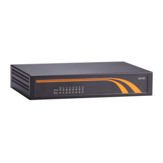
NA345 Series Network Appliance User’s Manual I/O Outlets Locate the front panel I/O outlets on the NA345 Series server to connect serial and Ethernet interface devices. 1.5.1 Front Panel NA345 Power LED It will be lighting when the server is powered on to perform diagnostic tests and check a proper operation. -
Page 13: 1.5.2 Rear Panel
NA345 Series Network Appliance User’s Manual 1.5.2 Rear Panel USB 3.0 DC jack HDMI Reset Power switch Console LAN Ports Reset It is for reset the system to reboot your computer instead of turning off the power switch. It is a better way to reboot your system for a longer life of the system’s power supply. - Page 14 NA345 Series Network Appliance User’s Manual This page is intentionally left blank. Introduction...
-
Page 15: Chapter 2 Hardware Description
NA345 Series Network Appliance User’s Manual CHAPTER 2 HARDWARE DESCRIPTION The NA345 Series are convenient for your various hardware configurations. The chapter 2 will help you get familiar with the hardware. Checklist The package bundled with your NA345 Series should contain the following items... -
Page 16: Board Layout
NA345 Series Network Appliance User’s Manual Board Layout Component Side Hardware Description... -
Page 17: Jumper Settings
NA345 Series Network Appliance User’s Manual Jumper Settings This section provides the information about jumpers and connectors of NA345 Series. Proper jumper settings configure the main board in this appliance to meet your application purpose. We are herewith listing a summary table of all jumpers and default settings for onboard devices, respectively. -
Page 18: Auto Power Button Mode Selection (Jp2)
NA345 Series Network Appliance User’s Manual 2.4.1 Auto Power Button Mode Selection (JP2) Description Function Jumper Setting Auto Power On (Default) Auto Power Button Mode Selection Power on By Power button 2.4.2 RTC Well Rest Selection& Restore BIOS Optimal Defaults... -
Page 19: Lan Bypass Control Jumper (Jp3, Jp4, Jp5)
NA345 Series Network Appliance User’s Manual 2.4.3 LAN Bypass Control Jumper (JP3, JP4, JP5) Use these jumpers to select the LAN Bypass Function. Description Function Jumper Setting LAN Bypass as same as Power Off status LAN Bypass Trigger When LAN Bypass Disable (Default) -
Page 20: Tact Sw1 Selection (Jp11)
NA345 Series Network Appliance User’s Manual 2.4.4 TACT SW1 Selection (JP11) Use this jumper to select the TACT SW1 Function. Description Function Jumper Setting Power On/Off TACT SW1 Lower Button Reset (Default) Function Selection NOTE: If you need GPI sample codes, please contact our FAE directly, and they are for reference purposes only. -
Page 21: Connectors
NA345 Series Network Appliance User’s Manual Connectors Connectors connect the board with other parts of the system. Loose or improper connection might cause problems. Make sure all connectors are properly and firmly connected. Here is a summary table shows you all connectors on the main board. -
Page 22: Hdmi Connector (Cn7)
NA345 Series Network Appliance User’s Manual 2.5.1 HDMI Connector (CN7) Signal Signal HDMI_DATA2+ HDMI_DATA2- HDMI_DATA1+ HDMI_DATA1- HDMI_DATA0+ HDMI_DATA0- HDMI_CLK+ HDMI_CLK- HDMI_SPC HDMI_SPD HDMI_HTPLG 2.5.2 Rear IO USB 3.0 Port (CN8) Signal Signal +VBUS USBD0- USBD0+ SSRX0- SSRX0+ SSTX0- SSTX0+ +VBUS... -
Page 23: Sim Card (Cn1)
NA345 Series Network Appliance User’s Manual 2.5.3 SIM Card (CN1) In order to work properly, the SIM card must be used together with Mini Card (CN4) which is inserted to socket CN1 It is mainly used in 3G wireless network application. -
Page 24: Mini Pcie Full & Half (Cn2, Cn4)
NA345 Series Network Appliance User’s Manual 2.5.4 MINI PCIe Full & Half (CN2, CN4) The CN2 is mini PCIe half, it supports USB2.0 single only and PCIe for optional. The CN4 is mini PCIe full, it supports USB2.0 single only and PCIe for optional, with SIM slot CN1. -
Page 25: Mini Pcie Full (Cn3)
NA345 Series Network Appliance User’s Manual 2.5.5 MINI PCIe Full (CN3) The CN3 supports m-SATA and USB 2.0 interface only. Signal Signal WAKE# +3.3VSB No use No use +1.5V CLKREQ# No use No use REFCLK- No use REFCLK+ No use... -
Page 26: Lcm Connector (Cn5)
NA345 Series Network Appliance User’s Manual 2.5.6 LCM Connector (CN5) Signal NRXD NTXD 2.5.7 SATA Power Connector (CN6) Signal +12V 2.5.8 DC Power Jack (CN10) Signal +12V Ground (GND) Hardware Description... -
Page 27: Internal Usb2.0 Box (Usb1)
NA345 Series Network Appliance User’s Manual 2.5.9 Internal USB2.0 box (USB1) Signal Signal VBUS0 VBUS1 USB6- USB2- USB6+ USB2+ 2.5.10 Fan Connectors (FAN1, FAN2) Signal +12V level Sensor Signal +12V level Sensor Hardware Description... -
Page 28: Vga Connector (Vga1)
NA345 Series Network Appliance User’s Manual 2.5.11 VGA Connector (VGA1) Signal Signal GREEN N.C. BLUE CRT_VCC DDC DATA HSYNC VSYNC DDC CLK N.C. 2.5.12 Front Panel (JP1) Signal Signal PWRLED+ EXT SPEAKER- Buzzer PWRLED- N.C. N.C. EXT SPK+ PWRSW- PWRSW+... -
Page 29: Sata Connector (Sata1, Sata2)
NA345 Series Network Appliance User’s Manual 2.5.13 SATA Connector (SATA1, SATA2) These Serial Advanced Technology Attachment (Serial ATA or SATA) connectors are for high-speed SATA interface ports. SATA2 is co-lay with m-SATA (CN3). Default is m-SATA. Signal 2.5.14 COM2 Port (COM2) -
Page 30: Digital Io (Dio1)
NA345 Series Network Appliance User’s Manual 2.5.16 Digital IO (DIO1) The board is equipped with an 8-channel (4 inputs and 4 outputs) digital I/O connector that meets requirements for a system customary automation control. The digital I/O can be configured to control cash drawers and sense warning signals from an Uninterrupted Power System (UPS), or perform store security control. -
Page 31: Chapter 3 Ami Bios Setup Utility
NA345 Series Network Appliance User’s Manual CHAPTER 3 AMI BIOS SETUP UTILITY This chapter provides users with detailed description how to set up basic system configuration through the AMI Aptio setup utility. Starting To enter the setup screens, follow the steps below: Turn on the computer and press the <Del>... -
Page 32: Main Menu
NA345 Series Network Appliance User’s Manual Main Menu When you first enter the setup utility, you will enter the Main setup screen. You can always return to the Main setup screen by selecting the Main tab. There are two Main Setup options. -
Page 33: Advanced Menu
NA345 Series Network Appliance User’s Manual Advanced Menu The Advanced menu allows users to set the configuration of the CPU and other system devices. You can select any of the items in the left frame of the screen to go to the sub menus: Trusted Computing ►... - Page 34 NA345 Series Network Appliance User’s Manual Trusted Computing This screen provides the function for specifying the TPM settings. Configuration Use this item to enable or disable control TPM function Current State Information Display current TPM status information AMI BIOS Setup Utility...
- Page 35 NA345 Series Network Appliance User’s Manual Super IO Configuration You can use this screen to select options for the Super IO Configuration, and change the value of the selected option. A description of the selected item appears on the right side of the screen.
- Page 36 NA345 Series Network Appliance User’s Manual Serial Port1 Address This option specifies the base I/O port address and Default setting is 3F8. Here are the options for your selection, Disabled. Serial Port2 Address This option specifies the base I/O port address and Default setting is 2F8.
- Page 37 NA345 Series Network Appliance User’s Manual HW Monitor This screen shows the Hardware Health Configuration, and a description of the selected item appears on the right side of the screen System Temperature Show you the current system temperature. CPU Temperature These read-only fields show the functions of the hardware thermal sensor by CPU thermal diode that monitors the chip blocks to ensure a stable system.
- Page 38 NA345 Series Network Appliance User’s Manual Serial Port Console Redirection Terminal Type This item allows you to select the target terminal type. Configuration options: ANSI, VT100 and VT-UTF8. Bits per second This item allows you to setup the data transfer rate for the console port. The default value is 115200.
- Page 39 NA345 Series Network Appliance User’s Manual Stop Bits This item allows you to select the data bits. The configuration options: 1 and 2. Flow Control This item allows you to select flow control for console redirection. The configuration options: None, Hardware and Software.
- Page 40 NA345 Series Network Appliance User’s Manual CPU Configuration This screen shows the CPU Configuration, and you can change the value of the selected option. AMI BIOS Setup Utility...
- Page 41 NA345 Series Network Appliance User’s Manual SATA Configuration You can use this screen to select options for the SATA Configuration, and change the mode of the selected option. AMI BIOS Setup Utility...
- Page 42 NA345 Series Network Appliance User’s Manual LAN Bypass Model Configuration LBP@power on Use LBP @Power On item to configure Power On LAN Bypass to “Disabled” ,“Enabled” or “ Last State” for LAN Bypass . LBP@power off Power off LAN Bypass setting, use LBP @Power Off item to “Disabled” ,“Enabled” or “ Last State”...
-
Page 43: Chipset Menu
NA345 Series Network Appliance User’s Manual Chipset Menu The Chipset menu allows users to change the advanced chipset settings. You can select any of the items in the left frame of the screen to go to the sub menus: North Bridge... -
Page 44: Security Menu
NA345 Series Network Appliance User’s Manual Security Menu The Security menu allows users to change the security settings for the system. Administrator Password This item indicates whether an administrator password has been set (installed or uninstalled). User Password This item indicates whether a user password has been set (installed or uninstalled). -
Page 45: Boot Menu
NA345 Series Network Appliance User’s Manual Boot Menu The Boot menu allows users to change boot options of the system. You can select any of the items in the left frame of the screen to go to the sub menus: For items marked with “... -
Page 46: Save & Exit Menu
NA345 Series Network Appliance User’s Manual Save & Exit Menu The Exit menu allows users to load your system configuration with optimal or failsafe default values. Save Changes and Exit When you have completed the system configuration changes, select this option to leave Setup and reboot the computer so the new system configuration parameters can take effect. -
Page 47: Appendix Alan Bypass Configuration
LAN bypass gives us a solution for this problem. The NA345 series LAN bypass function is very flexible. It can be selected at any time and any stage. You can enable LAN bypass for power on state by jumper, BIOS, or by software program when entering into the OS. -
Page 48: Lan Bypass Register Configuration
Select each segment by setting the corresponding bit to 1. When the bit is set to 0, no action happens upon the segment. NOTE: NA345 series support SEGN1 for LAN3 and Lan4 and SEGN2 for LAN5 and Lan6. Data read back from this register is not defined and therefore must be ignored. Reading from this register makes no effect on LAN bypass function. - Page 49 LAN bypass on the segment when power off. Clearing the bit to 0 disables LAN bypass on the segment when power off. NOTE: NA345 series support SEGF1 for LAN3 and Lan4 and SEGF2 for LAN5 and Lan6. Data read back from this register is not defined and therefore must be ignored. Reading from this register makes no effect on LAN bypass function.
- Page 50 LAN bypass on selected segment(s) based on the setting of Power On Bypass Control register (SEGN1~2). NOTE: NA345 series support SEGN1 for LAN3 and Lan4 and SEGN2 for LAN5 and Lan6. Data (bits 6~0) read back from this register is not defined and therefore must be ignored.
- Page 51 NA345 Series Network Appliance User’s Manual LAN Bypass Status Register (0x8E3) Bit 0 LAN Bypass Seg.1 status Disable=0; Enable=1 Bit 1-3 Not used Bit 7~4 Firmware version Without LAN Bypass function=1111 LAN Bypass Configuration...
- Page 52 NA345 Series Network Appliance User’s Manual This page is intentionally left blank. LAN Bypass Configuration...
-
Page 53: Appendix Bwdt Timer For System Reset
NA345 Series Network Appliance User’s Manual APPENDIX B WDT TIMER FOR SYSTEM RESET WDT (Watchdog Timer) The hardware supports the WDT (Watchdog Timer) function. While time-out happens after a defaulted period, the WDT will reset the system. NOTE: If you need sample codes, please contact our FAE directly, and they are for reference purposes only. - Page 54 NA345 Series Network Appliance User’s Manual This page is intentionally left blank. WDT Timer for System Reset...
-
Page 55: Appendix Cwarning
NA345 Series Network Appliance User’s Manual APPENDIX C WARNING This is a class B Product. In a domestic Environment this Product may cause radio interference in which case the user may be required to take adequate measures. It will be danger if battery is incorrectly replaced. Replacing only with the same or equivalent type is highly recommended by the manufacturer. - Page 56 NA345 Series Network Appliance User’s Manual This page is intentionally left blank. Warning...
Need help?
Do you have a question about the NA345 Series and is the answer not in the manual?
Questions and answers