Table of Contents
Advertisement
Quick Links
Advertisement
Table of Contents

Subscribe to Our Youtube Channel
Related Manuals for AXIOMTEK NA363R


Summary of Contents for AXIOMTEK NA363R
- Page 1 NA363R Network Appliance User’s Manual...
- Page 2 AXIOMTEK does not make any commitment to update the information in this manual. AXIOMTEK reserves the right to change or revise this document and/or product at any time without notice. No part of this document may be reproduced, stored in a retrieval system, or transmitted, in any form or by any means, electronic, mechanical, photocopying, recording, or otherwise, without the prior written permission of AXIOMTEK Co., Ltd.
-
Page 3: Safety Approvals
Safety Approvals CE Marking FCC Class A FCC Compliance This equipment has been tested and complies with the limits for a Class A digital device, pursuant to Part 15 of the FCC Rules. These limits are designed to provide reasonable protection against harmful interference in a residential installation. -
Page 4: Safety Precautions
Most electronic components are sensitive to static electrical charge. 2. Disconnect the power cords from the NA363R Series before making any installation. Be sure both the system and the external devices are turned OFF. Sudden surge of power could ruin sensitive components. -
Page 5: Table Of Contents
1.3.2 Mechanical / Environmental ................3 Dimensions and Outlines ..............4 I/O Outlets ..................5 1.5.1 Front Panel for NA363R ................... 5 1.5.2 Rear Panel for NA363R ..................7 CHAPTER 2 HARDWARE DESCRIPTION ............ 9 Checklist ..................... 9 Memory Module (UDIMM/RDIMM) and HDD ........9 Board Layout .................. - Page 6 Security Menu .................. 58 Boot Menu ..................59 Save & Exit Menu ................63 APPENDIX A LAN BYPASS CONFIGURATION ......... 71 About LAN Bypass ..................71 LAN Bypass Register Configuration .............. 72 APPENDIX B WDT TIMER FOR SYSTEM RESET ........77 APPENDIX C LAN MODULE EXPANSION ..........
-
Page 7: Chapter 1 Introduction
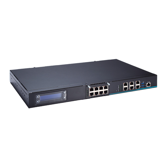
Dimensions and Outlines I/O Outlets General Description The NA363R is a 1U rack mount network security hardware platform for VPN, firewall and ® other network security applications, which consists can support of Intel ATOM C3000 family processors. This platform supports the 1U rack mount form factor, and the system supports DDR4 U-DIMM/R-DIMM memory up to maximum 128 GB. -
Page 8: Specifications
NA363R Series Network Appliance User’s Manual Specifications 1.3.1 System System CPU ® Intel C3000 family processors. (C3558/C3758 in default, other sku for optional) BIOS AMI SPI flash BIOS System Memory Four DDR4 U-DIMM/R-DIMM, non-buffer non-ECC/ECC memory, up to 128GB ... -
Page 9: Mechanical / Environmental
NA363R Series Network Appliance User’s Manual 1.3.2 Mechanical / Environmental Form Factor 1U Rack mount Power, HDD, Link/Act with transfer rate(LAN ports) LAN by pass LED and programmable LED Operation Temperature 0°C ~ 45°C (32°F ~ 113°F) ... -
Page 10: Dimensions And Outlines
NA363R Series Network Appliance User’s Manual Dimensions and Outlines NA363R Introduction... -
Page 11: I/O Outlets
NA363R Series Network Appliance User’s Manual I/O Outlets Locate the front panel I/O outlets on the NA363R Series server to connect serial and Ethernet interface devices. 1.5.1 Front Panel for NA363R USB2.0 Console RJ45 LAN ports NIC module for optional LCM&Keypad... - Page 12 NA363R Series Network Appliance User’s Manual Transfer Rate for LAN port The double-color LED light indicates 10/100/1000Mbps transfer rate. LED Light Color Transfer Rate Dark 10Mbps Green 100Mbps Orange 1000Mbps If the LED is dark and Active/Link LED is lighting on flashing, the transfer rate should be 10Mbps.
-
Page 13: Rear Panel For Na363R
NA363R Series Network Appliance User’s Manual 1.5.2 Rear Panel for NA363R VGA (optional) System Fan System Fan AC Inlet/Switch Power Supply System power use power cord to connect the power supply to AC Inlet with power switch. System Fans(smart fan) These are fans for cooling down system temperature. - Page 14 NA363R Series Network Appliance User’s Manual This page is intentionally left blank. Introduction...
-
Page 15: Chapter 2 Hardware Description
NA363R Series Network Appliance User’s Manual CHAPTER 2 HARDWARE DESCRIPTION The NA363R Series are convenient for your various hardware configurations. The chapter 2 will help you get familiar with the hardware. Checklist The package bundled with your NA363R should contain the following items: The NA363R network appliance hardware platform ... - Page 16 NA363R Series Network Appliance User’s Manual Connects SATA cable and SATA power cable from HDD to SATA connector (SATA1/SATA2) and SATA power connector (CN2/CN3) together then installs HDD by HDD rack and screws properly Hardware Description...
-
Page 17: Board Layout
NA363R Series Network Appliance User’s Manual Board Layout Component Side Hardware Description... - Page 18 NA363R Series Network Appliance User’s Manual Bottom Side Hardware Description...
-
Page 19: Jumper Settings
NA363R Series Network Appliance User’s Manual Jumper Settings This section provides the information about jumpers and connectors of NA363R Series. Proper jumper settings configure the main board in this appliance to meet your application purpose. We are herewith listing a summary table of all jumpers and default settings for onboard devices, respectively. -
Page 20: Lan Bypass Control Selection (Jp7, Jp8, Jp9)
NA363R Series Network Appliance User’s Manual 2.4.2 LAN Bypass Control Selection (JP7, JP8, JP9) Description Function Jumper Setting Mother board/SEGN1 ~2 Bypass as same as Power Off status LAN Bypass Trigger when Power Mother board/SEGN1 ~2 Bypass Disable(Default) Mother board/SEGN1 ~2... -
Page 21: Tact Sw1 Selection (Jp6)
NA363R Series Network Appliance User’s Manual 2.4.3 TACT SW1 Selection (JP6) Use this jumper to select the TACT SW1 Function. Description Function Jumper Setting Power button function Low Button TACT SW 1 Reset button function (Default) Function Selection GPI-2 function NOTE: If you need GPI sample codes please contact our FAE directly, and they are for reference purposes only. -
Page 22: Connectors
NA363R Series Network Appliance User’s Manual Connectors Connectors connect the board with other parts of the system. Loose or improper connection might cause problems. Make sure all connectors are properly and firmly connected. Here is a summary table shows you all connectors on the main board. -
Page 23: Lcm Connector
NA363R Series Network Appliance User’s Manual 2.5.1 LCM Connector Signal LCM1 2.5.2 Digital Input / Output Connector (DIO1) The board is equipped with an 8-channel (4 inputs and 4 outputs, default setting is “High”) digital I/O connector that meets requirements for a system customary automation control. The digital I/O can be configured to control cash drawers and sense warning signals from an Uninterrupted Power System (UPS), or perform store security control. -
Page 24: Serial Port2 Connector (Com2)
NA363R Series Network Appliance User’s Manual 2.5.3 Serial Port2 Connector (COM2) Signal Data Carrier Detect (DCD) Data Set Ready(DSR) Receive Date(RXD) Request to Send(RTS) Transmit Data(TXD) Clear to Send(CTS) Data Terminal Ready(DTR) COM2 Ring Indicator(RI) 2.5.4 FAN Connector (FAN1, FAN2, FAN3) -
Page 25: Sata Power Connector: (Cn2, Cn3)
NA363R Series Network Appliance User’s Manual 2.5.6 SATA Power Connector: (CN2, CN3) The SATA power connector is for providing power to hard disk device. Signal CN2, CN3 +12V 2.5.7 Mini Card Connector (CN5) Default setting is PCIe/USB signal and reserves SATA signal for optional. -
Page 26: Mini Card Connector (Cn6)
NA363R Series Network Appliance User’s Manual 2.5.8 Mini Card Connector (CN6) Default setting is SATA/USB signal and reserves PCIe signal for optional. Signal Signal W AKE_N P3V3_STBY P1V05_S CLK_REQ_N DATA CLK_N CLK_P RESET_N RX_P P3V3_STBY RX_N P1V05_S SMB_CLK TX_N SMB_DATA... -
Page 27: Case Open Connector (Cn7)
NA363R Series Network Appliance User’s Manual 2.5.9 Case Open Connector (CN7) Signal CASEOPEN_N 2.5.10 DC-In Power Jack (CN11) Signal +12V CN11 2.5.11 4P Wafer Power Input Connector (ATX2) Signal +12V +12V ATX2 2.5.12 Power Switch Connector desktop system (ATX1) Signal... -
Page 28: Serial Port For Console (Com1)
NA363R Series Network Appliance User’s Manual 2.5.13 Serial Port for Console (COM1) The COM1 Port connector is a RJ-type connector Signal Request to Send (RTS) Data Terminal Ready (DTR) Transmit Data (TXD) Ground (GND) Ground (GND) Receive Data (RXD) Data Set Ready (DSR) Clear to Send (CTS) 2.5.14 USB port Connector (USB1) -
Page 29: Led1~11
NA363R Series Network Appliance User’s Manual 2.5.15 LED1~11 LED1~11(1~9 for Desktop system, 10~11 for rack mount system) Signal LED1 Up : Power LED (Green) Down : HDD LED (Green) LED2 Up : GPO(Programmable LED) Down : GPO (Programmable LED) LED3... -
Page 30: Front Panel Bezel Connector (Jp1)
NA363R Series Network Appliance User’s Manual 2.5.16 Front Panel Bezel Connector (JP1) Power LED: This 3-pin connector (Pin 1, 3, 5) connects a LED indicator to the system power switch on the case. Pin 1 is assigned as +, and Pin 3, Pin 5 as -. The Power LED lights up when the system is powered ON. -
Page 31: Chapter 3 Ami Bios Setup Utility
NA363R Series Network Appliance User’s Manual CHAPTER 3 AMI BIOS SETUP UTILITY This chapter provides users with detailed description how to set up basic system configuration through the AMIBIOS8 BIOS setup utility. Starting To enter the setup screens, follow the steps below: Turn on the computer and press the <Del>... -
Page 32: Main Menu
NA363R Series Network Appliance User’s Manual Main Menu When you first enter the Setup Utility, you will enter the Main setup screen. You can always return to the Main setup screen by selecting the Main tab. There are two Main Setup options. -
Page 33: Advanced Menu
NA363R Series Network Appliance User’s Manual Advanced Menu The Advanced menu allows users to set configuration of the CPU and other system devices. You can select any of the items in the left frame of the screen to go to the sub menus: ►... - Page 34 NA363R Series Network Appliance User’s Manual Trusted Computing This screen provides the function for specifying the TPM and Security device setting. Security device setup Use this item to enable or disable BIOS support for security device. OS will not show Security Device.
- Page 35 NA363R Series Network Appliance User’s Manual AMI BIOS Setup Utility...
- Page 36 NA363R Series Network Appliance User’s Manual NCT 6102D Super IO Configuration You can use this screen to select options for the Super IO Configuration, and change the value of the selected option. A description of the selected item appears on the right side of the screen.
- Page 37 NA363R Series Network Appliance User’s Manual Serial Port1 Address This option specifies the base I/O port address and Default setting is 3F8h. Here are the options for your selection, Disabled. AMI BIOS Setup Utility...
- Page 38 NA363R Series Network Appliance User’s Manual Serial Port2 Address This option specifies the base I/O port address and Default setting is 2F8h. Here are the options for your selection, Disabled. AMI BIOS Setup Utility...
- Page 39 NA363R Series Network Appliance User’s Manual Chassis Opened Warning Select to enable or disable chassis intrusion detection. Chassis intrusion detection is a utility that can tell whether someone has opened the case and trigger the buzzer on board. Remark: Pin harder design has reserved for customized chassis.
- Page 40 NA363R Series Network Appliance User’s Manual HW Monitor This screen shows the Hardware Health Configuration, and a description of the selected item appears on the right side of the screen. AMI BIOS Setup Utility...
- Page 41 Fan Speed NA363R equips 2pcs fan and it shows cooling fan speed in RPM. If the fan Speed is N/A, it means no fan available. Vcore 5V / 3.3V Show you the voltage of 5V/ 3.3V and etc.
- Page 42 NA363R Series Network Appliance User’s Manual Serial Port Console Redirection To use the external serial port as console, it is needed to enable serial port console redirection. Console Redirection Console Redirection Enable or Disable. AMI BIOS Setup Utility...
- Page 43 NA363R Series Network Appliance User’s Manual Console Redirection Setting This setting specifies how the host computer and the remote computer will exchange data. AMI BIOS Setup Utility...
- Page 44 NA363R Series Network Appliance User’s Manual Terminal Type This item allows you to select the target terminal type. Configuration options: ANSI, VT100, VT100+ and VT-UTF8. AMI BIOS Setup Utility...
- Page 45 NA363R Series Network Appliance User’s Manual Bits per second This item allows you to setup the data transfer rate for the console port. The default value is 115200. Available options are “9600”, “19200”, “38400”, “57600” and “115200”. Data Bits This item allows you to select the data bits. The configuration options: 7 and 8.
- Page 46 NA363R Series Network Appliance User’s Manual Parity This item allows you to select flow control for console redirection. The configuration options: None, Even, Odd, Mark and Space. Stop Bits This item allows you to select the data bits. The configuration options: 1 and 2.
- Page 47 NA363R Series Network Appliance User’s Manual Flow Control This item allows you to select flow control for console redirection. The configuration options: None, Hardware and Software. VT-UTF8 Combo Key Support Use this item to “Enabled” or “Disabled” VT-UTF8 combination key supports for ANSI / VT100 terminals.
- Page 48 NA363R Series Network Appliance User’s Manual Recorder Mode This item allows you to select the recorder mode. The configuration options: Enabled and Disabled. Resolution Enable or disable extended terminal resolution. AMI BIOS Setup Utility...
- Page 49 NA363R Series Network Appliance User’s Manual Putty Keypad This item allows you to select the putty keypad. The configuration options: VT100, LINUX, XTERMR6, SCO, ESCN and VT400. AMI BIOS Setup Utility...
- Page 50 NA363R Series Network Appliance User’s Manual Legacy Console Redirection Settings This item allows you to configure the legacy console redirection. Redirection After BIOS POST Use this item to enable or disable the function of Console Redirection, which allows you maintain a system from a remote location. The default setting is Always.
- Page 51 NA363R Series Network Appliance User’s Manual Remote OS Install This item allows you to select the install legacy OS through remote. The configuration options: “Enabled” or “Disabled”. AMI BIOS Setup Utility...
- Page 52 NA363R Series Network Appliance User’s Manual CSM Configuration (Compatibility Support Module) Use CSM configuration to enable/disable, Option ROM execution setting for LAN by pass function. AMI BIOS Setup Utility...
- Page 53 NA363R Series Network Appliance User’s Manual Lanbypass Mode Configuration LAN bypass Mode @power On Use this item to select lanbypass to “disabled” or “enabled” or keep “Last State.” Lanbypass Mode @power OFF Use this item to select lanbypass to “disabled” or “enabled” or keep “last state.’’...
- Page 54 NA363R Series Network Appliance User’s Manual LAN PXE Boot This item can enable or disable boot option for legacy mass storage devices with option ROM. In LAN PXE Boot control menu and select LAN port from LAN1~LAN6 for PXE ROM Boot to server or Disables it.
- Page 55 NA363R Series Network Appliance User’s Manual Boot option filter This option controls legacy/UEFI ROMs priority. Selects boot option from Boot option filter menu. NOTE: UEFI is Unified Extensible Firmware Interface. It replaces the BIOS firmware interface originally present in legacy BIOS.
- Page 56 NA363R Series Network Appliance User’s Manual Option ROM execution Controls the execution of UEFI and Legacy storage OpROM. NOTE: OpROM: Option ROM, it consists of firmware that is called by system BIOS. OpROM may be from network (PXE ROM or UEFI UNDI driver…etc.), storage (Raid ROM…etc.) or Video (vbios or GOP driver…etc.)
- Page 57 NA363R Series Network Appliance User’s Manual USB Configuration Select this item to set up USB related parameter. Legacy USB support Enables legacy USB support (like USB, KB/MS); Auto option disables legacy support if no USB device are connected; Disable option will keep USB device available only for EFI applications.
-
Page 58: Intelrcsetup
NA363R Series Network Appliance User’s Manual IntelRCSetup Processor Configuration Displays processor information and provides option to change the processor setting. Enable or disable EIST (GV3). TM1 must be enabled for TM2 to be available. GV3 must be enabled for Turbo. - Page 59 NA363R Series Network Appliance User’s Manual Server ME Configuration Configure Server ME Technology parameters. Here show the general ME configuration information. NOTE: ME, Management Engine. It is Intel’s technology used for remote out-of-band management. AMI BIOS Setup Utility...
- Page 60 NA363R Series Network Appliance User’s Manual North Bridge Chipset Configuration North Bridge handles high speed interface. For example: RAM and PCIe. Show or configure related information/parameters in this item. SSA Configuration Enable or disable VT-d function. NOTE: VT-d, stands for "Intel Virtualization Technology for Directed I/O. VT-d is for isolating and restricting device accesses to the owner of the partition managing the device.
- Page 61 NA363R Series Network Appliance User’s Manual South Bridge Chipset Configuration South Bridge handles slow speed I/O interface. Configure related parameters in this item. AMI BIOS Setup Utility...
- Page 62 NA363R Series Network Appliance User’s Manual SATA Configuration There are options for South Bridge SATA configuration. Enable SATA Controller Enable or disable SATA controller if supported by current CPU SKU. There are SATA and mSATA devices list. Select one to show information of SATA device. Enable or disable SATA device.
- Page 63 NA363R Series Network Appliance User’s Manual AMI BIOS Setup Utility...
-
Page 64: Security Menu
NA363R Series Network Appliance User’s Manual Security Menu The Security menu allows users to change the security settings for the system. Administrator Password This item indicates whether an administrator password has been set (installed or uninstalled). AMI BIOS Setup Utility... -
Page 65: Boot Menu
NA363R Series Network Appliance User’s Manual Boot Menu The Boot menu allows users to change boot options of the system. You can select any of the items in the left frame of the screen to go to the sub menus: For items marked with “”, please press <Enter>... - Page 66 NA363R Series Network Appliance User’s Manual Boot Num-Lock Use this item to select the power-on state for the NumLock. The default setting is on. Quiet Boot Enable or disable quiet boot option. AMI BIOS Setup Utility...
- Page 67 NA363R Series Network Appliance User’s Manual Boot Option Priorities Boot Option #1 / Boot Option #1 Setup the system boot order. AMI BIOS Setup Utility...
- Page 68 NA363R Series Network Appliance User’s Manual Hard Drive BBS Priority Setup the order of the legacy devices here. AMI BIOS Setup Utility...
-
Page 69: Save & Exit Menu
NA363R Series Network Appliance User’s Manual Save & Exit Menu The Exit menu allows users to load your system configuration with optimal or failsafe default values. Save Options Save Changes and Exit When you have completed the system configuration changes, select this option to leave Setup and reboot the computer so the new system configuration parameters can take effect. - Page 70 NA363R Series Network Appliance User’s Manual Discard Changes and Exit Select this option to quit Setup without making any permanent changes to the system configuration. Select Discard Changes and Exit from the Exit menu and press <Enter>. Select Ok to discard changes and exit.
- Page 71 NA363R Series Network Appliance User’s Manual Save Changes and Reset Reset the system after saving the changes. Discard Changes and Reset Reset system setup without saving any changes. AMI BIOS Setup Utility...
- Page 72 NA363R Series Network Appliance User’s Manual Save Changes Save Change done so far to any of the setup options. Discard Changes Use this item to abandon all changes. AMI BIOS Setup Utility...
- Page 73 NA363R Series Network Appliance User’s Manual Default Options Restore Defaults Restore/Load default value for all the setup options. Save as User Defaults Save the changes done so far as User Defaults. AMI BIOS Setup Utility...
- Page 74 NA363R Series Network Appliance User’s Manual Restore User Default Restore the User Default to all the setup options. NOTE: There are 2 kind of BIOS default setting: factory default and optimized default. AMI BIOS Setup Utility...
- Page 75 NA363R Series Network Appliance User’s Manual Boot Override Launch EFI Shell from filesystem device Attempts to launch EFI shell application (Shellx64.efi) from one of the available filesystem device. AMI BIOS Setup Utility...
- Page 76 NA363R Series Network Appliance User’s Manual This page is intentionally left blank. AMI BIOS Setup Utility...
-
Page 77: Appendix Alan Bypass Configuration
LAN bypass gives us a solution for this problem. The NA363R series LAN bypass function is very flexible. It can be selected at any time and any stage. You can enable LAN bypass for power on state by jumper, BIOS, or by software program when entering into the OS. -
Page 78: Lan Bypass Register Configuration
NA363R Series Network Appliance User’s Manual LAN Bypass Register Configuration AX98614 Coverter Board Mother Board Slot 2 (SBC8A363) Lan Module Slot 1 Power ON Bypass Control Register Address: Mother board/Slot1 LAN module/Slot2 0x8E0 0x8E4 BYM1 BYM0 SEGN4 SEGN3 SEGN2 SEGN1... - Page 79 NA363R Series Network Appliance User’s Manual The relay closes immediately to form LAN bypass on selected segment when power on. Force bypass disable LAN bypass is disabled immediately on selected segment when power on. Timer enable When power on, the selected segments are controlled by the setting of LAN bypass Timer Control register.
- Page 80 NA363R Series Network Appliance User’s Manual Power OFF Bypass Control Register Address: Mother board/Slot1 LAN module/Slot2 0x8E1 0x8E5 SEGF4 SEGF3 SEGF2 SEGF1 Default value: 00000000 Bit 4~7 Not used. Bit 0~3 SEGF1~4 Use the corresponding bit to configure each segment. Setting the bit to 1 enables LAN bypass on the segment when power off.
- Page 81 NA363R Series Network Appliance User’s Manual LAN Bypass Timer Control Register Address: Mother board/Slot1 LAN module/Slot2 0x8E2 0x8E6 TEXP TVAL2 TVAL1 TVAL0 Default value: 00000000 Bit 7 TEXP (Read Only) This bit indicates the status of hardware timer. Timer has not expired Timer has expired Bits 6~3 Not used.
- Page 82 NA363R Series Network Appliance User’s Manual LAN Bypass Status Register Address: Mother board/Slot1 LAN module/Slot2 0x8E3 0x8E7 VER3 VER2 VER1 VER0 LAN Bypass Seg.1 status Disable=0; Enable=1 Bit 0 Bit 1-3 Not used Bit 7~4 Firmware version Without LAN Bypass function=1111...
-
Page 83: Appendix Bwdt Timer For System Reset
NA363R Series Network Appliance User’s Manual APPENDIX B WDT TIMER FOR SYSTEM RESET WDT (Watchdog Timer) The hardware supports the WDT (Watchdog Timer) function. While time-out happens after a defaulted period, the WDT will reset the system. NOTE: If you need sample codes please contact our FAE directly, and they are for reference purposes only. - Page 84 NA363R Series Network Appliance User’s Manual This page is intentionally left blank. WDT Timer for System Reset...
-
Page 85: Appendix C Lan Module Expansion
NA363R Series Network Appliance User’s Manual APPENDIX C LAN MODULE EXPANSION You can install LAN module(s) into NA363R front-accessible expansion slots to meet your application requirement. Here are some LAN module configurations for your selection: LAN Modules Slim Module... -
Page 86: Lan Bypass Control Jumper (Jp2/Jp3)
NA363R Series Network Appliance User’s Manual LAN Bypass Control Jumper (JP2/JP3) Use this jumper to select the LAN Bypass Function. Description Function Jumper Setting All SEG. Bypass as same as Power Off status LAN Bypass Trigger when All SEG Bypass Disable(Default) - Page 87 NA363R Series Network Appliance User’s Manual LED Definition AX93316 LAN bypass LED LAN bypass LED W hile running the LAN By-Pass function, the LED always lights up. Active LED (Single color)for LAN port #1, port#2, port#3, port#4, port #5, port#6, port#7, port#8 ...
- Page 88 NA363R Series Network Appliance User’s Manual AX93336-4GIL LAN bypass LED LAN bypass LED W hile running the LAN By-Pass function, the LED always lights up. Active LED (Single color)for LAN port #1, port#2, port#3, port#4 The orange LED is on when the LAN port connection is working.
- Page 89 NA363R Series Network Appliance User’s Manual AX93336-4FI Transfer Rate LED Light Color Fiber port Active: Orange Fiber port Link: Orange LAN Module Expansion...
- Page 90 NA363R Series Network Appliance User’s Manual AX93322-8FI Transfer Rate LED Light Color Down Fiber port Active: Orange Up Fiber port Active: Orange Down Fiber port Link: Orange Up Fiber port Link: Orange LAN Module Expansion...
- Page 91 NA363R Series Network Appliance User’s Manual AX93322-8MIL LAN bypass LED FIBER: Transfer Rate LED Light Color Down Fiber port Active: Orange Up Fiber port Active: Orange Down Fiber port Link: Orange Up Fiber port Link: Orange Copper: LAN bypass LED W hile running the LAN By-Pass function, the LED always lights up.
- Page 92 NA363R Series Network Appliance User’s Manual Link LED for LAN port #1, port#2, port#3, port#4 The double-color LED light indicates 10/100/1000Mbps transfer rate. W hen the orange-color LED light is radiating, it should be 1000Mbps transfer rate.
- Page 93 NA363R Series Network Appliance User’s Manual W hen this LED and Link/Active LED both are dark. No networking devices are attached Transfer Rate LED Light Color 1000Mbps Green 10000Mbps Orange AX93307 LAN bypass LED LAN bypass LED W hile running the LAN By-Pass function, the LED always lights up.
- Page 94 NA363R Series Network Appliance User’s Manual This page is intentionally left blank. LAN Module Expansion...
-
Page 95: Appendix Dwarning
NA363R Series Network Appliance User’s Manual APPENDIX D WARNING This is a class A Product. In a domestic Environment this Product may cause radio interference in which case the user may be required to take adequate measures. It will be danger if battery is incorrectly replaced. Replacing only with the same or equivalent type is highly recommended by the manufacturer. - Page 96 NA363R Series Network Appliance User’s Manual This page is intentionally left blank. Warning...
Need help?
Do you have a question about the NA363R and is the answer not in the manual?
Questions and answers