Table of Contents
Advertisement
Quick Links
Advertisement
Table of Contents

Subscribe to Our Youtube Channel
Related Manuals for AXIOMTEK Apollo Lake NA347 Series


Summary of Contents for AXIOMTEK Apollo Lake NA347 Series
- Page 1 NA347 Series Network Appliance User’s Manual...
- Page 2 Axiomtek does not make any commitment to update the information in this manual. Axiomtek reserves the right to change or revise this document and/or product at any time without notice. No part of this document may be reproduced, stored in a retrieval system, or transmitted, in any form or by any means, electronic, mechanical, photocopying, recording, or otherwise, without the prior written permission of Axiomtek Co., Ltd.
- Page 3 Safety Approvals CE Marking FCC Class B FCC Compliance This equipment has been tested and complies with the limits for a Class B digital device, pursuant to Part 15 of the FCC Rules. These limits are designed to provide reasonable protection against harmful interference in a residential installation.
- Page 4 When handling boards and components, wear a wrist-grounding strap, available from most electronic component stores. Trademarks Acknowledgments Axiomtek is a trademark of Axiomtek Co., Ltd. ® Windows is a trademark of Microsoft Corporation. IBM, PC/AT, PS/2, VGA are trademarks of International Business Machines Corporation.
-
Page 5: Table Of Contents
Table of Contents Section 1 Introduction ............1 1.1 General Description ....................1 1.2 Features ........................... 1 1.3 Specifications ........................ 2 1.3.1 Block Diagram ....................2 1.3.2 Specifications ....................3 1.4 Dimensions and Outlines ..................4 1.5 I/O Outlets ........................5 Section 2 Hardware and Installation ........ - Page 6 3.8 Save & Exit Menu ....................... 42 Appendix A LAN Bypass Configuration ......... 49 About LAN Bypass ......................49 Appendix B WDT Timer for System Reset ......51 WDT (Watchdog Timer) ....................51 Appendix C Warning ............... 53...
-
Page 7: Introduction
NA347 User’s Manual Section 1 Introduction This chapter contains general information and detailed specifications of the NA347 Series Network Appliance Server. It contains the following sections: General Description Features Specifications Dimensions and Outlines I/O Outlets General Description The NA347 is a compact desktop network security hardware platform for VPN, firewall and other network security applications, which can support Intel®... -
Page 8: Specifications
NA347 User’s Manual Specifications 1.3.1 Block Diagram Introduction... -
Page 9: 1.3.2 Specifications
NA347 User’s Manual 1.3.2 Specifications Model NA347 SBCs SBC8A347 Form Factor Desktop Chassis Material Steel Chipset Processor/Cache Intel® Celeron® N3350 1.1GHz/2C/2M/6W BIOS AMI 128Mbits PnP Flash BIOS with function of BIOS redirected to COM port System Memory 1 x DDR3L SO-DIMM socket, up to 8GB none-buffer non-ECC / ECC, up to1866MHz Super I/O Controller: NCT6102D LQFP128 NUVOTON... -
Page 10: Dimensions And Outlines
NA347 User’s Manual Dimensions and Outlines The following diagram shows you dimensions and outlines of the NA347 Series. Unit: mm Introduction... -
Page 11: I/O Outlets
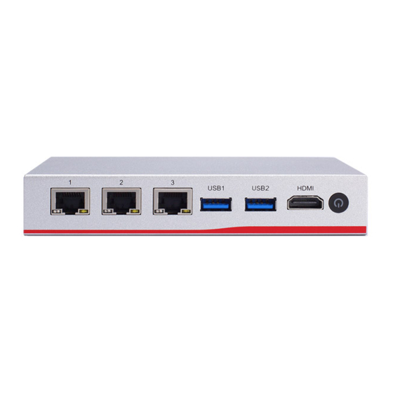
NA347 User’s Manual I/O Outlets Locate front and rear panel I/O outlets on the NA347 Series server to connect serial and Ethernet interface devices. LAN ports USB 3.0 HDMI Power Button Console DC Jack NOTE: Please visit Axiometk Support Page and enter the product category to download the sample code package. - Page 12 NA347 User’s Manual Active LED (Single color) for LAN port #1, port#2, port#3, port#4 1. The orange LED is on when the LAN port connection is working. 2. The LED flashes when transmitting or receiving any signals to or from the appliance. 3.
-
Page 13: Hardware And Installation
4 x Plastic stand for stack-up If you cannot find this package or any items are missing, please contact Axiomtek distributors immediately. If you order any optional components, the package might contain those additional hardware or documents accordingly. -
Page 14: Installation Of Memory Module (So-Dimm)
NA347 User’s Manual Installation of Memory Module (SO-DIMM) The main board supports one DDR3L-1866 SO-DIMM slot with maximum of up to 8GB non-ECC memory. The following steps show you how to install the memory modules: Step.1 Turn off the system and unplug the power cord. Step.2 Loosen four screws to remove bottom cover. -
Page 15: Installation Of Mini-Pcie Module
NA347 User’s Manual Installation of Mini-PCie Module Step.1 Turn off the system and unplug the power cord. Step.2 Loosen four screws to remove bottom cover. Step.3 Identify the full-size mini PCIe slots, insert a mini PCIe module into the sockets and then fasten all screws. Hardware and Installation... -
Page 16: Installation Of M.2 2242 Module
NA347 User’s Manual Installation of M.2 2242 Module Step.1 Turn off the system and unplug the power cord. Step.2 Loosen four screws to remove bottom cover. Step.3 Identify the M.2 2242 slots, insert a M.2 SSD module into the sockets and then fasten all screws. -
Page 17: Board Layout
NA347 User’s Manual Board Layout COM1 SDIMM1 LAN2 LAN3 LAN1 Hardware and Installation... - Page 18 NA347 User’s Manual BOTTOM Hardware and Installation...
-
Page 19: Rtc/Cmos Clear Switch (Sw2)
NA347 User’s Manual RTC/CMOS Clear Switch (SW2) Use this switch to erase and restore CMOS memory and BIOS setting. Put the button for a few seconds then doing this procedure CMOS data resets to its safe default settings. Description Function Switch Setting Normal (Default) RTC/COMS Clear... -
Page 20: Connectors
NA347 User’s Manual Connectors Signals go to other parts of the system through connectors. Loose or improper connection might cause problems, please make sure all connectors are properly and firmly connected. Here is a summary table which shows all connectors on the hardware. Connectors Label DC Jack for 12VDC Power Input... -
Page 21: Mini Pcie Full Connector (Cn2)
NA347 User’s Manual 2.7.1 Mini PCIe full connector (CN2) The CN2 is mini PCIe full, it supports PCIE/USB2.0 single, with NANO SIM slot CN4 Signal Signal PCIE_WAKE0_N +3.3VSB No use Ground (GND) No use +1.5V No use SIM_PWR Ground (GND) SIM_DATA PCIE_CLK- SIM_CLK... -
Page 22: Lan Port (Lan1~Lan3)
NA347 User’s Manual 2.7.2 LAN Port (LAN1~LAN3) Signal Signal MDI0+ MDI2+ MDI0- MDI2- MDI1+ MDI3+ MDI1- MDI3- LED1 100 LAN LED (Green)/ 1000 LAN LED (Orange) LED2 Active LED (Yellow) 2.7.3 USB3.0 Port0 ~ Port1 Connector (CN6~CN7) Signal Signal USB_POWER USBN USBP Ground (GND) -
Page 23: Hdmi (Cn8)
NA347 User’s Manual 2.7.5 HDMI (CN8) Signal Signal HDMI_DATA2+ HDMI_DATA2- HDMI_DATA1+ HDMI_DATA1- HDMI_DATA0+ HDMI_DATA0- HDMI_CLK+ HDMI_CLK - HDMI_SCL HDMI_SDA HDMI_HTPLG 2.7.6 Serial Port1 (For Console) (COM1) Signal Signal RTS1 DTR1 TXD1 RXD1 DSR1 CTS1 Hardware and Installation... - Page 24 NA347 User’s Manual This page is intentionally left blank. Hardware and Installation...
-
Page 25: Ami Bios Setup Utility
NA347 User’s Manual Section 3 AMI BIOS Setup Utility The AMI BIOS provides users with a built-in setup program to modify basic system configuration. All configured parameters are stored in a battery-backed-up RAM (CMOS RAM) to save the setup information whenever the power is turned off. This chapter provides users with detailed description about how to set up basic system configuration through the AMI BIOS setup utility. -
Page 26: Main Menu
NA347 User’s Manual Main Menu When you first enter the setup utility, you will enter the Main setup screen. You can always return to the Main setup screen by selecting the Main tab. There are two Main Setup options. They are described in this section. The Main BIOS Setup screen is shown below. System Language ... - Page 27 NA347 User’s Manual System Date/Time Use this option to change the system time and date. Highlight System Time or System Date using the <Arrow> keys. Enter new values through the keyboard. Press the <Tab> key or the <Arrow> keys to move between fields. The date must be entered in MM/DD/YY format. The time is entered in HH:MM:SS format.
-
Page 28: Advanced Menu
NA347 User’s Manual Advanced Menu The Advanced menu also allows users to set configuration of the CPU and other system devices. You can select any of the items in the left frame of the screen to go to the sub menus: NCT6102D Super IO Configuration ... - Page 29 NA347 User’s Manual NCT6102D Super IO Configuration You can use this screen to select options for the Super IO Configuration, and change the value of the selected option. A description of the selected item appears on the right side of the screen.
- Page 30 NA347 User’s Manual Serial Port 1 Configuration This option specifies the base I/O port address and Interrupt Request address of serial port 1. The Optimal setting is 240h/IRQ4. AMI BIOS Setup Utility...
- Page 31 NA347 User’s Manual NCT6102D HW Monitor This screen monitors hardware health status. AMI BIOS Setup Utility...
- Page 32 NA347 User’s Manual Serial Port Console Redirection AMI BIOS Setup Utility...
- Page 33 NA347 User’s Manual AMI BIOS Setup Utility...
- Page 34 NA347 User’s Manual Console Redirection Settings Terminal Type This item allows you to select the target terminal type. Configuration options: ANSI, VT100 and VT-UTF8. Bits per second This item allows you to setup the data transfer rate for the console port. The default value is 115200.
- Page 35 NA347 User’s Manual Putty KeyPad This item allows you to select the putty keypad. The configuration options: VT100, LINUX, XTERMR6, SCO, ESCN and VT400. Install Legacy OS through Remote This item allows you to select the install legacy OS through remote. The configuration options: “Enabled”...
- Page 36 NA347 User’s Manual CPU Configuration This screen shows the CPU Configuration, and you can change the value of the selected option. Choose Socket 0 CPU Information AMI BIOS Setup Utility...
- Page 37 NA347 User’s Manual Socket 0 CPU Information Monitor Mwait AMI BIOS Setup Utility...
- Page 38 NA347 User’s Manual CSM Configuration This screen shows the CSM Configuration, and you can enable/disable option ROM execution settings. AMI BIOS Setup Utility...
- Page 39 NA347 User’s Manual Network AMI BIOS Setup Utility...
- Page 40 NA347 User’s Manual USB Configuration Use this item for further setting USB port configuration. USB Mass Storage Driver Support AMI BIOS Setup Utility...
-
Page 41: Chipset Menu
NA347 User’s Manual Chipset Menu The Chipset menu allows users to change the advanced chipset settings. You can select any of the items in the left frame of the screen to go to the sub menus: North Bridge South Cluster Configuration ... - Page 42 NA347 User’s Manual South Cluster Configuration AMI BIOS Setup Utility...
-
Page 43: Security Menu
NA347 User’s Manual Security Menu The Security menu allows users to change the security settings for the system. Administrator Password This item indicates whether an administrator password has been set (installed or uninstalled). AMI BIOS Setup Utility... -
Page 44: Boot Menu
NA347 User’s Manual Boot Menu The Boot menu allows users to change boot options of the system. You can select any of the items in the left frame of the screen to go to the sub menus: Boot Configuration Boot Option Priorities ... - Page 45 NA347 User’s Manual Boot Option Priorities You could set the system boot order of the legacy devices in this group. You could set the system boot order in Boot Option. Boot Option #1 Boot Option #2 AMI BIOS Setup Utility...
- Page 46 NA347 User’s Manual Boot Option #3 Boot Option #4 AMI BIOS Setup Utility...
- Page 47 NA347 User’s Manual Boot Option Priorities AMI BIOS Setup Utility...
-
Page 48: Save & Exit Menu
NA347 User’s Manual Save & Exit Menu The Save & Exit menu allows users to load your system configuration with optimal or fail-safe default values. Save Options Default Options Save Options Save Changes and Exit When you have completed the system configuration changes, select this option to leave Setup and return to Main Menu. - Page 49 NA347 User’s Manual Discard Changes and Exit Select this option to quit Setup without making any permanent changes to the system configuration and return to Main Menu. Select Discard Changes and Exit from the Save & Exit menu and press <Enter>. Select Yes to discard changes and exit. Save Changes and Reset When you have completed the system configuration changes, select this option to save changes.
- Page 50 NA347 User’s Manual Discard Changes and Reset Select this option to quit Setup without making any permanent changes to the system configuration. Select Discard Changes from the Save & Exit menu and press <Enter>. Select <Yes> to discard changes and reset system. Save Changes When you have completed the system configuration changes, select this option to save changes.
- Page 51 NA347 User’s Manual Discard Changes Select this option to quit Setup without making any permanent changes to the system configuration. Select Discard Changes from the Save & Exit menu and press <Enter>. Select <Yes> to discard changes and reset system. AMI BIOS Setup Utility...
- Page 52 NA347 User’s Manual Default Options Restore Defaults It automatically sets all Setup options to a complete set of default settings when you select this option. The Optimal settings are designed for maximum system performance, but may not work best for all computer applications. In particular, do not use the Optimal Setup options if your computer is experiencing system configuration problems.
- Page 53 NA347 User’s Manual Restore User Defaults It automatically sets all Setup options to a complete set of User Defaults when you select this option. Select Restore User Defaults from the Save & Exit menu and press <Enter>. AMI BIOS Setup Utility...
- Page 54 NA347 User’s Manual UEFI : Built-in EFI Shell AMI BIOS Setup Utility...
-
Page 55: Appendix Alan Bypass Configuration
NA347 User’s Manual Appendix A LAN Bypass Configuration About LAN Bypass What is the LAN by-pass meant for NA347 Series It doesn’t have any down time in network connections for two other network segments (LAN1 and LAN2) when any fetal errors occur to this device. - Page 56 NA347 User’s Manual This page is intentionally left blank. LAN Bypass Configuration...
-
Page 57: Appendix Bwdt Timer For System Reset
NA347 User’s Manual Appendix B WDT Timer for System Reset WDT (Watchdog Timer) The hardware supports the WDT (Watchdog Timer) function. While time-out happens after a defaulted period, the WDT will reset the system. Note: Please refer to BIOS “WDT function selection”. Note: Please visit Axiometk Support Page and enter the product category to download the... - Page 58 NA347 User’s Manual This page is intentionally left blank. WDT Timer for System Reset...
-
Page 59: Appendix C Warning
NA347 User’s Manual Appendix C Warning This is a class A Product. In a domestic Environment this Product may cause radio interference in which case the user may be required to take adequate measures. It will be danger if battery is incorrectly replaced. Replacing only with the same or ...
Need help?
Do you have a question about the Apollo Lake NA347 Series and is the answer not in the manual?
Questions and answers