Table of Contents
Advertisement
Quick Links
Advertisement
Table of Contents

Related Manuals for Sony UP-D70


Summary of Contents for Sony UP-D70
- Page 1 DIGITAL COLOR PRINTER UP-D70/D70A SERVICE MANUAL Vol. 1 (1st Edition)
- Page 2 MANUAL STRUCTURE Purpose of this manual This manual is the Service Manual Vol.1 of the digital color printer UP-D70/D70A. This manual contains the operating instructions, service information, mechanical operation, circuit operation description, service mode and trouble shooting. Related manuals In addition to this Service Manual Vol.1, the following manual is provided.
- Page 3 5-1. SERVICE MODE ................... 5-1 5-2. ADJUST MODE .................... 5-9 5-3. FMY PRINTING (For UP-D70A only) ............5-11 5-4. PRINT CONFIRMATION OF UP-D70 ............5-11 5-5. RESET OF EACH KIND SETTING VALUE ..........5-12 5-6. NOTE ON THE UNIT TRANSPORTATION ..........5-13 6.
- Page 5 3-864-122-11 (1) Digital Color Printer Operating Instructions Page 2 UP-D70 UP-D70A © 1998 by Sony Corporation...
-
Page 6: Table Of Contents
Record these number in the space provided below. System Overview .............. 5 Refer to these numbers whenever you call upon your Sony dealer regarding this product. System Configuration............5 Location and Function of Parts and Controls ....6 Model No. -
Page 7: About This Manual
Introduction System Overview About this Manual The Sony UP-D70/D70A digital color printer is designed to reproduce computer This manual covers the following UP-D70 series digital color printers. images on A4-size and Letter-size print paper. • UP-D70 You can print out image data of MS-Windows or Macintosh graphics application •... -
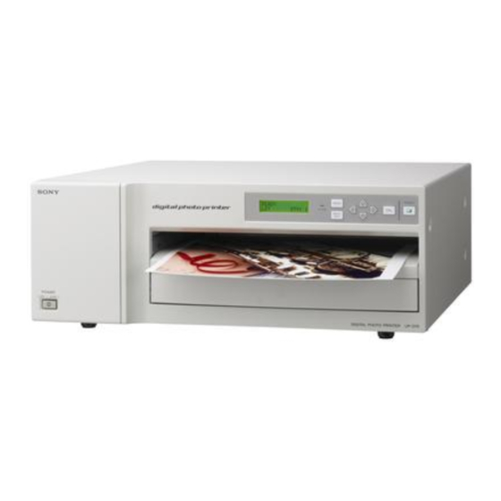
Page 8: Location And Function Of Parts And Controls
Location and Function of Parts and Controls For details, refer to the pages indicated in parentheses. Rear Front UP-D70A UP-D70 5 Expansion slot for Color Connectivity 1 PARALLE DATA IN (Amphenol 36- 1 UPOWER switch 7 MENU button (13, 23, 25) -
Page 9: Supplied Accessories
Preparation Supplied Accessories Assembly This printer is packed together with the following accessories. Check that nothing is missing from your package. Mount the supplied ink ribbon holder, paper tray, paper cover, bottom cover and fan cover. Paper tray (1) Paper cover (1) Note You cannot mount the ink ribbon holder when the thermal head is locked. -
Page 10: Connections
This section introduces the connections of the UP-D70A. For the connection of the When connecting a printer via the SCSI interface UP-D70, see the instruction manual supplied with the TMax P891 Color Connectivity Controller. For details, contact your Sony dealer. -
Page 11: Connecting The Ac Power Cord
If the setting is incorrect, set to the SCSI DEVICE TYPE to 3 using the ı or ∫ button. Instruction in this section is common to UP-D70 and UP-D70A. Turn off the printer. Connect the supplied AC power cord to the AC IN connector on the rear of the The SCSI DEVICE TYPE is set to 3. -
Page 12: Before Printing
Operation Before Printing Remove the ink ribbon cassette by pressing the EJECT button. This section describes the operations that must be performed prior to starting The ink ribbon cassette pops out. printing. This explanation assumes that the printer has already been installed and that all connections have been made. -
Page 13: Loading The Print Paper
Load the print paper by the following procedure. Be careful not to touch the printing surface of the paper. SONY mark faces forwards. Note When loading the print paper, do not turn off the power. If you turn off the power, the image data stored in the memory will be lost. -
Page 14: Printing
PRINT button of the printer. For details on UP-D70A, also see the ReadMe file on the supplied CD-ROM. When your printer is UP-D70, also see the instruction manual of the printer driver software you are using. - Page 15 http://getMANUAL.com Printing (Continued) 2The stored image data is printed as soon as the print command is entered If the printer does not print from the computer or the PRINT button of the printer is pressed. The printer will fail to print in the following cases: •...
-
Page 16: Setting The Print Quantity
Setting the Print Quantity Adjusting the Printouts You can set a print quantity value up to 20 before or during printing. You can adjust the picture quality of a printout with the MENU button before printing. The most recent setting remains effective until changed. 1, 3 1, 4 2, 3 Press the PRINT QTY button. -
Page 17: Adjusting The Gray Balance
Adjusting the Printouts (Contineud) Adjusting the Gray Balance Adjustment items The ink ribbon and the paper are contained in one same package as a pair. The gray Adjustment content balance may differ depending on each pair. It is recommended that you adjust the Color Red becomes stronger. -
Page 18: Precautions
Others Adjusting the Gray Balance (Continued) Precautions Display the pattern No. selected in step 2 or step 4 by pressing the ı or ∫ Safety button. Example: When you decided that the printout of the No.18 gray pattern was the •... -
Page 19: On Transportation
Precautions (Continued) Clean the fan using the vacuum cleaner and the like. On Transportation Notes Do not transport the printer with the supplied accessories. Doing so may cause • Be careful that the filter will be caught in the cleaner. malfunction. -
Page 20: Ink Ribbon And Print Paper
Ink Ribbon and Print Paper Specifications You need print paper and ink ribbon cassette for printing. (“Ink ribbon cassette” Power requirements Accessories supplied stands for the supplied ink ribbon holder loaded with ink ribbon.) Use the ink 120 V AC, 50/60Hz Ink ribbon holder (1) ribbon and print paper contained in the same package. -
Page 21: Troubleshooting
CHECK PAPER AND The print paper may be jammed. PRESS [∫] the printer and consult with your Sony dealer. n Remove jammed paper from the printer, if there is any. Ensure that no paper jammed, then press ∫ button. (page... -
Page 22: If The Paper Jams
Troubleshooting (Continued) Remove the bottom cover. If the Paper Jams If the paper jams, printing stops and the error message stating “CHECK PAPER AND PRESS [∫]” or “REMOVE PAPER AND PRESS [∫]” appears on the printer window display. Follow the steps below to remove the jammed paper. Remove the paper cover. -
Page 23: Index
Index RED 24 AC IN connector 12 GAMMA 24 Paper cover 9 AC power cord 8, 12 Gray balance 25 Paper jams 34 Ribbon and print paper 30 Ribbon door 14 Accessories supplied 8, 31 GREEN 24 Paper outlet 20 Adjusting the gray balance 25 Paper tray 9, 17, 18 Adjusting the printouts 23... - Page 25 Remove axes of head guide (M) assembly from head driving arm (F) (R). Screw (BVTT 3 x 6) 32 core flat type wire Two screws (PSW 3 x 14) Remove the thermal head. Turn the head assembly over. UP-D70/D70A (UC,CE)
- Page 26 Density of paper of item (3) should be checked, if necessary, thermal head voltage fine adjustment should be performed. 3. When Replacing Bar Code, Ribbon Code and OHP Sensors After entering ADJUST mode, luminance quantity adjustment for replaced sensor should be performed. UP-D70/D70A (UC,CE)
- Page 27 2-2. LOCATION OF MAIN PARTS Switching regulator SE-503 IF-610 (UP-D70A) Thermal head MEM-96 (UP-D70A) FMY-15 (UP-D70A) SE-507 SY-270 SE-497 SE-504 SE-498 SE-506 SU-51 SU-50 SU-48 SE-505 MEC-11 SE-502 SU-49 Liquid crystal indication panel unit UP-D70/D70A (UC,CE)
- Page 28 2. Removal of the Front Panel Assembly Top cover Four screws (M3) fixing case Two screws (BVTT 3 x 6) Open the ribbon door. Connector Two screws (CN6-22 pin) (BVTT 3 x 20) Front panel assembly Two screws (BVTT 3 x 6) UP-D70/D70A (UC,CE)
- Page 29 Three screws (BVTT 3 x 6) 4. Removal of the Rear Panel Rear panel Four screws (BVTT 3 x 6) Two screws (BVTT 3 x 6) Blind plate PS blind plate Eight screws (BVTT 3 x 6) UP-D70/D70A (UC,CE)
- Page 30 Hooks Power load Screw (BVTT 3 x 6) 6. Removal of the Partition Assembly Screw (BVTT 3 x 6) Remove the partition assembly from two hooks as indicated by arrow A. Hooks Two screws (BVTT 3 x 6) UP-D70/D70A (UC,CE)
- Page 31 Seven screws (BVTT 3 x 6) Four screws (BVTT 3 x 6) Two screws (BVTT 3 x 6) MEC-11 board Connector (Thermal head) Top plate Corner (T) CN406 15P CN403 6P CN404 8P CN408 3P CN409 3P CN405 11P CN407 5P Seven connectors UP-D70/D70A (UC,CE)
- Page 32 10. Removal of the DC Motor Assembly (Motor Bracket (K) Assembly) Motor bracket (K) assembly DC motor assembly Worm assembly Screw (BVTT 3 x 6) Two screws Worm shaft (BVTT 3 x 5) Two screws (BVTT 3 x 6) UP-D70/D70A (UC,CE)
- Page 33 Three screws (BVTT 3 x 6) 12. Removal of the Head Drive Shaft Assembly Capstan drive cam, parallel pin,bearing (L) Head drive shaft assembly Tension coil spring Screw (BVTT 3 x 6), code drive assembly Lock washer, worm wheel Bearing (L) UP-D70/D70A (UC,CE)
- Page 34 13. Removal of IF-610 and FMY-15 Boards (UP-D70A) IF-610 board Four screws (B 3 x 6) FMY-15 board 2-10 UP-D70/D70A (UC,CE)
- Page 35 If not, repeat Items 2 and 3. 5. Attach the stepping motor by fastening two screws +BVTT 3 x 6 in alphabetical order. Paper delivery roller Hole of motor bracket (P) Capstan pulley Claw Pulley Timing belt Stepping Claw Tension spring motor UP-D70/D70A (UC,CE) 2-11...
- Page 37 (Paper feed lever motor). Following is the timing table. Head drive motor Position Begining detection of Paper forward rewind, Operation Home position Printing ribbon and paper feed delivery paper Head MIDDLE MIDDLE DOWN Capstan Paper delivery roller ON UP-D70/D70A (UC,CE)
- Page 38 ON → Separation roller is pressed to paper feed roller. OFF → Separation roller is separated from paper feed roller. Bar code detection Possible → Detection gear is engaged bar code ring. Impossible → Detection gear is not engaged bar code ring. UP-D70/D70A (UC,CE)
- Page 39 Paper feed motor Paper delivery pinch roller Separation roller Paper feed lever motor Paper delivery roller Paper feed lever Fan for head cooling Paper feed roller Paper feed tray Thermal head Pick-up roller Paper Head drive cam Ribbon guide roller UP-D70/D70A (UC,CE)
- Page 40 Detection whether ribbon cassette is set or not Head home sensor Interrupter Home detection of head Head position sensor Interrupter Head position detection Paper size sensor Interrupter Discrimination of paper size Load FG sensor Interrupter Rotation detection of paper feed roller UP-D70/D70A (UC,CE)
- Page 41 • Ribbon diameter is calculated from take-up and supply FG sensors count quantities between two ribbon codes before yellow ribbon. • If ribbon is stopped before coming two ribbon codes, it is judged ribbon end. • Ribbon is stopped. UP-D70/D70A (UC,CE)
- Page 42 • The slacken of the ribbon is taken by ribbon supply motor, paper is transported 10 and a few mm by rotating little paper delivery roller, bend of paper is corrected. • Pinch roller is pressed to capstan. UP-D70/D70A (UC,CE)
- Page 43 • After capstan is rotated 1mm without loading, yellow color printing is performed. At that time, until paper is separated from separation roller, paper feed roller is rotated with printing speed. • After printing, paper feed roller is rotated 0.5 mm without loading. UP-D70/D70A (UC,CE)
- Page 44 • In case OHP, paper is returned to the printing position by rotating capstan reversely, ribbon is sent to next ribbon code. • After that, ribbon is sent from ribbon code to true print position. UP-D70/D70A (UC,CE)
- Page 45 14. Cyan printing completion, and the ribbon sticking and peeling off • Same as Fig (7). After cyan printing , while ribbon is moved as it is, paper is more sent about 8 mm, ribbon and paper after printing are peeled off. UP-D70/D70A (UC,CE)
- Page 46 • Ribbon is rotated to beginning of next yellow. • Head and paper feed lever are moved to home position, ribbon cartridge and lock of paper feed tray is released. The unit becomes on standby mode. 17. All operations are completed. 3-10 UP-D70/D70A (UC,CE)
- Page 47 Operation of bar code detection 1. Paper feed lever is moved to printing position. 2. Paper feed roller is rotated reversely, bar code ring is rotated by engaging bar code detection gear. 3. Bar code sensor detects the bar code. UP-D70/D70A (UC,CE) 3-11...
- Page 49 • Thermal head control section gamma correction head voltage control data transmission from memory picture quality correction (PQC IC) head data transmission MEC-11 board is composed by drive IC of each motor, sensor detection circuit, sensor LED control circuit and EEPROM. UP-D70/D70A (UC,CE)
- Page 50 When SY-270 board is rising, nRESET and nSTNBY are set to L and sent them to each circuit board CPU in order to stand by hardware. The program is sent to SRAM of each circuit board. Following figure is chart for sending from SY-270 board to IF-610 board (SEL=4). UP-D70/D70A (UC,CE)
- Page 51 IC113 (color switching of GRAY SRAM) F750H IC106 (sensor) F780H through FF7FH Reserve F780H through FF7FH 2kB SRAM FF80H through FFFFH I/O port F400H through F5FFH and F600H through F6FFH are switched by control line S from CPU. UP-D70/D70A (UC,CE)
- Page 52 2) SY-270 board sends 1byte data. 3) Child board rises RTS. CTS is risen by beating clock of IC307 (D,FF) on SY-270 board. 4) SY-270 board ensures CTS was risen, and clears CTS again to perform rotation again. UP-D70/D70A (UC,CE)
- Page 53 RIGHT KEY_DAT1 LEFT KEY_DAT2 PRINT KEY_DAT3 STOP DOWN e) LCD control Control wire of LCD module is eleven of D0-7, R, R-nW, nE. Data wire of D0-7 is connected to data bus via mutual toward buffer of IC107. UP-D70/D70A (UC,CE)
- Page 54 And when yellow printing, rotation of paper feed roller is controlled by PWM driving. (CN4-6, 7) Drive IC is IC106 (MEC-11 board). CN4-6pin CN4-7pin Feeding direction Reverse direction BRAKE OTHERS UP-D70/D70A (UC,CE)
- Page 55 OHP sheet or ordinary paper. This is composed by photo interrupter and shutter. Level : When passing through the paper, sensor indicates H. Check method : Self diagnosis UP-D70/D70A (UC,CE)
- Page 56 : This sensor detects whether there is ink ribbon cassette or not. This is also mechanism sensor that is composed by photo interrupter and shutter. Level : When depressing the sensor, indication is H. Check method : Self diagnosis UP-D70/D70A (UC,CE)
- Page 57 (It can not be obtained by self diagnosis.) If ribbon error is indicated, make sure the threshold level and, paper feed lever should be moved to printing position, load motor should be rotated reversely, make sure the sensor output. D/A converter (IC110) A/D port (CPU IC101) UP-D70/D70A (UC,CE)
- Page 58 Check method : Measure the voltage of thermistor. v) Room thermistor (CN4-17) Function : This thermistor measures the temperature at the inside of the unit. Level : Approximately 2.5V at the normal temperature (25˚C) Check method : Measure the voltage of thermistor. 4-10 UP-D70/D70A (UC,CE)
- Page 59 Output data of IC208 : CN7-1 to 8 Output data of IC209 : CN7-9 to 16 Output data of IC210 : CN7-17 to 20 Furthermore, IC208 outputs HED_CLK (CN7-22) and HED_LATCH (CN7-24) to the head. UP-D70/D70A (UC,CE) 4-11...
- Page 60 Head control section timing chart nHED_ACTV0 BUS→IC204 PRNT_PLS0 CPU→IC204 nDREQ IC307→BUS nDACK BUS→IC307 DCK0 BUS→IC204 MDB0-7 BUS→IC204 nHED_ACTV1 IC204→IC208-210 PRNT_PLS1 IC204→IC208-210 nDREQ1 IC204→IC208-210 nDACK1 IC204→IC208-210 DCK0 IC204→IC208-210 PD0-7 IC204→IC208-210 HED_CLK IC208→HEAD HD1-20 IC208-210→HEAD nHED_LATCH IC208→HEAD nSTRB IC211→HEAD 4-12 UP-D70/D70A (UC,CE)
- Page 61 Input of barcode sensor OHP_SENS Input of OHP sensor HED_THERM Thermistor value of thermal head ROOM_THERM Thermistor value of room nCTS_LATCH nCTS nDREQ Print data request AVcc Power supply of A/D conversion Address territory switch PRNT_PLS0 Print pulse UP-D70/D70A (UC,CE) 4-13...
- Page 62 Data Data Data Data Data Data Control line of EEPROM Control line of EEPROM Control line of EEPROM Control line of EEPROM Control line of external A/D converter Control line of external A/D converter Printing data clock 4-14 UP-D70/D70A (UC,CE)
- Page 63 Daughter board select signal SEL2 Daughter board select signal nC_RESET Daughter board CPU reset nSTNBY Daughter board CPU stand-by nSTRB Daughter board clock for program transmission nCTS_CLR nCTS_LATCH Clear Power supply Data Data Data Data Data Data Data UP-D70/D70A (UC,CE) 4-15...
- Page 64 Tip select Address Address nPQC_RESET PQC IC reset ALRM_LED Alarm LED FAN_MTR Fan motor SPLY_MTR0 Supply motor HED_MTR0 Head motor HED_MTR1 Head motor TKUP_MTR0 Take-up motor SPLY_MTR1 Supply motor HED_HOM_SENS Head home sensor HED_POS_SENS Head position sensor 4-16 UP-D70/D70A (UC,CE)
- Page 65 Reset (High active) Write signal ARM_MTR1 Paper feed lever motor ARM_MTR0 Paper feed lever motor LOAD_MTR1 Paper feed motor LOAD_MTR0 Paper feed motor CAP_MTR_A Capstan motor CAP_MTR_B Capstan motor CAP_MTR_nA Capstan motor CAP_MTR_nB Capstan motor Read signal UP-D70/D70A (UC,CE) 4-17...
- Page 66 : It was judged that ribbon is stopped by both FG sensors during beginning detection of ribbon. Symptom : 1. Ribbon is ended. 2. Ribbon is jammed. 3. Take-up ribbon motor does not operate. 4. Sensor defective. 4-18 UP-D70/D70A (UC,CE)
- Page 67 3. Head harness defective g) HEAD CABLE NOT CONNECTED (This is not described in users manual.) Detection sensor : Head thermistor Cause : Head temperature can not be measured. Symptom : 1. Head thermistor defective 2. Head harness defective UP-D70/D70A (UC,CE) 4-19...
- Page 68 2. Sensor defective. Or mechanical shutter defective. j) MECHA TROUBLE Detection sensor : All of sensors Cause/Symptom : The unit does not operate correctly by motor or sensor defective. Countermeasure method : Survey the any sensor defective by using error reset menu. 4-20 UP-D70/D70A (UC,CE)
- Page 69 • COLOR ADJUST (Adjustment of R, G, B, DARK, LIGHT, SHARPNESS, GAMMA or selection of lamination pattern) This is as same as usual menu content. • GRAY ADJUST (Adjustment of gray ballance) This is as same as usual menu content. UP-D70/D70A (UC,CE)
- Page 70 When depressing [→] key, abnormal motor or sensor name is indicated. HEAD MOTOR [→] When repair is completed, next indication is appeared by depressing [→] key. And error condition is recovered by depressing [←] key. CLEAR : PRESS [←] UP-D70/D70A (UC,CE)
- Page 71 Check for discrepancy less than 1 dot width (150 dpi) SKEW UP 150 SQUE UP Check for skew (150 dpi) SKEW DN 150 SQUE DOWN Check for skew (150 dpi) WINDOW 150 WINDOW Check for color mis-matching (150 dpi) UP-D70/D70A (UC,CE)
- Page 72 Errors of SY-270 board, MEC-11 board, various motors and sensors are checked. 2. IF CHECKING Error of IF-610 board is checked. 3. FMY CHECKING Error of FMY-15 board is checked. Concrete portions and contents of each error are as follows. UP-D70/D70A (UC,CE)
- Page 73 Head Thermistor Sensor and Head Harness Abnormal. SENSOR ERROR ROOM THERMISTOR Room Thermistor Sensor Abnormal. SENSOR ERROR GRAY ERROR GRAY SRAM (IC203) abnormal. GAMMA ERROR GAMMA abnormal of PQC (IC204). VDC ERROR VDC (IC211) Abnormal. PQC ERROR PQC (IC204) Abnormal. UP-D70/D70A (UC,CE)
- Page 74 1011-101A, 101B IC104 [A10 21] - IC102 [QC 12] 1011-101B, 101C IC104 [A11 23] - IC102 [QD 11] 1011-101C, 101D IC104 [A12 2] - IC103 [QA 14] 1011-101D IC100, 101, 102, 103 [CLK 2] -, [CLR 1] - UP-D70/D70A (UC,CE)
- Page 75 IC402 [8 to 13] -, IC403 [1 to 6] -, IC306 [1 to 3] -, IC303 [1 to 3] -, IC300 [FTCI57, FTOA58, P62 59, P63 60] - 1037 IC402 [8 to 13] -, IC403 [1 to 6] -, IC306 [1 to 3] -, IC300 [FTCI57, FTOA58, P62 59] - UP-D70/D70A (UC,CE)
- Page 76 D0 to 7 between IC104 and IC105. Or poor condition of IC102 or IC104 or IC105 or IC200. 2006 Poor condition of D-RAM (IC201 to IC205, IC211 to IC215, IC221 to IC225 on MEM-96 board). UP-D70/D70A (UC,CE)
- Page 77 While ready condition of service mode (above indication), it is entered in ADJUST mode by depressing [←] and [→] keys simultaneously. In ADJUST MODE, usual operations are possible. ADJUST MODE is released by turning off the power switch. UP-D70/D70A (UC,CE)
- Page 78 Ribbon cassette should be set the position to see only the cyan portion. And cassette is inserted to the unit. It is adjusted by depressing [→] key. • OHP D/A Ensure that paper is not entered in the unit. It is adjusted by depressing [→] key. 5-10 UP-D70/D70A (UC,CE)
- Page 79 COLOR ADJUST is not reflected. Be carefull, ribbon remaining quantity is changed by this printing. 5-4. PRINT CONFIRMATION OF UP-D70 In case UP-D70, since IF-610 board and FMY-15 board are not assembled, built-in test patterns as described before can not be printed. But, following patterns can be printed.
- Page 80 How to Enter ..Total printing quantity is indicated from TOTAL PRINT item in service mode. TOTAL = 10057 After that, [ ↑ ], [ ↓ ] and [PRINT QTY] keys should be depressed simultaneously. 5-12 UP-D70/D70A (UC,CE)
- Page 81 1. A ribbon cassette and a paper feed tray should be removed from the unit. 2. While STOP key is depressed, head position should be set at position 1 by depressing [←] and [→] keys simultaneously. 3. Power switch should be turned off. UP-D70/D70A (UC,CE) 5-13...
- Page 83 5 : Edge sensor defective. 5 : Replace the edge sensor. 6 : Paper is caught up to harness. 6 : Dress the harness correctly. When feeding the paper, 1 : Paper curls. 1 : Replace the paper. paper is bent. UP-D70/D70A (UC,CE)
- Page 84 7 : Clean the capstan. 8 : Ribbon defective. 8 : Replace the ribbon. Frill in print. 1 : Ribbon tension setting is not correctly. 1 : The tension should be correctly. 2 : Ribbon defective. 2 : Replace the ribbon. UP-D70/D70A (UC,CE)
- Page 85 When turning on power switch and establishing modes. (1) After power switch is turned ON, the indication is not appeared in the liquid crystal. (2) Liquid crystal indication "DIGITAL COLOR PRINTER UP-D70" are not changed. b) When connecting with computer.
- Page 86 SY-270 to Power Supply is Check peripheral of Check X101 on disconnected, is through IC101 on SY-270 Board. SY-270 Board. of harness 5 V? (Check CPU.) Check short of 5 V Check system in each board. Power Supply. UP-D70/D70A (UC,CE)
- Page 87 Liquid crystal indication DIGITAL COLOR is not changed. PRINTER UP-D70 Option board is surely inserted again. Does unit recover ? When pulling only IF-610 Board out, does unit recover? Check BUS connector and ICs of 300 through on IF-610 Board.
- Page 88 Check S300, peripheral of IC301 and peripheral of IC400 through on IF-610 board. d) Poor print only from PC (Test pattern print is normal.) IC400 $[ through %] Check on IF-610 Board. IC105 1 through 9, !. IC206 1 through 9, !. IC401 IC402 1 through 6 UP-D70/D70A (UC,CE)
- Page 89 IF-610 Board out, using only FMY-15 Board, is test pattern Check CN201 A- printing normal? on FMY-15 Board. Check CN101 Check head control block on on IF-610 Board. SY-270 Board refferring to timing chart of SY-270 and MEC-11 Boards operation description. UP-D70/D70A (UC,CE)
- Page 90 Mis-registration of print. Is take-up motor normal? (There is no abnormal sound or uneveness rotation or slow rotation.) Replace take-up motor. Is CN403 MEC-11 Board more than 20 V? Check drive voltage of capstan motor. Check Power Supply. Mechanism failure. UP-D70/D70A (UC,CE)
- Page 91 Is CN7 through on SY-270 Board normal? Check peripheral of IC209 on SY-270 Board. Is CN7 through on SY-270 Board normal? Check peripheral of IC208 on SY-270 Board. Check peripheral harness between head and SY-270 Board, or head defective. UP-D70/D70A (UC,CE)
- Page 93 The material contained in this manual consists of information that is the property of Sony Corporation and is intended solely for use by the purchasers of the equipment described in this manual. Sony Corporation expressly prohibits the duplication of any portion of this manual or the use thereof for any...
- Page 94 Printed in Japan Sony Corporation 1998. 6 22 UP-D70/D70A (UC, CE) E 9-977-350-11 Broadcasting & Professional Systems Company ©1998 Published by Global Support Promotion Dept.
Need help?
Do you have a question about the UP-D70 and is the answer not in the manual?
Questions and answers