
Related Manuals for Hunter 40120


Summary of Contents for Hunter 40120
- Page 1 Electronic/Mechanical Thermostat installation and operation manual Model 40120 44018-01 04-01-2008...
- Page 2 For assistance with wiring or operation, our Technical Support Group is available from 8 am to 5 pm CST. they may be reached toll-free at 1-888-830-1326.
-
Page 3: Table Of Contents
Important Information ... 5 Tools ... 6 Uninstalling the Existing Unit ... 9 Installing the Thermostat ... 12 Installing the wall plate ... 14 connecting the wires ... 15 attaching the thermostat ... 17 Operation ... 20 Indicators & Adjustments ... 22 Troubleshooting ... - Page 4 Electronic/Mechanical Thermostat Model 40120 Congratulations! Thank you for choosing a Hunter thermostat. Your new Hunter thermostat will provide years of reliable service and year-round energy savings. Please read this manual before beginning installation and save this booklet for complete operation instructions.
-
Page 5: Important Information
IMPOrTAnT InFOrMATIOn This thermostat is designed to work on the following heating and cooling systems: Gas – Electronic Ignition Gas – Millivolt Systems This thermostat is not designed for heat pump systems or 110/220 V baseboard heating systems. If you are unsure what kind of heating and cooling system you have, please contact a qualified HVAC Technician for assistance. -
Page 6: Tools
TOOlS This thermostat includes two #8 slotted screws and two wall anchors for mounting. To install your new thermostat, you will need the following supplies: Flat-head screwdriver Small Phillips-head screwdriver Hammer Electric drill and 3/16” bit Two fresh 1.5 Volt (AA) size alkaline batteries... - Page 7 Do not disconnect the wires from the existing thermostat before reading these instructions. The wires must be labeled prior to removal to ensure proper reconnection.
-
Page 9: Uninstalling The Existing Unit
UnInSTAllInG THE ExISTInG UnIT 1. Turn the system power OFF from the existing thermostat. Turn the power to the HVAC system OFF at the main power panel or at the furnace. 2. remove the existing thermostat cover to access the wires from the wall. - Page 10 If your existing label the wire thermostat is marked... with this sticker: rH / r / Vr / 4 24 Volt W / H heating G / F * See page 27 for complete wiring diagram.
- Page 11 UnInSTAllInG THE ExISTInG UnIT, COnT. 4. Using the provided stickers, label each wire according to the chart. (If the terminals are not labeled, contact a qualified HVAC technician.) note: Wire colors do not always comply with standards, so wire color should be ignored. refer to the existing terminal designation for proper identification.
-
Page 12: Installing The Thermostat
InSTAllInG THE THErMOSTAT InSTAllInG THE THErMOSTAT 1. remove the new thermostat from the back plate by pulling the two halves apart. Wall Plate Thermostat... -
Page 14: Installing The Wall Plate
6. reposition the wall plate on the wall, pulling the wires through the opening. Insert the mounting screws through the mounting holes and into the anchors. Verify that the thermostat is visually level and securely tighten both screws. InSTAllInG THE WAll PlATE... -
Page 16: Connecting The Wires
InSTAllInG THE THErMOSTAT, COnT. 1. loosen, but do not remove, the terminal screws. 2. Match and connect the wires from the wall to the terminals as shown. Wires should be inserted behind the black terminal shields. Tighten each screw after the connection has been made. - Page 17 HE/HG Switch...
-
Page 18: Attaching The Thermostat
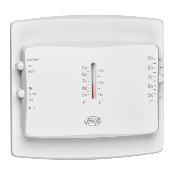
Set the switch to electric furnaces. 5. Insert two fresh AA alkaline batteries. 6. Align the thermostat with the the wall plate, and snap the two halves together. 7. restore power at the electrical panel or furnace. - Page 20 System Switch SYSTEM HEAT AUTO Battery Indicator Switch Set Temperature Thermometer Slider...
-
Page 21: Operation
1. Set the temperature. 2. The ystEm mode of the thermostat. Select 3. The witcH position. To run the fan continuously, slide the note: In operation of your system. In a normal gas or oil furnace, the fan will be turned on by your furnace after its warm-up delay. - Page 22 3. The second warning is the indicated by the approximately twice every second. When this warning appears, the thermostat is shut down and will turn your system OFF. Your system will remain shut-off until you install two fresh AA alkaline batteries.
- Page 23 Span Adjust SPAN...
-
Page 24: Indicators & Adjustments
InDICATOrS AnD ADjUSTMEnTS, COnT. Your thermostat is preset to cycle your system off and on at 1 F above and below the Set Temperature. For maximum system efficiency and a sustained comfortable temperature your system should cycle 3 - 5 times per hour. If your system is... - Page 25 1 c. replace the batteries with fresh AA alkaline batteries. 1 d. If applicable, make sure the furnace blower door is closed properly. 2. My system continues to operate when the thermostat is in the off position. 2 a. replace unit.
-
Page 26: Troubleshooting
TrOUBlESHOOTInG Is there help on the web? Yes. Visit http://www.hunterfan.com for more information. Can’t I just call someone? Sure. Our Technical Support Group is available from 8 am to 5 pm CST. They may be reached toll-free at1-888-830- 1326. -
Page 27: Wiring Diagrams
WIrInG DIAGrAMS 2- w i r e Heat Onl y Sys t em Heat Rel ay Heat 24V or or Val ve M i l l i vol t Suppl y 3- w i r e Heat Onl y Sys t em Rh W Heat 24V Suppl y... - Page 28 © 2007 Hunter Fan Company...
Need help?
Do you have a question about the 40120 and is the answer not in the manual?
Questions and answers