Toa VX-3000 Series Operating Instructions Manual
Integrated voice evacuation system
Hide thumbs
Also See for VX-3000 Series:
- Operating instructions manual (63 pages) ,
- User manual (8 pages) ,
- Installation manual (162 pages)
Table of Contents
Advertisement
Quick Links
Advertisement
Table of Contents

Subscribe to Our Youtube Channel
Related Manuals for Toa VX-3000 Series


Summary of Contents for Toa VX-3000 Series
- Page 1 OPERATING INSTRUCTIONS INTEGRATED VOICE EVACUATION SYSTEM VX-3000 SERIES VX-3004F VX-3000CT RM-200SF RM-300X RM-500 Thank you for purchasing TOA's Integrated Voice Evacuation System. Please carefully follow the instructions in this manual to ensure long, trouble-free use of your equipment.
-
Page 2: Table Of Contents
TABLE OF CONTENTS Chapter 1 : NOMENCLATURE 1. VX-3004F, VX-3008F, AND VX-3016F VOICE EVACUATION FRAME ............... 1-2 2. RM-200SF FIREMAN’S MICROPHONE AND RM-320F REMOTE MICROPHONE EXTENSION ........... 1-6 2.1. RM-200SF ......................1-6 2.2. RM-320F ......................1-8 3. RM-300X REMOTE MICROPHONE AND RM-210F REMOTE MICROPHONE EXTENSION ........... - Page 3 2.13. Indicator State at the Time of Emergency Sequence Stop ......2-22 2.14. Indicator State at the Time of Emergency Sequence Phase Shift ....2-23 2.15. Indicator State at the Time of Emergency Reset ........... 2-24 2.16. Indicator State at the Time of Emergency Broadcast Silence .......
- Page 4 4.7. Indicator State at the Time of Intended Control Input ........2-69 4.8. Indicator State at the Time of Intended Control Output (Pulse) ...... 2-70 4.9. Indicator State at the Time of Intended Control Output (Level) ....... 2-71 4.10. Indicator State at the Time of Zone Volume Adjustment (Pulse) ....
-
Page 5: Chapter 1 : Nomenclature
Chapter 1 NOMENCLATURE... -
Page 6: Vx-3004F, Vx-3008F, And Vx-3016F Voice Evacuation Frame
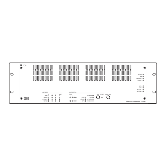
1. VX-3004F, VX-3008F, AND VX-3016F VOICE EVACUATION FRAME VX-3004F, VX-3008F, and VX-3016F are collectively referred to as “VX-3000F” in this manual. • The VX-3000F is a unit designed to control the Voice evacuation announcements of the VX-3000 series voice evacuation system. - Page 7 NOMENCLATURE Chapter 1 VX-3016F Amplifier section Fault status section [Amplifier section] [Fault status section] 21 22 23 1. Power indicator (Green) 7. RS link A indicator (Green) Lights when the power is supplied. Lights when the RS link A connector on the Flashes in standby state.
- Page 8 NOMENCLATURE Chapter 1 11. Amplifier operate indicators (Green) 15. Power fault indicator (Yellow) The indicator corresponding to the module slot Lights or flashes when failures are detected in port will light or go off depending on the operation Power Supply Manager. state ...
- Page 9 NOMENCLATURE Chapter 1 1. VX-3000CT CONTROL PANEL • The VX-3000CT is a 1U size* Control panel mountable in an EIA standard equipment rack. • Operation such as the activation of general broadcast and the input/output volume control can be performed by connecting the VX-3000CT to the VX-3000F via network.
-
Page 10: Rm-200Sf Fireman's Microphone And Rm-320F Remote Microphone Extension
NOMENCLATURE Chapter 1 2. RM-200SF FIREMAN’S MICROPHONE AND RM-320F REMOTE MICROPHONE EXTENSION 2.1. RM-200SF • The RM-200SF Fireman’s Microphone features 3 function keys, 1 emergency key, 1 talk key, and the indicator lamps associated with these keys. Functions are assigned to the function keys using the VX-3000 Setting Software. • Specially designed for both emergency and general purpose broadcast applications, the Fireman’s Microphone can be used for push-button zone selection and microphone broadcasts. •... - Page 11 NOMENCLATURE Chapter 1 8. Indication label insert slot 13. Selection indicators (Green) The label can be printed using the VX-3000 Light or go off depending on the current operation Setting Software. (See the separate Setting state of function keys. (See the Chapter 2.) Software Instructions, "PRINTING LABELS FOR REMOTE MICROPHONES.") 14.
-
Page 12: Rm-320F
NOMENCLATURE Chapter 1 2.2. RM-320F Each connected RM-320F Extension unit adds 20 Function keys to the base RM-200SF. [Front] 1. Connection cable 4. Selection indicators (Green) Used for connection to the RM-200SF or other Light or go off depending on the current operation RM-320F. -
Page 13: Rm-300X Remote Microphone And Rm-210F Remote Microphone Extension
NOMENCLATURE Chapter 1 3. RM-300X REMOTE MICROPHONE AND RM-210F REMOTE MICROPHONE EXTENSION 3.1. RM-300X • The RM-300X Remote Microphone features 13 function keys, 1 covered key, 1 talk key, and the indicator lamps associated with these. Functions are assigned to the function keys using the VX-3000 Setting Software. •... -
Page 14: Rm-210F
NOMENCLATURE Chapter 1 6. Indication label insert slots 10. Talk Key Labels can be printed using the VX-3000 Setting Press this key to broadcast a voice announcement. Software. (See the separate Setting Software If the Talk key is set to “PTT “ (“press-to-talk”) Instructions, "PRINTING LABELS FOR REMOTE mode, then it must be pressed continuously for MICROPHONES.") -
Page 15: Remote Microphone
NOMENCLATURE Chapter 1 4. RM-500 REMOTE MICROPHONE • The RM-500 is a desktop type remote microphone designed for general broadcast. • Equipped with an LCD screen, it can display up to 80 function names registered in advance, allowing these functions to be executed with the key operation. •... - Page 16 NOMENCLATURE Chapter 1 11. Talk key Press this key to broadcast a voice announcement. Press this key to move to the previous page from Set the key operation mode to either PTT or Lock the current page displayed on the LCD screen. at the system setup.
-
Page 17: Chapter 2 : Indicator Status Of Control Panel And Remote Microphones
Chapter 2 INDICATOR STATUS OF CONTROL PANEL AND REMOTE MICROPHONES... -
Page 18: Vx-3000Ct Control Panel
INDICATOR STATUS OF CONTROL PANEL AND REMOTE MICROPHONES Chapter 2 1. VX-3000CT CONTROL PANEL 1.1. Indicator State at the Time of Input Volume Adjustment When the input volume adjustment function has been assigned to the volume control knob, the Signal indicator allows you to check the audio signal state of the input channel assigned to the volume control knob. -
Page 19: Indicator State At The Time Of Zone Selection
INDICATOR STATUS OF CONTROL PANEL AND REMOTE MICROPHONES Chapter 2 1.3. Indicator State at the Time of Zone Selection When a zone selection (pattern or individual) function has been assigned to a function key, the 2 indicators to the left of the key indicate its zone selection and broadcast status. Note For instructions on assigning functions to function keys, see the separate Setting Software Instructions, "EVENT SETTINGS."... -
Page 20: Indicator State At The Time Of Base Pattern Change
INDICATOR STATUS OF CONTROL PANEL AND REMOTE MICROPHONES Chapter 2 1.4. Indicator State at the Time of Base Pattern Change When a Base pattern change function has been assigned to a function key, the 2 indicators to the left of the key indicate its pattern selection and broadcast status. -
Page 21: Indicator State At The Time Of General/Bgm Broadcast
INDICATOR STATUS OF CONTROL PANEL AND REMOTE MICROPHONES Chapter 2 1.6. Indicator State at the Time of General/BGM Broadcast When a general/BGM broadcast function has been assigned to a function key, the 2 indicators to the left of the key indicate its selection and broadcast status. Note For instructions on assigning functions to function keys, see the separate Setting Software Instructions, "EVENT SETTINGS."... -
Page 22: Indicator State At The Time Of Intended Control Input
INDICATOR STATUS OF CONTROL PANEL AND REMOTE MICROPHONES Chapter 2 1.7. Indicator State at the Time of Intended Control Input When an intended control input function has been assigned to a function key, the 2 indicators to the left of the key indicate its selection and control status. -
Page 23: Indicator State At The Time Of Intended Control Output (Pulse)
INDICATOR STATUS OF CONTROL PANEL AND REMOTE MICROPHONES Chapter 2 1.8. Indicator State at the Time of Intended Control Output (Pulse) When the intended control output (pulse) function is assigned to the function key, pressing this key turns ON the preset control output. It is turned OFF when this key is pressed again. When an intended control output (pulse) function has been assigned to a function key, the 2 indicators to the left of the key indicate its selection and control statuses. -
Page 24: Indicator State At The Time Of Zone Volume Adjustment (Pulse)
INDICATOR STATUS OF CONTROL PANEL AND REMOTE MICROPHONES Chapter 2 1.10. Indicator State at the Time of Zone Volume Adjustment (Pulse) When the Zone volume adjustment (Pulse) function is assigned to the function key, pressing this key increases or decreases the volume level of the preset zone by the set amount. Sound adjustment status can be checked by the indicators to the left of the function key. -
Page 25: Indicator State At The Time Of Input Volume Adjustment (Pulse)
INDICATOR STATUS OF CONTROL PANEL AND REMOTE MICROPHONES Chapter 2 1.11. Indicator State at the Time of Input Volume Adjustment (Pulse) When the Input volume adjustment (Pulse) function is assigned to the function key, pressing this key increases or decreases the volume level of the preset Input channel by the set amount. Sound adjustment status can be checked by the indicators to the left of the function key. -
Page 26: Indicator State At The Time Of Emergency Warning Broadcast
INDICATOR STATUS OF CONTROL PANEL AND REMOTE MICROPHONES Chapter 2 1.12. Indicator State at the Time of Emergency Warning Broadcast The emergency warning broadcast function can be assigned to the function key. Pressing this key activates the emergency warning broadcast. When this function has been assigned to a function key, the 2 indicators to the left of the key indicate its selection and broadcast status. -
Page 27: Indicator State At The Time Of Sleep Mode Power On
INDICATOR STATUS OF CONTROL PANEL AND REMOTE MICROPHONES Chapter 2 1.13. Indicator State at the Time of Sleep Mode Power On When the VX-3000 system is set to enable "Sleep mode function," the power on function can be assigned to a function key. -
Page 28: Rm-200Sf Fireman's Microphone And Rm-320F Remote Microphone Extension
INDICATOR STATUS OF CONTROL PANEL AND REMOTE MICROPHONES Chapter 2 2. RM-200SF FIREMAN’S MICROPHONE AND RM-320F REMOTE MICROPHONE EXTENSION 2.1. Indicator State at the Time of Zone Selection When a zone selection (pattern or individual) function has been assigned to a function key, the 2 indicators to the left of the key indicate its zone selection and broadcast status. -
Page 29: Talk Key Indicators
INDICATOR STATUS OF CONTROL PANEL AND REMOTE MICROPHONES Chapter 2 2.2. Talk Key Indicators Talk Key Broadcast Status Indicator Microphone Indicator Indicator meanings are as follows: Indicator Status Meaning Microphone Indicator Unlit Microphone not in use Lights green Microphone in use Flashes green Chime broadcast in progress from the primary Remote Microphone. -
Page 30: Indicator State At The Time Of Base Pattern Change
INDICATOR STATUS OF CONTROL PANEL AND REMOTE MICROPHONES Chapter 2 2.3. Indicator State at the Time of Base Pattern Change When a Base pattern change function has been assigned to a function key, the 2 indicators to the left of the key indicate its pattern selection and broadcast status. -
Page 31: Indicator State At The Time Of General/Bgm Broadcast
INDICATOR STATUS OF CONTROL PANEL AND REMOTE MICROPHONES Chapter 2 2.5. Indicator State at the Time of General/BGM Broadcast When a general/BGM broadcast function has been assigned to a function key, the 2 indicators to the left of the key indicate its selection and broadcast status. Note For instructions on assigning functions to function keys, see the separate Setting Software Instructions, "EVENT SETTINGS."... -
Page 32: Indicator State At The Time Of Lamp Test
INDICATOR STATUS OF CONTROL PANEL AND REMOTE MICROPHONES Chapter 2 2.7. Indicator State at the Time of Lamp Test When the lamp test function has been assigned to the Function key, the 2 indicators to the left of the key indicate the running status of the lamp test. -
Page 33: Indicator State At The Time Of Failure Output Receipt
INDICATOR STATUS OF CONTROL PANEL AND REMOTE MICROPHONES Chapter 2 2.8. Indicator State at the Time of Failure Output Receipt When the VX-3000 system is set to enable "Surveillance function," the failure output receipt function can be assigned to a function key. When the failure output receipt function has been assigned to the Function key, the 2 indicators to the left of the key indicate the occurrence and acknowledgement status of the failure output pattern. -
Page 34: Indicator State At The Time Of Failure Output Reset
INDICATOR STATUS OF CONTROL PANEL AND REMOTE MICROPHONES Chapter 2 2.9. Indicator State at the Time of Failure Output Reset When the VX-3000 system is set to enable "Surveillance function," the failure output reset function can be assigned to a function key. When the failure output reset function has been assigned to the Function key, the failure status indicator can be reset by pressing the key. -
Page 35: Indicator State At The Time Of Emergency Broadcast Pattern Start
INDICATOR STATUS OF CONTROL PANEL AND REMOTE MICROPHONES Chapter 2 2.10. Indicator State at the Time of Emergency Broadcast Pattern Start When the system is set to "Emergency," the emergency broadcast pattern start function can be assigned to the Emergency key or function key. Pressing the function-assigned key causes the emergency broadcast to start. -
Page 36: Indicator State At The Time Of Emergency Broadcast Pattern Stop
INDICATOR STATUS OF CONTROL PANEL AND REMOTE MICROPHONES Chapter 2 2.11. Indicator State at the Time of Emergency Broadcast Pattern Stop When the system is set to "Emergency," the emergency broadcast pattern stop function can be assigned to the Function key. Pressing the function-assigned key causes the emergency broadcast pattern to stop. -
Page 37: Indicator State At The Time Of Emergency Broadcast Pattern Start/Stop
INDICATOR STATUS OF CONTROL PANEL AND REMOTE MICROPHONES Chapter 2 2.12. Indicator State at the Time of Emergency Broadcast Pattern Start/Stop When the system is set to "Emergency," the emergency broadcast pattern start function can be assigned to the Emergency key or function key. When the Emergency Broadcast Pattern set to the function-assigned key is OFF, pressing this key activates the emergency broadcast. -
Page 38: Indicator State At The Time Of Emergency Sequence Stop
INDICATOR STATUS OF CONTROL PANEL AND REMOTE MICROPHONES Chapter 2 2.13. Indicator State at the Time of Emergency Sequence Stop When the system is set to "Emergency," the emergency sequence stop function can be assigned to the Function key. Pressing the function-assigned key causes all the emergency broadcast patterns including the set emergency sequence to stop. -
Page 39: Indicator State At The Time Of Emergency Sequence Phase Shift
INDICATOR STATUS OF CONTROL PANEL AND REMOTE MICROPHONES Chapter 2 2.14. Indicator State at the Time of Emergency Sequence Phase Shift When the system is set to "Emergency," the emergency sequence phase shift function can be assigned to a function key. Pressing the function-assigned key causes the set emergency sequence to shift to the next phase. -
Page 40: Indicator State At The Time Of Emergency Reset
INDICATOR STATUS OF CONTROL PANEL AND REMOTE MICROPHONES Chapter 2 2.15. Indicator State at the Time of Emergency Reset When the system is set to "Emergency," the emergency reset function can be assigned to the Function key. Pressing the function-assigned key causes all the activated emergency broadcast patterns to stop, allowing the emergency broadcast status to be reset after the restoration EV message broadcast completion. -
Page 41: Indicator State At The Time Of Emergency Broadcast Silence
INDICATOR STATUS OF CONTROL PANEL AND REMOTE MICROPHONES Chapter 2 2.16. Indicator State at the Time of Emergency Broadcast Silence When the system is set to "Emergency," the emergency broadcast silence function can be assigned to the function key. The emergency broadcast silence function is a function to mute the output of the EV sound sources of which audio source type is set to "Evacuate"... -
Page 42: Indicator State At The Time Of Emergency Ev Broadcast
INDICATOR STATUS OF CONTROL PANEL AND REMOTE MICROPHONES Chapter 2 2.17. Indicator State at the Time of Emergency EV Broadcast When the system is set to "Emergency," the emergency EV broadcast function can be assigned to the Emergency key or function key. Assigning the Emergency EV broadcast function to the key allows the EV sound source of which audio type is set to "Evacuate"... -
Page 43: Indicator State At The Time Of Emergency Acknowledge
INDICATOR STATUS OF CONTROL PANEL AND REMOTE MICROPHONES Chapter 2 2.18. Indicator State at the Time of Emergency Acknowledge When the system is set to "Emergency," the Emergency acknowledge function can be assigned to the Emergency key or function key. If the Emergency acknowledge function has been assigned to the key, the buzzer built in the remote microphone sounds when the emergency broadcast pattern assigned to this key turns ON. - Page 44 INDICATOR STATUS OF CONTROL PANEL AND REMOTE MICROPHONES Chapter 2 [When assigned to the function key] Emergency operation enable/disable indicator Function key Emergency Acknowledge Indicator (Emergency Acknowledge key) Indicator meanings are as follows: Indicator Status Meaning Emergency operation* Unlit When set to EMG enable operation ON* Emergency operation from this remote microphone is enable/disable indicator disabled.
-
Page 45: Indicator State At The Time Of Disablement Of Emg Control From Cin
INDICATOR STATUS OF CONTROL PANEL AND REMOTE MICROPHONES Chapter 2 2.19. Indicator State at the Time of Disablement of EMG Control from CIN When the system is set to "Emergency," the "disablement of EMG control from CIN" function can be assigned to the function key. -
Page 46: Indicator State At The Time Of Audio Monitor
INDICATOR STATUS OF CONTROL PANEL AND REMOTE MICROPHONES Chapter 2 2.20. Indicator State at the Time of Audio Monitor When an audio monitor function has been assigned to a function key, the 2 indicators to the left of the key indicate its selection and audio monitor status. -
Page 47: Indicator State At The Time Of Intended Control Input
INDICATOR STATUS OF CONTROL PANEL AND REMOTE MICROPHONES Chapter 2 2.21. Indicator State at the Time of Intended Control Input When an intended control input function has been assigned to a function key, the 2 indicators to the left of the key indicate its selection and control status. -
Page 48: Indicator State At The Time Of Intended Control Output (Pulse)
INDICATOR STATUS OF CONTROL PANEL AND REMOTE MICROPHONES Chapter 2 2.22. Indicator State at the Time of Intended Control Output (Pulse) When the intended control output (pulse) function is assigned to the function key, pressing this key turns ON the preset control output. It is turned OFF when this key is pressed again. When an intended control output (pulse) function has been assigned to a function key, the 2 indicators to the left of the key indicate its selection and control statuses. -
Page 49: Indicator State At The Time Of Intended Control Output (Level)
INDICATOR STATUS OF CONTROL PANEL AND REMOTE MICROPHONES Chapter 2 2.23. Indicator State at the Time of Intended Control Output (Level) When the intended control output (level) function is assigned to the function key, the preset control output is turned ON while this key is held down. It is turned OFF when this key is released. When an intended control output (level) function has been assigned to a function key, the 2 indicators to the left of the key indicate its selection and control statuses. -
Page 50: Indicator State At The Time Of Zone Volume Adjustment (Pulse)
INDICATOR STATUS OF CONTROL PANEL AND REMOTE MICROPHONES Chapter 2 2.24. Indicator State at the Time of Zone Volume Adjustment (Pulse) When the Zone volume adjustment (Pulse) function is assigned to the function key, pressing this key increases or decreases the volume level of the preset zone by the set amount. Sound adjustment status can be checked by the indicators to the left of the function key. -
Page 51: Indicator State At The Time Of Input Volume Adjustment (Pulse)
INDICATOR STATUS OF CONTROL PANEL AND REMOTE MICROPHONES Chapter 2 2.25. Indicator State at the Time of Input Volume Adjustment (Pulse) When the Input volume adjustment (Pulse) function is assigned to the function key, pressing this key increases or decreases the volume level of the preset Input channel by the set amount. Sound adjustment status can be checked by the indicators to the left of the function key. -
Page 52: Indicator State At The Time Of Emergency Warning Broadcast
INDICATOR STATUS OF CONTROL PANEL AND REMOTE MICROPHONES Chapter 2 2.26. Indicator State at the Time of Emergency Warning Broadcast The emergency warning broadcast function can be assigned to the Emergency key or function key. Pressing this key activates the emergency warning broadcast. When the Emergency key is assigned this function, the key indicate its broadcast status. -
Page 53: Indicator State At The Time Of Sleep Mode Power On
INDICATOR STATUS OF CONTROL PANEL AND REMOTE MICROPHONES Chapter 2 2.27. Indicator State at the Time of Sleep Mode Power On When the VX-3000 system is set to enable "Sleep mode function," the power on function can be assigned to a function key. -
Page 54: Rm-300X Remote Microphone And Rm-210F Remote Microphone Extension
INDICATOR STATUS OF CONTROL PANEL AND REMOTE MICROPHONES Chapter 2 3. RM-300X REMOTE MICROPHONE AND RM-210F REMOTE MICROPHONE EXTENSION 3.1. Indicator State at the Time of Zone Selection When a zone selection (pattern or individual) function has been assigned to a function key, the 2 indicators to the left of the key indicate its zone selection and broadcast status. -
Page 55: Talk Key Indicators
INDICATOR STATUS OF CONTROL PANEL AND REMOTE MICROPHONES Chapter 2 3.2. Talk Key Indicators Broadcast Status Indicator Microphone Indicator Talk Key Indicator meanings are as follows: Indicator Status Meaning Microphone Indicator Unlit Microphone not in use Lights green Microphone in use Flashes green Chime broadcast in progress from the primary Remote Microphone. -
Page 56: Indicator State At The Time Of General-Purpose Broadcast Pattern
INDICATOR STATUS OF CONTROL PANEL AND REMOTE MICROPHONES Chapter 2 3.4. Indicator State at the Time of General-Purpose Broadcast Pattern When a general-purpose broadcast pattern function has been assigned to a function key, the 2 indicators to the left of the key indicate its pattern selection and broadcast status. Note For instructions on assigning functions to function keys, see the separate Setting Software Instructions, "EVENT SETTINGS."... -
Page 57: Indicator State At The Time Of Rm Broadcast Status Display
INDICATOR STATUS OF CONTROL PANEL AND REMOTE MICROPHONES Chapter 2 3.6. Indicator State at the Time of RM Broadcast Status Display The Broadcast status indicator to the left of the Function key indicates the current broadcast status of other Remote Microphone. Note For instructions on assigning functions to function keys, see the separate Setting Software Instructions, "EVENT SETTINGS."... -
Page 58: Indicator State At The Time Of Failure Output Receipt
INDICATOR STATUS OF CONTROL PANEL AND REMOTE MICROPHONES Chapter 2 3.8. Indicator State at the Time of Failure Output Receipt When the VX-3000 system is set to enable "Surveillance function," the failure output receipt function can be assigned to a function key. When the failure output receipt function has been assigned to the Function key, the 2 indicators to the left of the key indicate the occurrence and failure output receipt status of the failure output pattern. -
Page 59: Indicator State At The Time Of Failure Output Reset
INDICATOR STATUS OF CONTROL PANEL AND REMOTE MICROPHONES Chapter 2 3.9. Indicator State at the Time of Failure Output Reset When the VX-3000 system is set to enable "Surveillance function," the failure output reset function can be assigned to a function key. When the failure output reset function has been assigned to the Function key, the failure status indicator can be reset by pressing the key. -
Page 60: Indicator State At The Time Of Emergency Broadcast Pattern Start
INDICATOR STATUS OF CONTROL PANEL AND REMOTE MICROPHONES Chapter 2 3.10. Indicator State at the Time of Emergency Broadcast Pattern Start When the system is set to "Emergency" and the type of the RM-300X to "Emergency" or "Emergency/General," the emergency broadcast pattern start function can be assigned to the covered key or Function key. Pressing the function-assigned key causes the emergency to start. -
Page 61: Indicator State At The Time Of Emergency Broadcast Pattern Stop
INDICATOR STATUS OF CONTROL PANEL AND REMOTE MICROPHONES Chapter 2 3.11. Indicator State at the Time of Emergency Broadcast Pattern Stop When the system is set to "Emergency" and the type of the RM-300X to "Emergency" or "Emergency/General," the emergency broadcast pattern stop function can be assigned to the Function key. Pressing the function-assigned key causes the emergency broadcast pattern to stop. -
Page 62: Indicator State At The Time Of Emergency Broadcast Pattern Start/Stop
INDICATOR STATUS OF CONTROL PANEL AND REMOTE MICROPHONES Chapter 2 3.12. Indicator State at the Time of Emergency Broadcast Pattern Start/Stop When the system is set to "Emergency" and the type of the RM-300X to "Emergency" or "Emergency/General," the emergency broadcast pattern start/stop function can be assigned to the covered key or Function key. When the Emergency Broadcast Pattern set to the function-assigned key is OFF, pressing this key activates the emergency broadcast. -
Page 63: Indicator State At The Time Of Emergency Sequence Stop
INDICATOR STATUS OF CONTROL PANEL AND REMOTE MICROPHONES Chapter 2 [When assigned to the function key] Key ON/OFF Indicator Function key Emergency Broadcast State Indicator (Emergency broadcast pattern start/stop key) Indicator meanings are as follows: Indicator Status Meaning Key ON/OFF Indicator Unlit When the function key is not pressed Lights green... -
Page 64: Indicator State At The Time Of Emergency Sequence Phase Shift
INDICATOR STATUS OF CONTROL PANEL AND REMOTE MICROPHONES Chapter 2 3.14. Indicator State at the Time of Emergency Sequence Phase Shift When the system is set to "Emergency" and the type of the RM-300X to "Emergency" or "Emergency/General," the emergency sequence phase shift function can be assigned to a function key. Assigning this function to the Function key causes the 2 indicators next to the Function key to indicate the emergency sequence phase state. -
Page 65: Indicator State At The Time Of Emergency Reset
INDICATOR STATUS OF CONTROL PANEL AND REMOTE MICROPHONES Chapter 2 3.15. Indicator State at the Time of Emergency Reset When the system is set to "Emergency" and the type of the RM-300X to "Emergency" or "Emergency/General," the emergency reset function can be assigned to a function key. Pressing the function-assigned key causes all the activated emergency broadcast patterns to stop, allowing the emergency broadcast status to be reset after the restoration EV message broadcast completion. -
Page 66: Indicator State At The Time Of Emergency Broadcast Silence
INDICATOR STATUS OF CONTROL PANEL AND REMOTE MICROPHONES Chapter 2 3.16. Indicator State at the Time of Emergency Broadcast Silence When the system is set to "Emergency" and the type of the RM-300X to "Emergency" or "Emergency/General," the emergency broadcast silence function can be assigned to the Function key. The emergency broadcast silence function is a function to mute the output of the EV sound sources of which audio source type is set to "Evacuate"... -
Page 67: Indicator State At The Time Of Emergency Ev Broadcast
INDICATOR STATUS OF CONTROL PANEL AND REMOTE MICROPHONES Chapter 2 3.17. Indicator State at the Time of Emergency EV Broadcast When the system is set to "Emergency" and the type of the RM-300X to "Emergency" or "Emergency/General," the emergency EV broadcast function can be assigned to the covered key or Function key. Assigning the Emergency EV broadcast function to the key allows the EV sound source of which audio type is set to "Evacuate"... -
Page 68: Indicator State At The Time Of Emergency Acknowledge
INDICATOR STATUS OF CONTROL PANEL AND REMOTE MICROPHONES Chapter 2 3.18. Indicator State at the Time of Emergency Acknowledge When the system is set to "Emergency" and the type of the RM-300X to "Emergency" or "Emergency/General," the emergency EV broadcast function can be assigned to the covered key or Function key. If the Emergency acknowledge function has been assigned to the key, the buzzer built in the remote microphone sounds when the emergency broadcast pattern assigned to this key turns ON. - Page 69 INDICATOR STATUS OF CONTROL PANEL AND REMOTE MICROPHONES Chapter 2 [When assigned to the function key] Emergency operation enable/disable indicator Function key Emergency Acknowledge Indicator (Emergency Acknowledge key) Indicator meanings are as follows: Indicator Status Meaning Emergency operation* Unlit When set to EMG enable operation ON* Emergency operation from this remote microphone is enable/disable indicator disabled.
-
Page 70: Indicator State At The Time Of Disablement Of Emg Control From Cin
INDICATOR STATUS OF CONTROL PANEL AND REMOTE MICROPHONES Chapter 2 3.19. Indicator State at the Time of Disablement of EMG Control from CIN When the system is set to "Emergency" and the type of the RM-300X to "Emergency" or "Emergency/General," the "disablement of EMG control from CIN"... -
Page 71: Indicator State At The Time Of Audio Monitor
INDICATOR STATUS OF CONTROL PANEL AND REMOTE MICROPHONES Chapter 2 3.20. Indicator State at the Time of Audio Monitor When an audio monitor function has been assigned to a function key, the 2 indicators to the left of the key indicate its selection and audio monitor statuses. -
Page 72: Indicator State At The Time Of Intended Control Output (Pulse)
INDICATOR STATUS OF CONTROL PANEL AND REMOTE MICROPHONES Chapter 2 3.22. Indicator State at the Time of Intended Control Output (Pulse) When the intended control output (pulse) function is assigned to the function key, pressing this key turns ON the preset control output. It is turned OFF when this key is pressed again. When an intended control output (pulse) function has been assigned to a function key, the 2 indicators to the left of the key indicate its selection and control statuses. -
Page 73: Indicator State At The Time Of Zone Volume Adjustment (Pulse)
INDICATOR STATUS OF CONTROL PANEL AND REMOTE MICROPHONES Chapter 2 3.24. Indicator State at the Time of Zone Volume Adjustment (Pulse) When the Zone volume adjustment (Pulse) function is assigned to the function key, pressing this key increases or decreases the volume level of the preset zone by the set amount. Sound adjustment status can be checked by the indicators to the left of the function key. -
Page 74: Indicator State At The Time Of Input Volume Adjustment (Pulse)
INDICATOR STATUS OF CONTROL PANEL AND REMOTE MICROPHONES Chapter 2 3.25. Indicator State at the Time of Input Volume Adjustment (Pulse) When the Input volume adjustment (Pulse) function is assigned to the function key, pressing this key increases or decreases the volume level of the preset Input channel by the set amount. Sound adjustment status can be checked by the indicators to the left of the function key. -
Page 75: Indicator State At The Time Of Emergency Warning Broadcast
INDICATOR STATUS OF CONTROL PANEL AND REMOTE MICROPHONES Chapter 2 3.26. Indicator State at the Time of Emergency Warning Broadcast The emergency warning broadcast function can be assigned to the covered key or function key. Pressing this key activates the emergency warning broadcast. When the covered key is assigned this function, a indicator to the left of the key indicate its broadcast statuses. -
Page 76: Indicator State At The Time Of Sleep Mode Power On
INDICATOR STATUS OF CONTROL PANEL AND REMOTE MICROPHONES Chapter 2 3.27. Indicator State at the Time of Sleep Mode Power On When the VX-3000 system is set to enable "Sleep mode function," the power on function can be assigned to a function key. -
Page 77: Rm-500'S Lcd Screen Display
INDICATOR STATUS OF CONTROL PANEL AND REMOTE MICROPHONES Chapter 2 4. RM-500’S LCD SCREEN DISPLAY In normal use state, the following contents are displayed on the LCD screen. Room 1 BGM 1 Room 2 BGM 2 Room 3 BGM stop Room 4 Volume up Room 5... - Page 78 INDICATOR STATUS OF CONTROL PANEL AND REMOTE MICROPHONES Chapter 2 [Broadcast status display list] Broadcast status Meaning of display Broadcast: n* Broadcast is being made from this unit to the broadcast destination set in the function display on the LCD screen. In this case, the display area is highlighted (example: Broadcast: 1 Broadcast: All Broadcast is being made from this unit to the broadcast destination set in the ALL key.
-
Page 79: Indicator State At The Time Of Zone Selection
INDICATOR STATUS OF CONTROL PANEL AND REMOTE MICROPHONES Chapter 2 4.1. Indicator State at the Time of Zone Selection When a zone selection (pattern or individual) function has been assigned to a function display, the displays of the function display area and individual icon display area indicate its zone selection and broadcast status. Note For instructions on assigning functions to function displays, see the separate Setting Software Instructions, "EVENT SETTINGS."... -
Page 80: Talk Indicator And Microphone Indicator
INDICATOR STATUS OF CONTROL PANEL AND REMOTE MICROPHONES Chapter 2 4.2. Talk Indicator and Microphone Indicator Talk indicator Microphone indicator Talk key Indicator meanings are as follows: Indicator Status Meaning Microphone Indicator Unlit When the Talk key is not operated When microphone announcements are being made from the microphone connected to the AUX input terminal When the Microphone indicator is set to "OFF"... -
Page 81: Indicator State At The Time Of Base Pattern Change
INDICATOR STATUS OF CONTROL PANEL AND REMOTE MICROPHONES Chapter 2 4.3. Indicator State at the Time of Base Pattern Change When a Base pattern change function has been assigned to a function display, the displays of the function display area and individual icon display area indicate its pattern selection and broadcast status. Note For instructions on assigning functions to function displays, see the separate Setting Software Instructions, "EVENT SETTINGS."... -
Page 82: Indicator State At The Time Of General-Purpose Broadcast Pattern
INDICATOR STATUS OF CONTROL PANEL AND REMOTE MICROPHONES Chapter 2 4.4. Indicator State at the Time of General-Purpose Broadcast Pattern When a general-purpose broadcast pattern function has been assigned to a function display, the displays of the function display area and individual icon display area indicate its pattern selection and broadcast status. Note For instructions on assigning functions to function displays, see the separate Setting Software Instructions, "EVENT SETTINGS."... -
Page 83: Indicator State At The Time Of General/Bgm Broadcast
INDICATOR STATUS OF CONTROL PANEL AND REMOTE MICROPHONES Chapter 2 4.5. Indicator State at the Time of General/BGM Broadcast When a general/BGM broadcast function has been assigned to a function display, the displays of the function display area and individual icon display area indicate its selection and broadcast statuses. Note For instructions on assigning functions to function displays, see the separate Setting Software Instructions, "EVENT SETTINGS."... -
Page 84: Indicator State At The Time Of Rm Broadcast Status Display
INDICATOR STATUS OF CONTROL PANEL AND REMOTE MICROPHONES Chapter 2 4.6. Indicator State at the Time of RM Broadcast Status Display When an RM broadcast status display function has been assigned to a function display the display of the icon display area indicates the current broadcast status of other Remote Microphone. -
Page 85: Indicator State At The Time Of Intended Control Input
INDICATOR STATUS OF CONTROL PANEL AND REMOTE MICROPHONES Chapter 2 4.7. Indicator State at the Time of Intended Control Input When an intended control input function has been assigned to a function display, the displays of the function display area and individual icon display area indicate its selection and control statuses. Notes •... -
Page 86: Indicator State At The Time Of Intended Control Output (Pulse)
INDICATOR STATUS OF CONTROL PANEL AND REMOTE MICROPHONES Chapter 2 4.8. Indicator State at the Time of Intended Control Output (Pulse) When the intended control output (pulse) function is assigned to the function display, selecting this display turns ON the preset control output. It is turned OFF when this display is selected again. When an intended control output (pulse) function has been assigned to a function display, the displays of the function display area and individual icon display area indicate its selection and control statuses. -
Page 87: Indicator State At The Time Of Intended Control Output (Level)
INDICATOR STATUS OF CONTROL PANEL AND REMOTE MICROPHONES Chapter 2 4.9. Indicator State at the Time of Intended Control Output (Level) When an intended control output (LEVEL) function has been assigned to a function display on the LCD screen, the preset control output is turned on only while the numeric key corresponding to this function display is being pressed. -
Page 88: Indicator State At The Time Of Zone Volume Adjustment (Pulse)
INDICATOR STATUS OF CONTROL PANEL AND REMOTE MICROPHONES Chapter 2 4.10. Indicator State at the Time of Zone Volume Adjustment (Pulse) When the Zone volume adjustment (Pulse) function is assigned to the function display, selecting this display increases or decreases the volume level of the preset zone by the set amount. You can check the volume adjustment state that is displayed in the lower part of the LCD screen. -
Page 89: Indicator State At The Time Of Input Volume Adjustment (Pulse)
INDICATOR STATUS OF CONTROL PANEL AND REMOTE MICROPHONES Chapter 2 4.11. Indicator State at the Time of Input Volume Adjustment (Pulse) When the Input volume adjustment (Pulse) function is assigned to the function display, selecting this display increases or decreases the volume level of the preset Input channel by the set amount. You can check the volume adjustment state that is displayed in the lower part of the LCD screen. -
Page 90: Indicator State At The Time Of Emergency Warning Broadcast
INDICATOR STATUS OF CONTROL PANEL AND REMOTE MICROPHONES Chapter 2 4.12. Indicator State at the Time of Emergency Warning Broadcast The emergency warning broadcast function can be assigned to the function display. Selecting this display activates the emergency warning broadcast. When an emergency warning broadcast function has been assigned to a function display, the displays of the function display area and individual icon display area indicate its selection and broadcast statuses. -
Page 91: Indicator State At The Time Of Sleep Mode Power On
INDICATOR STATUS OF CONTROL PANEL AND REMOTE MICROPHONES Chapter 2 4.13. Indicator State at the Time of Sleep Mode Power On When the VX-3000 system is set to enable "Sleep mode function," the power on function can be assigned to a function display. -
Page 92: Chapter 3 : Operation
Chapter 3 OPERATION... -
Page 93: Bgm And General Broadcast
OPERATION Chapter 3 1. BGM AND GENERAL BROADCAST 1.1. Broadcasting from the Remote Microphone or the Control Panel The function keys of the RM-200SF/320F/300X/210F/500 Remote microphone can be used to make microphone announcements, to change or end BGM broadcasts, and to activate or end general-purpose and general/BGM broadcasts. -
Page 94: Operation Examples
OPERATION Chapter 3 1.3. Operation Examples 1.3.1. Example of microphone announcements made to the selected (pattern-designated) zones Broadcast status indicator Step 1. Press Function key R1 (Zones 1, 2 and 3). Zone selection indicator All of the designated zones are selected, and the zone selection indicator next to Function key R1 lights Function key green. - Page 95 OPERATION Chapter 3 1.3.2. Example of microphone announcements made to the selected (individual) zones Step 1. Press Function key R2 (Zone 1) and Function key R3 Broadcast status indicator (Zone 2). Zone selection indicator Zones 1 and 2 are selected, and their zone selection indicators light green.
- Page 96 OPERATION Chapter 3 1.3.3. Example of microphone announcements made to the preset zones You can make broadcasts from the remote microphone to the preset zones only by pressing the Talk key if you assign the broadcast zone pattern or individual zone to the Talk key in advance. Note For instructions on assigning zone pattern or individual zone to talk key, see the separate Setting Software Instructions, "EVENT SETTINGS."...
- Page 97 OPERATION Chapter 3 1.3.4. Example of BGM broadcasting Following is the operation example in the case where BGM broadcast is made by the BGM pattern 1 in the morning and changed to the BGM pattern 2 in the afternoon, and then ended. Step 1.
- Page 98 OPERATION Chapter 3 1.3.6. Example of general/BGM broadcasting Here, an operation example based on the zone patterns is explained. Step 1. Press the function key R1 (Zones 1, 2, and 3). Broadcast status indicator All the set zones are selected, and the zone Zone selection indicator selection indicator of the function key R1 lights green.
- Page 99 OPERATION Chapter 3 1.3.8. Example of input volume adjustment [When increasing the volume level of the preset input channel] Step: Press the function key 11 (Input 1 volume up) several Volume indicator times until the volume becomes the desired level. Function key Each time the key is pressed, the volume level of the set input channel increases by the set amount.
-
Page 100: Emergency Warning Broadcast
OPERATION Chapter 3 1.4. Emergency Warning Broadcast You can start an emergency warning broadcast using the remote microphone’s key or the control panel’s function key. The preset audio source applied to the VX-3000F’s Audio input can be broadcast to the preset zones while the key is held down. Emergency warning broadcast can be made even during power failure. When attenuators are used in the broadcast zones, the emergency warning broadcast is made bypassing the attenuators and signal processing. -
Page 101: Operation Of The
OPERATION Chapter 3 2. OPERATION OF THE RM-500 2.1. Selecting Items on the LCD Screen A list of pre-registered functions is displayed on the RM-500’s LCD screen. Room 1 BGM 1 Room 2 BGM 2 Room 3 BGM stop Room 4 Volume up Room 5 Volume down 1 / 8 Broadcast: F1 F2 Clear key Step 1. -
Page 102: Making Microphone Announcements
OPERATION Chapter 3 2.2. Making Microphone Announcements 2.2.1. When making the microphone announcements by selecting the broadcast zone(s) Step 1. Select the broadcast zone(s). 1-1. When making broadcast by selecting the individual zone(s) or pattern Select the zone(s) from the function list displayed on the LCD screen. (See "Selecting Items on the LCD Screen"... - Page 103 OPERATION Chapter 3 2.2.2. Example of microphone announcements made to the preset zones You can make broadcasts from the remote microphone to the preset zones only by pressing the Talk key if you assign the broadcast zone pattern or individual zone to the Talk key in advance. Step 1.
-
Page 104: Making Microphone Announcements In Direct Selection Mode
OPERATION Chapter 3 2.3. Making Microphone Announcements in Direct Selection Mode When set to the Direct selection mode, the selection method of the broadcast zones changes as described below. Step 1. Press the numeric key to enter the line number for which 00-00 Direct mode you wish to make broadcast. -
Page 105: Making The Aux Broadcast
OPERATION Chapter 3 2.4. Making the AUX Broadcast When the AUX key is assigned the general broadcast pattern that uses the own unit’s AUX input as audio source or the general/BGM broadcast, you can make broadcast the audio signals applied to the AUX input. If the AUX key is set active, the indication ”AUX"... -
Page 106: Activating Various Functions
OPERATION Chapter 3 2.5. Activating Various Functions The functions shown below can be set as selectable items on the LCD screen. Activate general broadcast pattern, Activate base broadcast pattern, Interrupt base broadcast pattern, Zone volume adjustment (Pulse), Input volume adjustment (Pulse), Emergency warning broadcast, RM broadcast status, Activate general/BGM broadcast, Pre select (Pattern), Pre select (Individual), Clear pre selected zones, Intended control input operation, Intended control output operation (Pulse), Intended control output operation (Level), Power on... -
Page 107: Locking Keys
OPERATION Chapter 3 2.6. Locking Keys You can use the Key lock function when you set the Key lock function to "Use." (See the separate Installation Manual, "Setting The RM-500’s Menu.") By locking the key, you can disable other operations than the key unlock operation. The indication "Key lock"... -
Page 108: Emergency Broadcast
OPERATION Chapter 3 3. EMERGENCY BROADCAST 3.1. Typical System Examples Here, an example of sequential operation with the VX-3000 system is explained. [Sequential Operation] Sequential operation consists of Phase 1 and Phase 2. Sequence Phase 1 operates upon emergency system activation. When the set time interval elapses, the broadcast is automatically switched to Phase 2. - Page 109 OPERATION Chapter 3 Step 3. Following this, sensors Signal added to A-2F and A-4F installed on A-2F and A-4F detect irregularities and the fire alarm system transmits a control signal to the control input. Emergency Broadcast zones are added, and sequence the alert message is also broadcast Phase 1...
-
Page 110: Remote Microphone Operation Example
OPERATION Chapter 3 3.2. Remote Microphone Operation Example The emergency mode can be activated and restored not only from the connected fire alarm system, but also from any Remote Microphone set for emergency or emergency/general-purpose operation. Here, the settings of the Fireman's Microphone RM-200SF installed on GF of Building A are used as an example to explain the flow from emergency mode activation to its restoration. [Setting Contents of Fireman's Microphone] RM-200SF RM-320F RM-200SF... - Page 111 OPERATION Chapter 3 [Operation example 1] Described below are the steps of system operation from emergency mode activation to restoration. Step 1. Press the Emergency key (1). Emergency key • Emergency mode is activated and the Emergency key lights red. • The ...
- Page 112 OPERATION Chapter 3 Step 3. When making broadcast using the RM-200SF, follow the procedures below. Zone monitor indicator Selection indicator • Press the All-Zone Call key (4) to select all zones. In this event, the Selection indicator lights. All-Zone Call key Green Talk key •...
- Page 113 OPERATION Chapter 3 [Operation example 2 (Example of emergency EV broadcasting)] When the system is in emergency mode, an emergency EV message can be broadcast to the zones after you designate them. Note It is not possible to broadcast the Emergency EV message even if the operation below is executed during general mode.
- Page 114 OPERATION Chapter 3 [Operation example 4 (Example of disablement of EMG control from CIN: Basic operation)] You can stop the emergency activation from the control input when the system is in general mode. This function is intended not to activate the emergency broadcast by the fire alarm system during maintenance. Note This function is enabled only when the system is in general mode.
- Page 115 OPERATION Chapter 3 [Operation example 5 (Example of disablement of EMG control from CIN: Operation when the function is turned ON by other remote microphone)] When the "Disablement of EMG control from CIN" key is assigned Status indicator of "disablement of EMG control from CIN"...
-
Page 116: Making All-Zone Emergency Broadcast
OPERATION Chapter 3 4. MAKING ALL-ZONE EMERGENCY BROADCAST If normal broadcasts cannot be made due to system failure or some trouble, only an all-call is possible. This is a broadcast made by bypassing the CPU* that normally operates in the VX-3000 system. (For details, see the separate Installation Manual, "INSTALLATION AND SETTING PROCEDURES.") This broadcast is called "All-zone emergency broadcast."... -
Page 117: Making All-Zone Emergency Broadcast From The Rm-300X
OPERATION Chapter 3 4.2. Making All-zone Emergency Broadcast from the RM-300X Open the cover of the All-zone Emergency Broadcast key, then while holding down the key, wait about 4 seconds until the Failure indicator lights red and begin to make microphone announcements. Failure Indicator Cover Lights red... -
Page 118: Making All-Zone Emergency Broadcast From The Rm-200Sf
OPERATION Chapter 3 4.3. Making All-zone Emergency Broadcast from the RM-200SF Step 1. Set the CPU switch on the front surface to OFF. RM-200SF front Tip: The CPU switch is factory-preset to ON. RM-200SF FIREMAN'S MICROPHONE RM-200SF rear Notes • The RM-200SF's DIP switch 6 (factory default: ON) must be preset to ON to enable the CPU OFF function (all-zone emergency broadcast). -
Page 119: Detecting Fault
OPERATION Chapter 3 5. DETECTING FAULT If a malfunction occurs within the VX-3000 system, the fault state can be indicated, acknowledged or reset using the following keys or control terminals. • FAULT ACK and FAULT RESET keys on the VX-3004F, VX-3008F, and VX-3016F •... -
Page 120: Case Example Of Malfunction
OPERATION Chapter 3 [Remote Microphone's Function key setting] RM-200SF Set function RM-200SF FIREMAN'S MICROPHONE (Not set) Talk key (fixed) Zone Clear Failure Output Reset Lamp Test RM-320F Set function Contents (failure pattern) Failure Output Receipt VX-3004F Failure Output Receipt Amplifier ZONE GF Failure Output Receipt Amplifier ZONE 1F Failure Output Receipt Amplifier ZONE 2F... -
Page 121: Remote Microphone's Operation Example
OPERATION Chapter 3 5.3. Remote Microphone's Operation Example When the failure is detected, the buzzer built in the remote Failure output receipt state indicator microphone sounds, and the Zone 2F failure output receipt state indicator flashes yellow. Key ON/OFF indicator Failure output receipt key Flashes yellow Step 1. -
Page 122: Vx-3004F's Operation Example
OPERATION Chapter 3 5.4. VX-3004F's Operation Example When the failure is detected, the built-in buzzer sounds, and the General fault indicator on the front panel flashes. In the case of the malfunction example on 3-29, both the Zone fault indicator 3 and the unit failure indicator corresponding to the fault point flash yellow. -
Page 123: Example Of Executing The Failure Reception And Failure Reset By Way Of The Control Input Terminals
OPERATION Chapter 3 Step 3. Press the Fault reset key. The General fault indicator goes off, and the VX-3000 system returns to normal state. Note Use a fine-tipped object to press the Fault reset key. 5.5. Example of Executing the Failure Reception and Failure Reset by Way of the Control Input Terminals Assign the failure reception and failure reset functions to the control input terminals on the rear panel of the VX-3004F, VX-3008F, and VX-3016F in advance. -
Page 124: Lamp Test
OPERATION Chapter 3 6. LAMP TEST Operation of audio monitor and control input/output can be performed using the remote microphone’s function key. Functions other than the audio monitor shown in the table below can also be operated with the function keys on the control panel. 6.1. Remote Microphone's Operation Example [Remote Microphone's Function key setting] RM-200SF RM-320F Set function... -
Page 125: Vx-3004F's Operation Example
OPERATION Chapter 3 6.2. VX-3004F's Operation Example Step 1. Continuously press the Lamp test key. All indicators light, and the buzzer built in the VX-3004F sounds. VX-3004F Step 2. Confirm that the indicators and buzzer operate correctly as in Step 1. Step 3. Release the Lamp test key to finish the lamp test. 3-34... -
Page 126: Other Functions
OPERATION Chapter 3 7. OTHER FUNCTIONS Operation of audio monitor and control input/output can be performed using the remote microphone’s function key. Functions other than the audio monitor shown in the table below can also be operated with the function keys on the control panel. [Setting example to function keys of the remote microphone] Item Name Function Function key R7... -
Page 127: Audio Monitor
OPERATION Chapter 3 7.1. Audio Monitor Audio signals during broadcast can be monitored by the remote microphone (except the RM-500). Broadcast status indicator Step 1. Press the Audio monitor key. The Broadcast status indicator lights green while Selection indicator audio signals are broadcast to the zone assigned to Function key this function key. -
Page 128: Intended Control Input Operation
OPERATION Chapter 3 7.2. Intended Control Input Operation The Intended control input of the VX-3000F and VX-3000PM can be operated using the Remote microphone's function key. In the same manner, this operation can also be performed with the function key on the control panel. -
Page 129: Intended Control Output Operation (Level)
OPERATION Chapter 3 7.4. Intended Control Output Operation (Level) The intended control output of the VX-3000F and VX-3000PM can be operated using the Remote microphone's function key. In the same manner, this operation can also be performed with the function key on the control panel. Step 1. -
Page 130: Switching Vx-3000 Amplifier's Power State Between Active (On) And Sleep Modes
Even if the sleep shift time has been set, you can forcibly Function key return the amplifier to the sleep mode during the duration of the set time. Traceability Information for Europe Manufacturer: Authorized representative: TOA Corporation TOA Electronics Europe GmbH 7-2-1, Minatojima-Nakamachi, Chuo-ku, Kobe, Hyogo, Suederstrasse 282, 20537 Hamburg, Japan Germany URL: https://www.toa.jp/ 202203...
Need help?
Do you have a question about the VX-3000 Series and is the answer not in the manual?
Questions and answers