Toa VX-3000 SERIES Operating Instructions Manual
Integrated voice evacuation system
Hide thumbs
Also See for VX-3000 SERIES:
- User manual (8 pages) ,
- Installation manual (162 pages) ,
- Operating instructions manual (130 pages)
Table of Contents
Advertisement
Advertisement
Table of Contents

Related Manuals for Toa VX-3000 SERIES


Summary of Contents for Toa VX-3000 SERIES
- Page 1 OPERATING INSTRUCTIONS INTEGRATEd VOICE EVACUATION SYSTEM VX-3000 SERIES VX-3004F RM-200SF RM-300X Thank you for purchasing TOA's Integrated Voice Evacuation System. Please carefully follow the instructions in this manual to ensure long, trouble-free use of your equipment.
-
Page 2: Table Of Contents
TABLE OF CONTENTS Chapter 1 : NOMENCLATURE 1. VX-3004F, VX-3008F, ANd VX-3016F VOICE EVACUATION FRAME ............... 1-2 2. RM-200SF FIREMAN’S MICROPHONE ANd RM-320F REMOTE MICROPHONE EXTENSION ..... 1-5 2.1. RM-200SF ......................1-5 2.2. RM-320F ......................1-7 3. RM-300X REMOTE MICROPHONE ANd RM-210F REMOTE MICROPHONE EXTENSION ..... - Page 3 2.9. Indicator State at the Time of Failure Output Reset ......... 2-20 2.10. Indicator State at the Time of Emergency Broadcast Pattern Start ....2-21 2.11. Indicator State at the Time of Emergency Broadcast Pattern Stop ....2-22 2.12. Indicator State at the Time of Emergency Sequence Stop ......
-
Page 4: Chapter 1 : Nomenclature
Chapter 1 NOMENCLATURE... -
Page 5: Vx-3004F, Vx-3008F, And Vx-3016F Voice Evacuation Frame
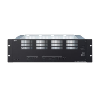
NOMENCLATURE Chapter 1 1. VX-3004F, VX-3008F, ANd VX-3016F VOICE EVACUATION FRAME VX-3004F, VX-3008F, and VX-3016F are collectively referred to as “VX-3000F” in this manual. • The VX-3000F is a unit designed to control the Voice evacuation announcements of the VX-3000 series voice evacuation system. • It has audio input terminals and can output the amplified audio signals to the speaker lines when the optional power amplifier modules are mounted. • Compatible with network, the system can be configured in distributed arrangement. [Front] VX-3004F Amplifier section Fault status section [Amplifier section] [Fault status section] 21 22 23... - Page 6 NOMENCLATURE Chapter 1 VX-3016F Amplifier section Fault status section [Amplifier section] [Fault status section] 21 22 23 1. Power indicator (Green) 7. RS link A indicator (Green) Lights when the power is supplied. Lights when the RS link A connector on the Flashes in standby state.
- Page 7 NOMENCLATURE Chapter 1 11. Amplifier operate indicators (Green) 15. Power fault indicator (Yellow) The indicator corresponding to the module slot Lights or flashes when failures are detected in port will light or go off depending on the operation Power Supply Manager. state of the power amplifier when the power amplifier module is installed.
-
Page 8: Rm-200Sf Fireman's Microphone And Rm-320F Remote Microphone Extension
NOMENCLATURE Chapter 1 2. RM-200SF FIREMAN’S MICROPHONE ANd RM-320F REMOTE MICROPHONE EXTENSION 2.1. RM-200SF • The RM-200SF Fireman’s Microphone features 3 function keys, 1 emergency key, 1 talk key, and the indicator lamps associated with these keys. Functions are assigned to the function keys using the VX-3000 Setting Software. • Specially designed for both emergency and general purpose broadcast applications, the Fireman’s Microphone can be used for push-button zone selection and microphone broadcasts. • VX-3000 setting software permits desired functions to be assigned to individual Function keys (equipped with 2 LED indicators). - Page 9 NOMENCLATURE Chapter 1 8. Indication label insert slot 1 3. Selection indicators (Green) The label can be printed using the VX-3000 Light or go off depending on the current operation Setting Software. (See the separate Setting state of function keys. (See the Chapter 2.) Software Instructions, "PRINTING LABELS FOR 1 4. Function keys (R1 – R3) REMOTE MICROPHONES.") Positioned in top-down order (R1, R2, R3).
-
Page 10: Rm-320F
NOMENCLATURE Chapter 1 2.2. RM-320F Each connected RM-320F Extension unit adds 20 Function keys to the base RM-200SF. [Front] 1. Connection cable 4. Selection indicators (Green) Used for connection to the RM-200SF or other Light or go off depending on the current operation RM-320F. -
Page 11: Rm-300X Remote Microphone And Rm-210F Remote Microphone Extension
NOMENCLATURE Chapter 1 3. RM-300X REMOTE MICROPHONE ANd RM-210F REMOTE MICROPHONE EXTENSION 3.1. RM-300X • The RM-300X Remote Microphone features 13 function keys, 1 covered key, 1 talk key, and the indicator lamps associated with these. Functions are assigned to the function keys using the VX-3000 Setting Software. • VX-3000 setting software permits desired functions to be assigned to individual Function keys (equipped with 2 LED indicators). • Connecting RM-210F Remote Microphone Extension (maximum 7) to the RM-300X expands the number of function keys and indicators in blocks of 10. • Up to 8 RM-300X Remote Microphones can be connected within a VX-3000F. -
Page 12: Rm-210F
NOMENCLATURE Chapter 1 7. Status indicators (Red/Yellow/Green) be pressed once to turn the microphone on at Light, flash, or go off depending on the current the beginning of a broadcast, then pressed again operation state of function keys, failure state or to turn the microphone off once the broadcast is emergency state. -
Page 13: Chapter 2 : Indicator Status Of
Chapter 2 INdICATOR STATUS OF REMOTE MICROPHONES... -
Page 14: Rm-200Sf Fireman's Microphone And Rm-320F Remote Microphone Extension
INDICATOR STATUS OF REMOTE MICROPHONES Chapter 2 1. RM-200SF FIREMAN’S MICROPHONE ANd RM-320F REMOTE MICROPHONE EXTENSION 1.1. Indicator State at the Time of Zone Selection When a zone selection (pattern or individual) function has been assigned to a function key, the 2 indicators to the left of the key indicate its zone selection and broadcast status. -
Page 15: Talk Key Indicators
INDICATOR STATUS OF REMOTE MICROPHONES Chapter 2 1.2. Talk Key Indicators Talk Key Broadcast Status Indicator Microphone Indicator The meanings of the 2 indicators located below the status and selection indicators are as follows: Indicator Status Meaning Microphone Indicator Unlit Microphone not in use Lights green Microphone in use Flashes green... -
Page 16: Indicator State At The Time Of Base Pattern Change
INDICATOR STATUS OF REMOTE MICROPHONES Chapter 2 1.3. Indicator State at the Time of Base Pattern Change When a Base pattern change function has been assigned to a function key, the 2 indicators to the left of the key indicate its pattern selection and broadcast status. Note For instructions on assigning functions to function keys, see the separate Setting Software Instructions, "EVENT SETTINGS."... -
Page 17: Indicator State At The Time Of General/Bgm Broadcast
INDICATOR STATUS OF REMOTE MICROPHONES Chapter 2 1.5. Indicator State at the Time of General/BGM Broadcast When a general/BGM broadcast function has been assigned to a function key, the 2 indicators to the left of the key indicate its selection and broadcast statuses. Note For instructions on assigning functions to function keys, see the separate Setting Software Instructions, "EVENT SETTINGS."... -
Page 18: Indicator State At The Time Of Lamp Test
INDICATOR STATUS OF REMOTE MICROPHONES Chapter 2 1.7. Indicator State at the Time of Lamp Test When the lamp test function has been assigned to the Function key, the 2 indicators to the left of the key indicate the running status of the lamp test. Pressing the Lamp test key causes all indicators on the primary Remote Microphone to light, and the built-in buzzer to sound. -
Page 19: Indicator State At The Time Of Failure Output Receipt
INDICATOR STATUS OF REMOTE MICROPHONES Chapter 2 1.8. Indicator State at the Time of Failure Output Receipt When the VX-3000 system is set to enable "Surveillance function," the failure output receipt function can be assigned to a function key. When the failure output receipt function has been assigned to the Function key, the 2 indicators to the left of the key indicate the occurrence and acknowledgement status of the failure output pattern. -
Page 20: Indicator State At The Time Of Failure Output Reset
INDICATOR STATUS OF REMOTE MICROPHONES Chapter 2 1.9. Indicator State at the Time of Failure Output Reset When the VX-3000 system is set to enable "Surveillance function," the failure output reset function can be assigned to a function key. When the failure output reset function has been assigned to the Function key, the failure status indicator can be reset by pressing the key. -
Page 21: Indicator State At The Time Of Emergency Broadcast Pattern Start
INDICATOR STATUS OF REMOTE MICROPHONES Chapter 2 1.10. Indicator State at the Time of Emergency Broadcast Pattern Start When the system is set to "Emergency," the emergency broadcast pattern start function can be assigned to the Emergency key or function key. Pressing the function-assigned key causes the emergency broadcast to start. Assigning this function to the Emergency key causes the key to light or go off, indicating the emergency state of the VX-3000 system. -
Page 22: Indicator State At The Time Of Emergency Broadcast Pattern Stop
INDICATOR STATUS OF REMOTE MICROPHONES Chapter 2 1.11. Indicator State at the Time of Emergency Broadcast Pattern Stop When the system is set to "Emergency," the emergency broadcast pattern stop function can be assigned to the Function key. Pressing the function-assigned key causes the emergency broadcast pattern to stop. The indicator to the left of the key lights only when the key is pressed. -
Page 23: Indicator State At The Time Of Emergency Sequence Phase Shift
INDICATOR STATUS OF REMOTE MICROPHONES Chapter 2 1.13. Indicator State at the Time of Emergency Sequence Phase Shift When the system is set to "Emergency," the emergency sequence phase shift function can be assigned to a function key. Pressing the function-assigned key causes the set emergency sequence to shift to the next phase. The 2 indicators next to the Function key indicate the emergency sequence phase state. -
Page 24: Indicator State At The Time Of Emergency Reset
INDICATOR STATUS OF REMOTE MICROPHONES Chapter 2 1.14. Indicator State at the Time of Emergency Reset When the system is set to "Emergency," the emergency reset function can be assigned to the Function key. Pressing the function-assigned key causes all the activated emergency broadcast patterns to stop, allowing the emergency broadcast status to be reset after the restoration EV message broadcast completion. -
Page 25: Indicator State At The Time Of Audio Monitor
INDICATOR STATUS OF REMOTE MICROPHONES Chapter 2 1.15. Indicator State at the Time of Audio Monitor When an audio monitor function has been assigned to a function key, the 2 indicators to the left of the key indicate its selection and audio monitor statuses. Notes • The key to which an Audio monitor function has been assigned (Audio monitor key) is disabled during audio monitoring activated by other Audio monitor key. -
Page 26: Indicator State At The Time Of Intended Control Output
INDICATOR STATUS OF REMOTE MICROPHONES Chapter 2 1.17. Indicator State at the Time of Intended Control Output When an intended control output function has been assigned to a function key, the 2 indicators to the left of the key indicate its selection and control statuses. Note Operation may become invalid even if you press the function key when the Control status indicator is lighting. -
Page 27: Rm-300X Remote Microphone And Rm-210F Remote Microphone Extension
INDICATOR STATUS OF REMOTE MICROPHONES Chapter 2 2. RM-300X REMOTE MICROPHONE ANd RM-210F REMOTE MICROPHONE EXTENSION 2.1. Indicator State at the Time of Zone Selection When a zone selection (pattern or individual) function has been assigned to a function key, the 2 indicators to the left of the key indicate its zone selection and broadcast status. -
Page 28: Talk Key Indicators
INDICATOR STATUS OF REMOTE MICROPHONES Chapter 2 2.2. Talk Key Indicators Broadcast Status Indicator Microphone Indicator Talk Key The meanings of the 2 indicators next to the Talk key are as follows: Indicator Status Meaning Microphone Indicator Unlit Microphone not in use Lights green Microphone in use Flashes green Chime broadcast in progress from the primary Remote... -
Page 29: Indicator State At The Time Of General-Purpose Broadcast Pattern
INDICATOR STATUS OF REMOTE MICROPHONES Chapter 2 2.4. Indicator State at the Time of General-Purpose Broadcast Pattern When a general-purpose broadcast pattern function has been assigned to a function key, the 2 indicators to the left of the key indicate its pattern selection and broadcast status. Note For instructions on assigning functions to function keys, see the separate Setting Software Instructions, "EVENT SETTINGS."... -
Page 30: Indicator State At The Time Of Rm Broadcast Status Display
INDICATOR STATUS OF REMOTE MICROPHONES Chapter 2 2.6. Indicator State at the Time of RM Broadcast Status Display The Broadcast status indicator to the left of the Function key indicates the current broadcast status of other Remote Microphone. Note For instructions on assigning functions to function keys, see the separate Setting Software Instructions, "EVENT SETTINGS."... -
Page 31: Indicator State At The Time Of Failure Output Receipt
INDICATOR STATUS OF REMOTE MICROPHONES Chapter 2 2.8. Indicator State at the Time of Failure Output Receipt When the VX-3000 system is set to enable "Surveillance function," the failure output receipt function can be assigned to a function key. When the failure output receipt function has been assigned to the Function key, the 2 indicators to the left of the key indicate the occurrence and failure output receipt status of the failure output pattern. -
Page 32: Indicator State At The Time Of Failure Output Reset
INDICATOR STATUS OF REMOTE MICROPHONES Chapter 2 2.9. Indicator State at the Time of Failure Output Reset When the VX-3000 system is set to enable "Surveillance function," the failure output reset function can be assigned to a function key. When the failure output reset function has been assigned to the Function key, the failure status indicator can be reset by pressing the key. -
Page 33: Indicator State At The Time Of Emergency Broadcast Pattern Start
INDICATOR STATUS OF REMOTE MICROPHONES Chapter 2 2.10. Indicator State at the Time of Emergency Broadcast Pattern Start When the system is set to "Emergency" and the type of the RM-300X to "Emergency/General," the emergency broadcast pattern start function can be assigned to the covered key or Function key. Pressing the function-assigned key causes the emergency to start. When the covered key is assigned this function, the Emergency Indicator next to the key indicates the emergency condition of the VX-3000 system. -
Page 34: Indicator State At The Time Of Emergency Broadcast Pattern Stop
INDICATOR STATUS OF REMOTE MICROPHONES Chapter 2 2.11. Indicator State at the Time of Emergency Broadcast Pattern Stop When the system is set to "Emergency" and the type of the RM-300X to "Emergency/General," the emergency broadcast pattern stop function can be assigned to the Function key. Pressing the function-assigned key causes the emergency broadcast pattern to stop. The indicator to the left of the key lights only when the key is pressed. -
Page 35: Indicator State At The Time Of Emergency Sequence Phase Shift
INDICATOR STATUS OF REMOTE MICROPHONES Chapter 2 2.13. Indicator State at the Time of Emergency Sequence Phase Shift When the system is set to "Emergency" and the type of the RM-300X to "Emergency/General," the emergency sequence phase shift function can be assigned to a function key. Assigning this function to the Function key causes the 2 indicators next to the Function key to indicate the emergency sequence phase state. -
Page 36: Indicator State At The Time Of Emergency Reset
INDICATOR STATUS OF REMOTE MICROPHONES Chapter 2 2.14. Indicator State at the Time of Emergency Reset When the system is set to "Emergency" and the type of the RM-300X to "Emergency/General," the emergency reset function can be assigned to a function key. Assigning this function to the Function key causes the 2 indicators next to the Function key to indicate the emergency reset state. -
Page 37: Indicator State At The Time Of Audio Monitor
INDICATOR STATUS OF REMOTE MICROPHONES Chapter 2 2.15. Indicator State at the Time of Audio Monitor When an audio monitor function has been assigned to a function key, the 2 indicators to the left of the key indicate its selection and audio monitor statuses. Notes • The key to which an Audio monitor function has been assigned (Audio monitor key) is disabled during audio monitoring activated by other Audio monitor key. -
Page 38: Indicator State At The Time Of Intended Control Output
INDICATOR STATUS OF REMOTE MICROPHONES Chapter 2 2.17. Indicator State at the Time of Intended Control Output When an intended control output function has been assigned to a function key, the 2 indicators to the left of the key indicate its selection and control statuses. Note Operation may become invalid even if you press the function key when the Control status indicator is lighting. -
Page 39: Chapter 3 : Operation
Chapter 3 OPERATION... -
Page 40: Bgm And General Broadcast
OPERATION Chapter 3 1. BGM ANd GENERAL BROAdCAST 1.1. Broadcasting from the RM-200SF, RM-300X, RM-320F, and RM-210F The function keys of the remote microphone can be used to make microphone announcements, to change or end BGM broadcasts, and to activate or end general-purpose and general EV broadcasts. For instructions on assigning functions to function keys, see the separate Setting Software Instructions, "EVENT SETTINGS."... -
Page 41: Operation Examples
OPERATION Chapter 3 1.3. Operation Examples 1.3.1. Example of broadcasting to the selected (pattern-designated) zone Broadcast status indicator Step 1. Press Function key R1 (Zones 1, 2 and 3). Zone selection indicator All of the designated zones are selected, and the zone selection indicator next to Function key R1 lights Function key green. - Page 42 OPERATION Chapter 3 1.3.2. Example of broadcasting to the selected (individual) zone Step 1. Press Function key R2 (Zone 1) and Function key R3 Broadcast status indicator (Zone 2). Zone selection indicator Zones 1 and 2 are selected, and their zone selection indicators light green. Function key Note To cancel a selected zone, press the Function key for (Zone 1) that zone again.
- Page 43 OPERATION Chapter 3 1.3.3. Example of broadcasting to the preset zone You can make broadcasts from the remote microphone to the preset zones only by pressing the Talk key if you assign the broadcast zone patterns to the Talk key in advance. Note For instructions on assigning zone pattern to talk key, see the separate Setting Software Instructions, "EVENT SETTINGS."...
- Page 44 OPERATION Chapter 3 1.3.4. Example of BGM broadcasting Following is the operation example in the case where BGM broadcast is made by the BGM pattern 1 in the morning and changed to the BGM pattern 2 in the afternoon, and then ended. Step 1. Press the Function key L1 (BGM pattern 1). Broadcast status indicator BGM pattern 1 is selected and activated.
- Page 45 OPERATION Chapter 3 1.3.6. Example of general EV broadcasting Here, an operation example based on the zone patterns is explained. Step 1. Press the function key R1 (Zones 1, 2, and 3). Broadcast status indicator All the set zones are selected, and the zone Zone selection indicator selection indicator of the function key R1 lights green.
-
Page 46: Emergency Broadcast
OPERATION Chapter 3 2. EMERGENCY BROAdCAST 2.1. Typical System Examples Here, an example of sequential operation with the VX-3000 system is explained. [Sequential Operation] Sequential operation consists of Phase 1 and Phase 2. Sequence Phase 1 operates upon emergency system activation. When the set time interval elapses, the broadcast is automatically switched to Phase 2. - Page 47 OPERATION Chapter 3 Step 3. Following this, sensors Signal added to A-2F and A-4F installed on A-2F and A-4F detect irregularities and the fire alarm system transmits a control signal to the control input. Emergency Broadcast zones are added, and sequence the alert message is also broadcast Phase 1...
-
Page 48: Remote Microphone Operation Example
OPERATION Chapter 3 2.2. Remote Microphone Operation Example The emergency mode can not only be activated and restored from the connected fire alarm system, but also from any Remote Microphone set for emergency/general-purpose operation. Here, the settings of the Fireman's Microphone RM-200SF installed on GF of Building A are used as an example to explain the flow from emergency mode activation to its restoration. [Setting Contents of Fireman's Microphone] RM-200SF RM-200SF FIREMAN'S MICROPHONE Setting Function Emergency Broadcast Pattern... - Page 49 OPERATION Chapter 3 [Operation example] Described below are the steps of system operation from emergency mode activation to restoration. Step 1. Press the Emergency key (1). Emergency key • Emergency mode is activated and the Emergency key lights red. • The pre-configured emergency sequence pattern is recalled, and the Alert Message is broadcast to all zones.
- Page 50 OPERATION Chapter 3 Step 3. When making broadcast using the RM-200SF, follow the procedures below. Zone monitor indicator Selection indicator • Press the All-Zone Call key (4) to select all zones. In this event, the Selection indicator lights. All-Zone Call key Green Talk key • Press the Talk switch (5), then make voice announcements to all zones.
-
Page 51: Making All-Zone Emergency Broadcast
OPERATION Chapter 3 3. MAkING ALL-ZONE EMERGENCY BROAdCAST If normal broadcasts cannot be made due to system failure or some trouble, only an all-call is possible. This is a broadcast made by bypassing the CPU* that normally operates in the VX-3000 system. (For details, see the separate Installation Manual, "INSTALLATION AND SETTING PROCEDURES.") This broadcast is called "All-zone emergency broadcast."... -
Page 52: Making All-Zone Emergency Broadcast From The Rm-300X
OPERATION Chapter 3 3.2. Making All-zone Emergency Broadcast from the RM-300X Open the cover of the All-zone Emergency Broadcast key, then while holding down the key, wait about 4 seconds until the Failure indicator lights red and begin to make microphone announcements. Failure Indicator Cover Lights red All-zone Emergency Broadcast key Note The RM-300X's DIP switch 5 (factory default: ON) must... -
Page 53: Making All-Zone Emergency Broadcast From The Rm-200Sf
OPERATION Chapter 3 3.3. Making All-zone Emergency Broadcast from the RM-200SF Step 1. Set the CPU switch on the top surface to OFF. Note: The CPU switch is factory-preset to ON. RM-200SF front RM-200SF rear RM-200SF FIREMAN'S MICROPHONE DIP SWITCH UNIT ID COMMUNICATION LEVEL METER CPU OFF TERMINATION Note The RM-200SF's DIP switch 6 (factory default:... -
Page 54: Detecting Fault
OPERATION Chapter 3 4. dETECTING FAULT If a malfunction occurs within the VX-3000 system, the fault state can be indicated, acknowledged or reset using the following keys or control terminals. • FAULT ACK and FAULT RESET keys on the VX-3004F, VX-3008F, and VX-3016F • Control input terminals of the VX-3004F, VX-3008F, and VX-3016F • Function keys on the RM-300X or RM-200SF Note Regarding the setting procedures for detecting fault within the VX-3000 system, see the separate Setting Software Instructions, "BASIC SETTINGS."... -
Page 55: Case Example Of Malfunction
OPERATION Chapter 3 [Remote Microphone's Function key setting] RM-200SF Set function RM-200SF FIREMAN'S MICROPHONE (Not set) Talk key (fixed) Zone Clear Failure Output Reset Lamp Test RM-320F Set function Contents (failure pattern) Failure Output Receipt VX-3004F Failure Output Receipt Amplifier ZONE GF Failure Output Receipt Amplifier ZONE 1F Failure Output Receipt Amplifier ZONE 2F (10) Failure Output Receipt... -
Page 56: Remote Microphone's Operation Example
OPERATION Chapter 3 4.3. Remote Microphone's Operation Example When the failure is detected, the buzzer built in the remote Failure output receiptstate indicator microphone sounds, and the Zone 2F failure output receipt state indicator flashes yellow. Key ON/OFF indicator Failure output receipt key Flashes yellow Step 1. -
Page 57: Vx-3004F's Operation Example
OPERATION Chapter 3 4.4. VX-3004F's Operation Example When the failure is detected, the built-in buzzer sounds, and the General fault indicator on the front panel flashes. Flashes yellow VX-3004F Step 1. Press the Fault ACK key to acknowledge the failure. The buzzer stops sounding, and the General fault indicator switches from flashing to steady on. Yellow Notes • When the failure reception function has been assigned to the control input terminal on the rear panel of the... -
Page 58: Example Of Executing The Failure Reception And Failure Reset By Way Of The Control Input Terminals
OPERATION Chapter 3 Step 3. Reset the failure information. There are 2 failure reset methods described below 3-1. Resetting the failure information using the Fault reset key Press the Fault reset key. The General fault indicator goes off, and the VX-3000 system returns to normal state. Note Use a fine-tipped object to press the Fault reset key. -
Page 59: Lamp Test
OPERATION Chapter 3 5. LAMP TEST Executing the lamp test at each of the VX-3004F, VX-3008F, VX-3016F, RM-200SF, RM-300X, RM-320F, and RM-210F causes its all indicators to light up and the built-in buzzer to sound, permitting the operation test for the indicators and speaker. -
Page 60: Vx-3004F's Operation Example
OPERATION Chapter 3 5.2. VX-3004F's Operation Example Step 1. Continuously press the Lamp test key. All indicators light, and the buzzer built in the VX-3004F sounds. VX-3004F Step 2. Confirm that the indicators and buzzer operate correctly as in Step 1. Step 3. Release the Lamp test key to finish the lamp test. 3-22... -
Page 61: Other Functions
OPERATION Chapter 3 6. OTHER FUNCTIONS Operations of audio monitor and control input/output can be performed using the Remote microphone's function key. [Setting example to function keys] Item Name Function Function key R8 Audio Monitor Monitors audio signals being broadcast at an arbitrary zone. Function key R9 Intended Control Input Operation Makes the Intended control input Active. -
Page 62: Intended Control Input Operation
OPERATION Chapter 3 6.2. Intended Control Input Operation The Intended control input of the VX-3000F can be operated using the Remote microphone's function key. Control status indicator Step 1. Press the Intended control input key when the Control status indicator is unlit. Selection indicator The control input assigned to the Intended Function key... - Page 63 Traceability Information for Europe Manufacturer: Authorized representative: TOA Corporation TOA Electronics Europe GmbH 7-2-1, Minatojima-Nakamachi, Chuo-ku, Kobe, Hyogo, Suederstrasse 282, 20537 Hamburg, Japan Germany URL: http://www.toa.jp/ 201608...
Need help?
Do you have a question about the VX-3000 SERIES and is the answer not in the manual?
Questions and answers