Table of Contents
Advertisement
Quick Links
Advertisement
Table of Contents

Subscribe to Our Youtube Channel
Related Manuals for Hantek HDP43 Series


Summary of Contents for Hantek HDP43 Series
- Page 1 User Manual Programmable DC Power Supply HDP43XX/44XX Series V 1.1...
-
Page 2: Copyright Statement
Qingdao Hantek Electronic Co., Ltd. Statement Qingdao Hantek Electronic Co., Ltd. reserves the right to amend this document without prior notice. Qingdao Hantek Electronic Co., Ltd. promises that the information provided is correct and reliable, but does not guarantee that this document is infallible. Please make sure that the specifications of relevant technical documents used are the latest and valid version yourself before using this product. -
Page 3: Technical Support
User Manual Technical Support If you have any question or ambiguity in the process of using products of Qingdao Hantek Electronic Co., Ltd., you can get the service and support through the following ways: A: Please contact the local dealer of Qingdao Hantek Electronic Co., Ltd.;... -
Page 4: Summary Of General Safety Matters
User Manual Summary of general safety matters General Safety Summary Read the following safety precautions carefully to avoid injury and prevent damage to this product or any product connected to this product. To avoid possible danger, be sure to use this product as specified. -
Page 5: Safety Terms And Symbols
User Manual Only use fuses specified for this product. Avoid exposed circuits. Do not touch exposed connectors and components after power is turned on. Do not operate the product if you suspect it is malfunctioning. If the user suspects that this product has been damaged, have it inspected by qualified service personnel. -
Page 6: Ventilation Requirements
User Manual Product symbol: The following symbols may appear on the product: Safety Warning Protective Test Ground Shell Earth Terminal Ventilation requirements Make sure that the exhaust area is not blocked and has free flowing air. To ensure adequate ventilation, when using the power supply in a workbench or rack, make sure that there should be a gap of at least 10 cm on both sides, above, and behind it. -
Page 7: Equipment Recycling
User Manual CAUTION To avoid damaging the oscilloscope or probe, do not place it in mist, liquid or solvent. Clean According to the requirements of operating conditions, check the oscilloscope and probe frequently. Please clean the outer surface of the instrument according to the following steps: Use a lint-free cloth to remove dust from the outside of the oscilloscope and probe. -
Page 8: Table Of Contents
User Manual Contents COPYRIGHT STATEMENT......................2 TECHNICAL SUPPORT........................3 SUMMARY OF GENERAL SAFETY MATTERS................ 4 General Safety Summary.............................. 4 Safety terms and symbols............................5 Ventilation requirements............................... 6 Working environment..............................6 Daily maintenance and cleaning..........................6 Equipment recycling...............................7 CONTENTS............................8 INTRODUCTION..........................10 CHAPTER 1 QUICK START......................11 1. - Page 9 User Manual 1. Output voltage and current............................19 2. Over protection................................. 20 3. Channel delay................................20 4. Output coupling................................ 21 5. Output inhibit................................21 6. Operation Mode.................................22 6.1 Independ................................22 6.2 Series..................................22 6.3 Parallel...................................22 6.4 Tracking.................................23 7. Output list................................... 23 8. Data logger................................. 26 9.
-
Page 10: Introduction
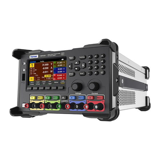
User Manual Introduction HDP43XX/44XX is a programmable DC power supply. It has a user-friendly interface design, excellent performance indicators, a variety of communication interfaces to meet the different needs of users, and a variety of analysis functions to meet the diverse needs of users. -
Page 11: Chapter 1 Quick Start
User Manual Chapter 1 Quick Start Taking the three-channel power supply as an example, this chapter will briefly describe and introduce the front panel, rear panel, user interface, help system, and precautions when using the instrument for the first time. In this way, users can become familiar with this series of power supplies in the shortest possible time. - Page 12 User Manual 1. LCD Display screen 2. Restore default settings 3. Help Used to quickly get relevant help on the use of the instrument. 4. USB Host Used for firmware upgrade or external file saving. 5. Auxiliary function soft keys Operate according to the screen display.
-
Page 13: Rear Panel Introduction
User Manual 3. Rear Panel Introduction 1. Digital IO interface 2. USB interface 3. LAN interface 4. AC selector 5. Power jack 6. Fuse holder 7. Exhaust fan 8. Ground reference point 9. Safety lock 10. GPIB interface 11. RS-232/485 interface... -
Page 14: User Interface
User Manual 4. User Interface 4.1 Main interface 1. Output channel indication When an output channel is selected, the background of the corresponding channel is highlighted. 2. USB device icon display 3. U disk icon display 4. Network icon display 5. -
Page 15: Meter View
User Manual LT: Low temperature protection. The sensor is lower than -10℃, which may be due to environmental problems too low, or the sensor is damaged. So channels are forbidden to output. When the hardware restored to normal, this phenomenon is eliminated. MV: If voltage out of control, it may be the adjustment tube is damaged. -
Page 16: Data Logger View
User Manual 4.3 Data logger view 1. Tracking parameters All parameters of all channels can be tracked and displayed. Press the "Enter" key to turn on or off the tracking display of a single parameter. The display "----" after the parameter indicates that the tracking of the parameter has been turned off. -
Page 17: Help System
User Manual 4.4 Help system The help list can help users quickly understand the instrument. Press "About" to view product information, including product model, serial number, etc. This series of programmable DC power supplies provide help information for any key on the front panel and any menu key. -
Page 18: Chapter 2 Getting Started
User Manual Chapter 2 Getting Started This chapter introduces the items that users need to pay attention to when starting to use this series of programmable DC power supplies in order to carry out subsequent operations smoothly. 1. Check the AC voltage range This series of programmable DC power supplies support various specifications of AC power input, and users can choose the appropriate input gear according to actual needs. -
Page 19: Chapter 3 Function Introduction
User Manual Chapter 3 Function Introduction This chapter will introduce in detail the following functions of this series of programmable DC power supplies: Output voltage and current Over protection Channel delay Output coupling Output inhibit Operation mode ... -
Page 20: Over Protection
User Manual Setting steps: 1. Select the output channel Press the digital channel button on the front panel, or continuously press the left "◁" and right "▷" arrows to select the output channel to be set. 2. Set voltage/current: Press the arrow keys to select voltage or current, use the numeric keyboard or knob to set the value, press "×"... -
Page 21: Output Coupling
User Manual 4. Output coupling Press Source Settings->On/Off Coupling to set the output coupling. After setting the coupling, turn on the output of any one of the channels, and the other coupling channels will be turned on at the same time. If only part of the channel output coupling is set, open the front panel [All On/Off], regardless of whether the channel is set to output coupling, all channels will be turned on. -
Page 22: Operation Mode
User Manual Note: When the output inhibition mode is selected as "Latched", to turn off the output inhibition, you must first switch the "Output Inhibit" to "Live" 6. Operation Mode Press Output Settings->Operation Mode to set the operation mode. For Channel 1 and Channel 2, the operation mode can be set to Independent, Series, Parallel and Tracking. -
Page 23: Tracking
User Manual channel 1, and the output voltage is the set voltage of channel 1. The external wiring method of parallel mode is as follows: 6.4 Tracking In tracking mode, channel 1 and channel 2 are associated with each other, and the voltages track each other. - Page 24 User Manual Steps to set the output list: 1. Select the output channel Press the channel button on the front panel to select the output channel, and press "Output List" to enter the output list setting interface. 2. Create a list ◆Add/remove step Press the "Add"...
- Page 25 User Manual ◆Voltage/Current After List: Set the output value after the list output is completed. Last list value: After the list output is completed, the last list value is output. Return to DC Value: After the list output is completed, the DC value before the list becomes effective is output.
-
Page 26: Data Logger
User Manual Note: The property cannot be set when the list is "Run". The Run/Stop trigger output is valid only when the trigger source is set to Key. When using the list output, you should turn on the channel output first, and then press "Run/Stop", otherwise the complete list cannot be output. - Page 27 User Manual Horizontal: Set the horizontal offset of the displayed waveform. Press "Offset +", "Offset -" to set the offset. The default horizontal time base is 5s/div. 3.Properties property settings ◆Save File Path: Set the file save path. Press the Enter key to enter the file system list, press the up and down arrow keys to browse the files, and press the Select key to select the file path.
-
Page 28: Remote Control
User Manual Delete Char: Delete the previous character. Previous Char: Move the cursor forward one character. Next Char: Move the cursor one character back. ◆Recall: Recall the wave file. An external storage device must be connected to use this function. Press Enter to view the file system list, use the up and down arrow keys to select the file to be recalled. -
Page 29: Lan Remote Control
User Manual 9.2 LAN remote control Connect the back-end network port of the computer to the network port on the rear panel of the power supply with a LAN network cable. Utility→I/O Config→LAN Settings to set the power supply LAN parameters. Press Load menu to load settings, as shown in the figure below: Please configuration of computer IP and other information manually. - Page 30 User Manual After the connection is successful, open the IO software and the device will appear in the LAN list. If the device does not appear, you can manually add the device, enter the device's IP address and protocol, test the VISA address, and click OK to add a new device.
- Page 31 User Manual After a successful connection, the network port icon in the upper right corner of the main interface is displayed as follows: As with USB remote control, after obtaining normal communication, you can use SCPI commands to control the power output. If there is a DHCP server in the LAN, you can open the DHCP function, and the instrument will automatically obtain IP and other information from the DHCP server without manual setup.
-
Page 32: Rs232/485 Remote Control
User Manual Note: If there is no DHCP server on the LAN, you must configure IP and other information manually. 9.3 RS232/485 remote control Each parameter is unchanged by default. Pay attention to the wiring: Pin2 is RS232_TX, Pin3 is RS232_RX, Pin4 is RS485_A, Pin9 is RS485_B. -
Page 33: Gpib Remote Control
User Manual Open the IO software, select to add a device, set the corresponding baud rate, test the VISA address, and click OK to add a new device. As with USB remote control, after obtaining normal communication, you can use SCPI commands to control the power output. -
Page 34: Utilities
User Manual 10. Utilities 10.1 Store/recall Store/Recall can store and recall settings as volatile settings, such as: voltage and current values, OVP, OCP, output coupling, output status, operation mode, list output, trigger settings, data recording, key tone, Help language etc. 10.1.1 Store setting Store Settings: Used to select internal storage or external storage. -
Page 35: I/O Setting
User Manual 10.1.3 Power-on setting Press "Power On Setting" to select a state to be automatically recalled after power-on. You can choose the default settings or user-specified settings. Press "SetPwrOn" to save the settings. Users can also check "□Set this as power-on state." in "Store Settings" to set. 10.1.4 Restore default settings Press "Set to Defaults"... - Page 36 User Manual In: display the state applied to Pin (binary bit 0 or 1). 10.2.3 Trigger output Select Trigger Out, Pin1-Pin3 can be set as trigger output. This function is used in conjunction with the list output (BOST/EOST). The Pin assigned this function will output a pulse signal of about 5ms. Polarity: Set the Pin polarity to positive or negative, that is, the trigger output pulse is positive or negative.
-
Page 37: Setup
User Manual 10.2.5 Coupling off/on Select Couple Off/Couple On, Pin1-Pin3 can be set as coupling off/on. Only one Pin can be set as coupling off or coupling on, and the polarity of Pin is fixed to negative. Changing the input signal corresponding to Pin can control the coupling output of the specified channel. Note: First, set at least two channel couplings to be turned on in the output settings, refer to output coupling chapter. -
Page 38: Lock/Unlock
The following faults may occur during the use of this series of programmable DC power supplies. Users can refer to the following methods to deal with. If the fault still exists, please contact Hantek and provide the equipment information of the instrument (How to obtain: ? ->About). -
Page 39: Chapter 5 Performance Index
(2) Make sure that the USB flash drive is used. This instrument does not support hard drive USB flash drives. (3) After restarting the instrument, insert the U disk to check. (4) If the USB flash drive still cannot be used normally, please contact Hantek. Chapter 5 Performance Index DC output (0℃~40℃) - Page 40 User Manual Voltage <0.01%+2mV Current <0.01%+250μA Line Regulation ±(% of output + offset) Voltage <0.01%+2mV Current <0.01%+250μA Ripple and noise (20Hz to 20MHz) Normal mode <350μVrms /2mVpp voltage Accuracy(25℃±5℃) ±(% of output + offset) Programming Readback Channel Voltage Current Voltage Current 0.05%+10mV 0.2%+5mA 0.05%+10mV...
- Page 41 User Manual GPIB 1 piece (Option) Surroundings Cooling method Air-cooled Operating temperature 0℃~50℃ Storage temperature -40℃~70℃ Humidity 0℃~30℃: ≤95% relative humidity 30℃~40℃: ≤75% relative humidity 40℃~50℃: ≤45% relative humidity Altitude Below 3000 meters...
Need help?
Do you have a question about the HDP43 Series and is the answer not in the manual?
Questions and answers