Table of Contents
Advertisement
Quick Links
Advertisement
Table of Contents

Subscribe to Our Youtube Channel
Related Manuals for SEW 4338 mO


Summary of Contents for SEW 4338 mO
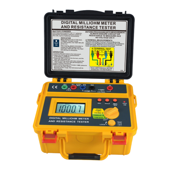
- Page 1 4338 mO DIGITAL MILLIOHM METER AND RESISTANCE TESTER INSTRUCTION MANUAL...
-
Page 2: Table Of Contents
INDEX PAGE 1. INTRODUCTION......2. SAFETY NOTES......3. FEATURES........4. SPECIFICATIONS......5. GENERAL........6. INSTRUMENT LAYOUT....6-10 7. MEASUREMENT......10-12 8. MAINTENANCE......9. FUSE REPLACEMENT.... -
Page 3: Introduction
1. INTRODUCTION NOTE This meter has been designed and tested According to CE Safety Requirements for Electronic Measuring Apparatus, IEC / EN 61010-1 and other safety standards. Follow all warnings to ensure safe operation. WARNING READ "SAFETY NOTES" (NEXT PAGE) BEFORE USING THE METER. -
Page 4: Safety Notes
2. SAFETY NOTES ● Read the following safety information carefully Before attempting to operate or service the meter. ● Use the meter only as specified in this manual. Otherwise, the protection provided by the meter may be impaired. ● Rated environmental conditions : (1) Indoor Use. -
Page 5: Features
3. FEATURES ● Four terminal measurement for mΩ. ● 4-wire method testing(mΩ): 1100.0mΩ / 11000mΩ. ● 2-wire method resistance testing: 110.00Ω / 1.1000kΩ / 11.000kΩ / 110.00kΩ / 1.1000MΩ / 11.000MΩ / 110.0MΩ.(auto ranging) ● Maximum resolution of 0.1mΩ. ● Large LCD (68×34mm). ●... -
Page 6: Specifications
4. SPECIFICATIONS mΩ measurement (4-wire method) Measuring ranges 0~1100.0mΩ in steps of 100uΩ 0~11000mΩ in steps of 1mΩ (mΩ) ±0.8% of reading ±4 digits over the operating temperature range Accuracy 0°C ~ 40°C, with the supplied test leads Auto-ranging Resistance measurement 2-wire method Range Resolution... -
Page 7: General
5. GENERAL ● Protection fuse: 200mA/250V × 1 ● Dimensions : 250(L) × 190(W) ×126(D)mm ● Weight : Approx. 1848g (battey included) ● Power source : 1.5V "C" battery × 8 ● Low Battery Indication : " " sign appears on the display when the battery voltage drops below accurate operating level. -
Page 8: Instrument Layout
6. INSTRUMENT LAYOUT (11) TEST HOLD (10) mΩ (AUTO) 110MΩ 110.00Ω 11000mΩ 1100.0mΩ DIGITAL MILLIOHM METER AND RESISTANCE TESTER TEST LOCK ● Test Leads ● Special Resistance Test Lead (Specialized for 2-wire resistance testing) - Page 9 (1) C1 Termianl (7) TEST Button (2) P1 Termianl (8) TEST ON LED (3) P2 Termianl (9) REL Button (4) C2 Termianl (10) HOLD Button (5) Ω Terminal (11) MAX/MIN Button (6) Function Rotary Switch (1) C1 Termianl This is the C1 terminal which is used for mΩ measurement, for 1100.0mΩ...
- Page 10 (4) C2 Termianl This is the P2 terminal which is used for mΩ measurement, for 1100.0mΩ and 11000mΩ (4-wire testing). This terminal is also the COM terminal for resistance measurement, for 110.00Ω~110MΩ (2-wire testing). (5) Ω Terminal This is the positive input termial for resistance measurement, for 110.00Ω~110MΩ(2-wire testing).
- Page 11 (9) REL Button In REL mode, the LCD displays D , where =1,2,3,..., D is the last value before REL is pushed, and D is the current value. If REL is pushed again in REL mode, the meter displays the reference value. The meter returns to normal operation if REL is pressed and held for longer than one second.
-
Page 12: Measurement
to normal operation if MAX/MIN is pressed and held for longer than one second. Pressing HOLD in MAX/MIN mode makes the meter stop updating the maximum or the minimum value. 7. MEASUREMENT mΩ MEASUREMENT(4-wire method). Use C1, P1, P2, C2 four terminals for 4-wire mΩ... - Page 13 When press the TEST button, the TEST ON LED will glow red. TEST Please remember to release the TEST button after mΩ testing, the TEST ON LED will disappear. TEST It's necessary to release the TEST button after testing. RESISTANCE MEASUREMENT(2-wire method). Use P2, C2, Ω...
- Page 14 2-wire method DC20V Ω 110MΩ 0-110MΩ 110.00Ω Fig 2 Connect the special resistance test lead and the red test lead to the object or device for measuring resistance (110.00Ω/1.1000kΩ/11.000kΩ/110.00kΩ/1. 1000MΩ/11.000MΩ/110.0MΩ auto ranging). Turn the rotary switch to the position of 110.00Ω~110MΩ(yellow area), then get the resistance reading on the LCD.
-
Page 15: Maintenance
8. MAINTENANCE Battery replacement : When low battery warning symbol " "appears, change new batteries as follows : (1) Disconnect the test leads from the instrument and turn off the power. (2) Unscrew the battery cover and replace with new batteries(1.5V "C"... -
Page 16: Fuse Replacement
9. FUSE REPLACEMENT Open the meter case, replace with a new fuse which has the same specification 200mA/250V, 5×20mm. Fuse 200mA / 250V (5 × 20 mm) Due to our policy of constant improvement and development, we reserve the right to change specifications without notice. -14-...
Need help?
Do you have a question about the 4338 mO and is the answer not in the manual?
Questions and answers