Table of Contents
Advertisement
Advertisement
Table of Contents

Related Manuals for Gigabyte GA-Z97P-D3


Summary of Contents for Gigabyte GA-Z97P-D3
- Page 1 GA-Z97P-D3 User's Manual Rev. 1001 12ME-Z97PD3-1001R...
- Page 2 The trademarks mentioned in this manual are legally registered to their respective owners. Disclaimer Information in this manual is protected by copyright laws and is the property of GIGABYTE. No part of this manual may be reproduced, copied, translated, transmitted, or published in any form or by any means without GIGABYTE's prior written permission.
-
Page 3: Table Of Contents
Table of Contents GA-Z97P-D3 Motherboard Layout ...................4 GA-Z97P-D3 Motherboard Block Diagram ..............5 Chapter 1 Hardware Installation ..................6 Installation Precautions ..................6 ..................7 Installing the CPU .................... 9 Installing the Memory ..................10 Installing an Expansion Card ................. 10 Back Panel Connectors .................. 10 Internal Connectors .................. -
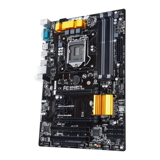
Page 4: Ga-Z97P-D3 Motherboard Layout
GA-Z97P-D3 Motherboard Layout KB_MS CPU_FAN ATX_12V_2X4 HDMI LGA1150 R_USB R_USB30 USB_LAN AUDIO SYS_FAN3 Realtek ® GbE LAN GA-Z97P-D3 B_BIOS PCIEX16 M_BIOS PCIEX1_1 CODEC Intel ® PCIEX1_2 PCIEX4 PCI1 ® Super I/O PCIe to PCI Bridge PCI2 CLR_CMOS F_AUDIO SPDIF_O COMB... -
Page 5: Ga-Z97P-D3 Motherboard Block Diagram
GA-Z97P-D3 Motherboard Block Diagram 1 PCI Express x16 LGA1150 CPU PCIe CLK Dual Channel Memory HDMI PCI Express Bus Dual BIOS 1 PCI Express x4 RJ45 6 SATA 6Gb/s Realtek ® GbE LAN Intel ® 4 USB 3.0/2.0 PCI Express Bus 10 USB 2.0/1.1... -
Page 6: Chapter 1 Hardware Installation
Chapter 1 Hardware Installation Installation Precautions The motherboard contains numerous delicate electronic circuits and components which can become manual and follow these procedures: Prior to installation, make sure the chassis is suitable for the motherboard. warranty sticker provided by your dealer. These stickers are required for warranty validation. Always remove the AC power by unplugging the power cord from the power outlet before installing or removing the motherboard or other hardware components. - Page 7 Support for Intel ® Core ™ i7 processors/Intel ® Core ™ i5 processors/ Intel ® Core ™ i3 processors/Intel ® Pentium ® processors/Intel ® Celeron ® processors in the LGA1150 package L3 cache varies with CPU Chipset Intel ® Z97 Express Chipset Memory 4 x DDR3 DIMM sockets supporting up to 32 GB of system memory * Due to a Windows 32-bit operating system limitation, when more than 4 GB of physical...
- Page 8 Internal 1 x 24-pin ATX main power connector Connectors 1 x 8-pin ATX 12V power connector 1 x CPU fan header 3 x system fan headers 1 x front panel header 1 x front panel audio header 1 x S/PDIF Out header 6 x SATA 6Gb/s connectors 1 x USB 3.0/2.0 header 3 x USB 2.0/1.1 headers...
-
Page 9: Installing The Cpu
Unique Features Support for Smart Switch Support for Xpress Install Bundled Norton ® Software Intel ® Rapid Start Technology Intel ® Smart Connect Technology Intel ® Smart Response Technology Operating Support for Windows 8.1/8/7 System Form Factor ATX Form Factor; 30.5cm x 20cm prior notice. -
Page 10: Installing The Memory
Installing the Memory Read the following guidelines before you begin to install the memory: Make sure that the motherboard supports the memory. It is recommended that memory of the same capacity, brand, speed, and chips be used. Always turn off the computer and unplug the power cord from the power outlet before installing the memory to prevent hardware damage. - Page 11 HDMI Port The HDMI port is HDCP compliant and supports Dolby True HD and DTS HD audio output. You can use this port to connect your HDMI-supported monitor. The maximum supported dependent on the monitor being used. After installing the HDMI device, make sure to set the default sound playback device to HDMI. USB 2.0/1.1 Port USB 3.0/2.0 Port RJ-45 LAN Port...
-
Page 12: Internal Connectors
Internal Connectors ATX_12V_2X4 SPDIF_O F_USB30 CPU_FAN F_USB1/2/3 SYS_FAN1/SYS_FAN2/SYS_FAN3 COMB SATA3 0/1/2/3/4/5 F_PANEL F_AUDIO CLR_CMOS Read the following guidelines before connecting external devices: First make sure your devices are compliant with the connectors you wish to connect. Before installing the devices, be sure to turn off the devices and your computer. Unplug the power cord from the power outlet to prevent damage to the devices. - Page 13 1/2) ATX_12V_2X4/ATX (2x4 12V Power Connector and 2x12 Main Power Connector) With the use of the power connector, the power supply can supply enough stable power to all the components off and all devices are properly installed. The power connector possesses a foolproof design. Connect the power supply cable to the power connector in the correct orientation.
- Page 14 5) SATA3 0/1/2/3/4/5 (SATA 6Gb/s Connectors) The SATA connectors conform to SATA 6Gb/s standard and are compatible with SATA 3Gb/s and SATA 1.5Gb/s standard. Each SATA connector supports a single SATA device. The Intel ® Chipset supports RAID 0, RAID 1, RAID array.
- Page 15 7) F_AUDIO (Front Panel Audio Header) The front panel audio header supports Intel ® your chassis front panel audio module to this header. Make sure the wire assignments of the module connector match the pin assignments of the motherboard header. Incorrect connection between the module connector and the motherboard header will make the device unable to work or even damage it.
- Page 16 10) F_USB1/2/3 (USB 2.0/1.1 Headers) optional USB bracket. For purchasing the optional USB bracket, please contact the local dealer. Pin No. Pin No. USB DY+ USB DX- USB DY- No Pin USB DX+ Prior to installing the USB bracket, be sure to turn off your computer and unplug the power cord from the power outlet to prevent damage to the USB bracket.
-
Page 17: Chapter 2 Bios Setup
To access the BIOS Setup program, press the <Delete> key during the POST when the power is turned on. To upgrade the BIOS, use either the GIGABYTE Q-Flash or @BIOS utility. Q-Flash allows the user to quickly and easily upgrade or back up BIOS without entering the operating system. -
Page 18: Startup Screen
Startup Screen The following startup Logo screen will appear when the computer boots. Function Keys There are three different BIOS modes as follows and you can use the <F2> key to switch between these modes. The quickly and easily. The ST Mode provides a fancy and user-friendly BIOS environment where users can easily point and click through various settings and make adjustments for optimum performance. - Page 19 Whether the system will work stably with the overclock/overvoltage settings you made is dependent on your overall and reduce the useful life of these components. This page is for advanced users only and we recommend you not to M.I.T. Current Status This screen provides information on CPU/memory frequencies/parameters.
- Page 20 CPU PLL Selection Allows you to set the CPU PLL. Auto Filter PLL Level Allows you to set the Filter PLL. Auto Uncore Ratio Allows you to set the CPU Uncore ratio. The adjustable range is dependent on the CPU being used. Uncore Frequency Displays the current CPU Uncore frequency.
- Page 21 CPU Thermal Monitor (Note 1) Enables or disables Intel ® Thermal Monitor function, a CPU overheating protection function. When enabled, the CPU core frequency and voltage will be reduced when the CPU is overheated. Auto lets the BIOS CPU EIST Function (Note 1) Enables or disables Enhanced Intel ®...
- Page 22 Memory Timing Mode Manual and Advanced Manual allows the Channel Interleaving, Rank Interleaving, and memory timing When using a non-XMP memory module or is set to Disabled, the value is set to , the value is displayed according to the SPD data on the XMP memory. Channel Interleaving Enables or disables memory channel interleaving.
- Page 23 CPU Fan Speed Control (CPU_FAN Connector) Allows you to determine whether to enable the fan speed control function and adjust the fan speed. Normal Allows the fan to run at different speeds according to the CPU temperature. You can Silent Allows the fan to run at slow speeds.
-
Page 24: System Information
System Information This section provides information on your motherboard model and BIOS version. You can also select the default language used by the BIOS and manually set the system time. System Language Selects the default language used by the BIOS. System Date value. -
Page 25: Bios Features
A password is required for booting the system and for entering the BIOS Setup program. Full Screen LOGO Show Allows you to determine whether to display the GIGABYTE Logo at system startup. Disabled skips the Fast Boot Enables or disables Fast Boot to shorten the OS boot process. Ultra Fast provides the fastest bootup VGA Support Allows you to select which type of operating system to boot. - Page 26 USB Support Disabled All USB devices are disabled before the OS boot process completes. Full Initial All USB devices are functional in the operating system and during the POST. Fast Boot is set to Enabled. This item is disabled when Fast Boot is set to Ultra Fast.
- Page 27 CSM Support Never Disables UEFI CSM and supports UEFI BIOS boot process only. Windows 8 Features is set to Windows 8. Boot Mode Selection Allows you to select which type of operating system to boot. UEFI and Legacy Allows booting from operating systems that support legacy option ROM or UEFI Legacy Only Allows booting from operating systems that only support legacy Option ROM.
-
Page 28: Peripherals
To cancel the password, press <Enter> on the password item and when requested for the password, enter Peripherals Initial Display Output card or the onboard graphics. XHCI Mode Allows you to determine the operating mode for the xHCI controller in OS. Smart Auto This mode is available only when the BIOS supports the xHCI controller in the pre-boot environment. - Page 29 Disabled The USB 3.0 ports are routed to the EHCI controller and the xHCI controller is turned off. All USB 3.0 devices function as High Speed devices regardless of xHCI software support/availability. Audio Controller If you wish to install a 3rd party add-in audio card instead of using the onboard audio, set this item to Disabled.
- Page 30 Serial ATA Port 0/1/2/3/4/5 Port 0/1/2/3/4/5 Hot plug External SATA parallel port. Serial Port A (Serial Port on the Back Panel) Serial Port B (Onboard COMB Connector) Parallel Port Device Mode Parallel Port is set to Enabled. Selects an operating mode for the Intel(R) Smart Connect Technology ISCT Support Enables or disables Intel...
-
Page 31: Power Management
Power Management Power Loading Enables or disables dummy load. When the power supply is at low load, a self-protection will activate causing it to shutdown or fail. If this occurs, please set to Enabled. Auto Resume by Alarm If enabled, set the date and time as following: Wake up hour/minute/second: Set the time at which the system will be powered on automatically. - Page 32 Power On By Keyboard Allows the system to be turned on by a PS/2 keyboard wake-up event. Note: To use this function, you need an ATX power supply providing at least 1A on the +5VSB lead. Any Key Press any key to turn on the system. Keyboard 98 Press POWER button on the Windows 98 keyboard to turn on the system.
-
Page 33: Save & Exit
Save & Exit Save & Exit Setup Press <Enter> on this item and select Yes. This saves the changes to the CMOS and exits the BIOS Setup program. Select No or press <Esc> to return to the BIOS Setup Main Menu. Exit Without Saving Press <Enter>... -
Page 34: Chapter 3 Appendix
Chapter 3 Appendix Before you begin Windows setup disk. Motherboard driver disk. A USB thumb drive A. Installing SATA hard drive(s) in your computer Attach one end of the SATA signal cable to the rear of the SATA hard drive and the other end to available SATA port on the motherboard. - Page 35 Enter the Intel ® Step: 1. After the POST memory test begins and before the operating system boot begins, look for a message which 2. After you press <Ctrl> + <I>, the MAIN MENU screen will appear. If you want to create a RAID array, select Create RAID Volume in MAIN MENU and press <Enter>.
-
Page 36: Drivers Installation
You can click the Xpress Install button and "Xpress Install" will install all of the selected drivers. Or click the arrow icon to individually install the drivers you need. For more software information, please visit GIGABYTE's website. - 36 -... -
Page 37: Regulatory Statements
Contravention will be prosecuted. We believe that the information contained herein was accurate in all respects at the time of printing. GIGABYTE cannot, however, assume any responsibility for errors or omissions in this text. Also note that the information in this document is subject to change without notice and should not be construed as a commitment by GIGABYTE. - Page 38 FCC Notice (U.S.A. Only) This equipment has been tested and found to comply with the limits for a Class B digital device, pursuant to Part 15 of the FCC Rules. These limits are designed to provide reasonable protection against harmful interference in a residential installation.
- Page 39 - 39 -...
-
Page 40: Contact Us
Address: No.6, Bao Chiang Road, Hsin-Tien Dist., New Taipei City 231,Taiwan TEL: +886-2-8912-4000, FAX: +886-2-8912-4005 You may go to the GIGABYTE website, select your language in the language list on the top right corner of the website. GIGABYTE Global Service System question, please link to: http://ggts.gigabyte.com.tw...
Need help?
Do you have a question about the GA-Z97P-D3 and is the answer not in the manual?
Questions and answers