Table of Contents
Advertisement
Advertisement
Table of Contents
Troubleshooting

Related Manuals for Gigabyte GA-Z97X-Gaming 3


Summary of Contents for Gigabyte GA-Z97X-Gaming 3
- Page 1 GA-Z97X-Gaming 3 User's Manual Rev. 1001 12ME-Z97XGM3-1001R...
-
Page 3: Identifying Motherboard Revision
GIGABYTE's prior written permission. Documentation Classifications In order to assist in the use of this product, GIGABYTE provides the following types of documentations: „ For quick set-up of the product, read the Quick Installation Guide included with the product. -
Page 4: Table Of Contents
Table of Contents Box Contents ........................6 Optional Items .........................6 GA-Z97X-Gaming 3 Motherboard Layout ................7 GA-Z97X-Gaming 3 Motherboard Block Diagram ............8 Chapter 1 Hardware Installation ..................9 Installation Precautions ..................9 1-2 Product Specifications ..................10 Installing the CPU and CPU Cooler ............... 13 1-3-1 Installing the CPU ....................13... - Page 5 Chapter 4 Drivers Installation ..................77 Chipset Drivers ....................77 Application Software ..................78 Information ..................... 78 Chapter 5 Unique Features ...................79 BIOS Update Utilities ..................79 5-1-1 Updating the BIOS with the Q-Flash Utility .............79 5-1-2 Updating the BIOS with the @BIOS Utility .............82 APP Center ....................
-
Page 6: Box Contents
Box Contents 5 GA-Z97X-Gaming 3 motherboard 5 Motherboard driver disk 5 User's Manual 5 Quick Installation Guide 5 Four SATA cables 5 I/O Shield 5 One 2-Way SLI bridge connector The box contents above are for reference only and the actual items shall depend on the product package you obtain. -
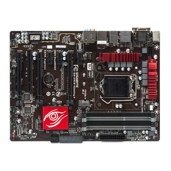
Page 7: Ga-Z97X-Gaming 3 Motherboard Layout
GA-Z97X-Gaming 3 Motherboard Layout KB_MS CPU_FAN ATX_12V_2X4 CPU_OPT LGA1150 R_USB USB30_LAN SYS_FAN1 AUDIO PCIEX1_1 SATA3 GA-Z97X-Gaming 3 Qualcomm ® PCIEX16 Atheros Killer E2201 LAN PCIEX1_2 SATA_EXPRESS Intel ® PCIEX1_3 SATA3 PCIEX8 CODEC ® PCIe to Super I/O PCI Bridge B_BIOS... -
Page 8: Ga-Z97X-Gaming 3 Motherboard Block Diagram
GA-Z97X-Gaming 3 Motherboard Block Diagram CPU CLK+/- (100 MHz) 2 PCI Express x8 DDR3 1600/1333 MHz 1 PCI Express x16 Dual Channel Memory LGA1150 PCIe CLK HDMI (100 MHz) DVI-D Switch D-Sub PCI Express Bus 1 PCI Express x4 SATA Express Switch 2 SATA 6Gb/s 3 PCI Express x1... -
Page 9: Chapter 1 Hardware Installation
Chapter 1 Hardware Installation Installation Precautions The motherboard contains numerous delicate electronic circuits and components which can become damaged as a result of electrostatic discharge (ESD). Prior to installation, carefully read the user's manual and follow these procedures: • Prior to installation, make sure the chassis is suitable for the motherboard. • Prior to installation, do not remove or break motherboard S/N (Serial Number) sticker or warranty sticker provided by your dealer. -
Page 10: Product Specifications
* D ue to a Windows 32-bit operating system limitation, when more than 4 GB of physical memory is installed, the actual memory size displayed will be less than the size of the physical memory installed. Dual channel memory architecture Š Support for DDR3 1600/1333 MHz memory modules Š Support for non-ECC memory modules Š Support for Extreme Memory Profile (XMP) memory modules Š ( Go to GIGABYTE's website for the latest supported memory speeds and memory modules.) Onboard Integrated Graphics Processor: Š Graphics 1 x D-Sub port, supporting a maximum resolution of 1920x1200@60Hz 1 x DVI-D port, supporting a maximum resolution of 1920x1200@60Hz * The DVI-D port does not support D-Sub connection by adapter. 1 x HDMI port, supporting a maximum resolution of 4096x2160@24Hz or 2560x1600@60Hz * S upport for HDMI 1.4a version. - Page 11 Multi-Graphics Support for 3-Way/2-Way AMD CrossFire and 2-Way NVIDIA Technology ™ ® ™ Š Technology Storage Interface Š Chipset: 1 x M.2 PCIe connector 1 x SATA Express connector 6 x SATA 6Gb/s connectors (SATA3 0~5) ( M.2, SATA Express, and SATA3 4/5 connectors can only be used one at a time. The SATA3 4/5 connectors will become unavailable when an M.2 SSD is installed.) Support for RAID 0, RAID 1, RAID 5, and RAID 10 Chipset: Š...
- Page 12 Š System Form Factor ATX Form Factor; 30.5cm x 22.5cm Š * G IGABYTE reserves the right to make any changes to the product specifications and product-related information without prior notice. * P lease visit the Support & Downloads\Utility page on GIGABYTE's website to check the supported operating system(s) for the software listed in the "Unique Features" and "Bundled Software" columns. Hardware Installation - 12 -...
-
Page 13: Installing The Cpu And Cpu Cooler
Read the following guidelines before you begin to install the CPU: • Make sure that the motherboard supports the CPU. (Go to GIGABYTE's website for the latest CPU support list.) • Always turn off the computer and unplug the power cord from the power outlet before installing the CPU to prevent hardware damage. - Page 14 B. Follow the steps below to correctly install the CPU into the motherboard CPU socket. • Before installing the CPU, make sure to turn off the computer and unplug the power cord from the power outlet to prevent damage to the CPU. •...
-
Page 15: Installing The Cpu Cooler
1-3-2 Installing the CPU Cooler Follow the steps below to correctly install the CPU cooler on the motherboard. Male Push Pin Direction of the Arrow Sign The Top on the Male of Female Push Pin Push Pin Female Push Pin Step 1: Step 2: Before installing the cooler, note the direction of the... -
Page 16: Installing The Memory
• Make sure that the motherboard supports the memory. It is recommended that memory of the same capacity, brand, speed, and chips be used. (Go to GIGABYTE's website for the latest supported memory speeds and memory modules.) • Always turn off the computer and unplug the power cord from the power outlet before installing the memory to prevent hardware damage. -
Page 17: Installing A Memory
1-4-2 Installing a Memory Before installing a memory module, make sure to turn off the computer and unplug the power cord from the power outlet to prevent damage to the memory module. DDR3 and DDR2 DIMMs are not compatible to each other or DDR DIMMs. Be sure to install DDR3 DIMMs on this motherboard. Notch DDR3 DIMM A DDR3 memory module has a notch, so it can only fit in one direction. Follow the steps below to correctly install... -
Page 18: Installing An Expansion Card
Installing an Expansion Card Read the following guidelines before you begin to install an expansion card: • Make sure the motherboard supports the expansion card. Carefully read the manual that came with your expansion card. • Always turn off the computer and unplug the power cord from the power outlet before installing an expansion card to prevent hardware damage. -
Page 19: Setting Up Amd Crossfire ™ /Nvidia ® Sli ™ Configuration
Setting up AMD CrossFire /NVIDIA Configuration ™ ® ™ A. System Requirements - Windows 8.1/8/7 operating system - A CrossFire/SLI-supported motherboard with two or more PCI Express x16 slots and correct driver - CrossFire/SLI-ready graphics cards of identical brand and chip and correct driver (Current GPUs that support 3-Way CrossFire technology include the ATI Radeon HD 3800, HD 4800, HD ™... -
Page 20: Back Panel Connectors
Back Panel Connectors PS/2 Keyboard and PS/2 Mouse Port Use the upper port (green) to connect a PS/2 mouse and the lower port (purple) to connect a PS/2 keyboard. D-Sub Port The D-Sub port supports a 15-pin D-Sub connector and supports a maximum resolution of 1920x1200@60Hz (the actual resolutions supported depend on the monitor being used). Connect a monitor that supports D-Sub connection to this port. DVI-D Port (Note) The DVI-D port conforms to the DVI-D specification and supports a maximum resolution of 1920x1200@60Hz (the actual resolutions supported depend on the monitor being used). Connect a monitor that supports DVI-D connection to this port. USB 3.0/2.0 Port The USB 3.0 port supports the USB 3.0 specification and is compatible to the USB 2.0/1.1 specification. Use this port for USB devices such as a USB keyboard/mouse, USB printer, USB flash drive and etc. HDMI Port The HDMI port is HDCP compliant and supports Dolby True HD and DTS HD Master Audio formats. It also supports up to 192KHz/24bit 8-channel LPCM audio output. - Page 21 USB 2.0/1.1 Port The USB port supports the USB 2.0/1.1 specification. Use this port for USB devices such as a USB keyboard/mouse, USB printer, USB flash drive and etc. RJ-45 LAN Port The Gigabit Ethernet LAN port provides Internet connection at up to 1 Gbps data rate. The following describes the states of the LAN port LEDs.
-
Page 22: Internal Connectors
Internal Connectors ATX_12V_2X4 F_AUDIO SPDIF_O CPU_FAN F_USB30 SYS_FAN1/2/3 F_USB1/F_USB2 CPU_OPT COMA SATA_EXPRESS SATA3 0/1/2/3/4/5 CLR_CMOS F_PANEL Read the following guidelines before connecting external devices: • First make sure your devices are compliant with the connectors you wish to connect. • Before installing the devices, be sure to turn off the devices and your computer. Unplug the power cord from the power outlet to prevent damage to the devices. - Page 23 1/2) ATX_12V_2X4/ATX (2x4 12V Power Connector and 2x12 Main Power Connector) With the use of the power connector, the power supply can supply enough stable power to all the components on the motherboard. Before connecting the power connector, first make sure the power supply is turned off and all devices are properly installed. The power connector possesses a foolproof design. Connect the power supply cable to the power connector in the correct orientation.
-
Page 24: Fan Headers
3/4) CPU_FAN/SYS_FAN1/SYS_FAN2/SYS_FAN3 (Fan Headers) All fan headers on this motherboard are 4-pin. Most fan headers possess a foolproof insertion design. When connecting a fan cable, be sure to connect it in the correct orientation (the black connector wire is the ground wire). The motherboard supports CPU fan speed control, which requires the use of a CPU fan with fan speed control design. For optimum heat dissipation, it is recommended that a system fan be installed inside the chassis. -
Page 25: Chapter 2 Bios Setup
1 2 3 6) SATA_EXPRESS (SATA Express Connector) The SATA Express connector supports a single SATA Express device. B S S 7) SATA3 0/1/2/3/4/5 (SATA 6Gb/s Connectors) The SATA connectors conform to SATA 6Gb/s standard and are compatible with SATA 3Gb/s and SATA 1.5Gb/s standard. -
Page 26: Configuring Sata Controllers
Chapter 3 Configuring SATA Hard Drive(s) RAID Levels RAID 0 RAID 1 RAID 5 RAID 10 Minimum Number of Hard ≥2 ≥3 ≥4 Drives Array Capacity Number of hard Size of the smallest (Number of hard (Number of hard drives * Size of the drive drives -1) * Size of drives/2) * Size of the smallest drive the smallest drive smallest drive Fault Tolerance To configure SATA hard drive(s), follow the steps below: A. - Page 27 B. Configuring SATA controller mode in BIOS Setup Make sure to configure the SATA controller mode correctly in system BIOS Setup. Step 1: Turn on your computer and press <Delete> to enter BIOS Setup during the POST (Power-On Self-Test). Go to Peripherals\SATA Configuration, make sure Integrated SATA Controller is enabled. To create RAID, set SATA Mode Selection to RAID (Figure 1). If you do not want to create RAID, set this item to IDE or AHCI. Figure 1 Step 2: If you want to configure UEFI RAID, follow the steps in "C-1." To enter the legacy RAID ROM, save the settings and exit BIOS Setup. Refer to "C-2" for more information. The BIOS Setup menus described in this section may differ from the exact settings for your motherboard.
- Page 28 C-1. UEFI RAID Configuration Only Windows 8.1/8 64-bit supports UEFI RAID configuration. Step 1: In BIOS Setup, go to BIOS Features and set Windows 8 Features to Windows 8 and CSM Support to Never. (Figure 2) Save the changes and exit BIOS Setup. Figure 2 Step 2: After the system reboot, enter BIOS Setup again. Then enter the Peripherals\Intel(R) Rapid Storage Technology sub-menu (Figure 3).
- Page 29 Step 3: On the Intel(R) Rapid Storage Technology menu, press <Enter> on Create RAID Volume to enter the Create RAID Volume screen. Enter a volume name with 1~16 letters (letters cannot be special characters) under the Name item and press <Enter>. Then, select a RAID level (Figure 4). RAID levels supported include RAID 0, RAID 1, RAID 10, and RAID 5 (the selections available depend on the number of the hard drives being installed). Next, use the down arrow key to move to Select Disks. Figure 4 Step 4: Under Select Disks item, select the hard drives to be included in the RAID array. Press the <Space> key on the hard drives to be selected (selected hard drives are marked with "X"). Then set the stripe block size (Figure 5). The stripe block size can be set from 4 KB to 128 KB. Once you have selected the stripe block size, set the volume capacity.
- Page 30 Step 5: After setting the capacity, move to Create Volume and press <Enter> to begin. (Figure 6) Figure 6 After completing, you'll be brought back to the Intel(R) Rapid Storage Technology screen. Under RAID Volumes you can see the new RAID volume. To see more detailed information, press <Enter> on the volume to check for information on RAID level, stripe block size, array name, and array capacity, etc. (Figure 7) Figure 7 - 65 -...
- Page 31 Delete RAID Volume To delete a RAID array, press <Enter> on the volume to be deleted on the Intel(R) Rapid Storage Technology screen. After entering the RAID VOLUME INFO screen, press <Enter> on Delete to enter the Delete screen. Press <Enter> on Yes (Figure 8). Figure 8 Configuring SATA Hard Drive(s) - 66 -...
- Page 32 C-2. Configuring Legacy RAID ROM Enter the Intel legacy RAID BIOS setup utility to configure a RAID array. Skip this step and proceed with the ® installation of Windows operating system for a non-RAID configuration. Step 1: After the POST memory test begins and before the operating system boot begins, look for a message which says "Press <Ctrl-I> to enter Configuration Utility" (Figure 9). Press <Ctrl> + <I> to enter the RAID Configuration Utility. Intel(R) Rapid Storage Technology - Option ROM - 13.0.0.2075 Copyright (C) Intel Corporation. All Rights Reserved. RAID Volumes : None defined.
- Page 33 Step 3: After entering the CREATE VOLUME MENU screen, enter a volume name with 1~16 letters (letters cannot be special characters) under the Name item and press <Enter>. Then, select a RAID level (Figure 11). RAID levels supported include RAID 0, RAID 1, RAID 10, and RAID 5 (the selections available depend on the number of the hard drives being installed). Press <Enter> to proceed. Intel(R) Rapid Storage Technology - Option ROM - 13.0.0.2075 Copyright (C) Intel Corporation. All Rights Reserved. [ CREATE VOLUME MENU ] Name : Volume0 RAID Level : RAID0(Stripe) Disks : Select Disks Strip Size : 16KB...
- Page 34 Step 5: Enter the array capacity and press <Enter>. Finally press <Enter> on the Create Volume item to begin creating the RAID array. When prompted to confirm whether to create this volume, press <Y> to confirm or <N> to cancel (Figure 13). Intel(R) Rapid Storage Technology - Option ROM - 13.0.0.2075 Copyright(C) Intel Corporation. All Rights Reserved. [ CREATE VOLUME MENU ] Name : Volume0 RAID Level : RAID0(Stripe) Disks :...
- Page 35 Recovery Volume Options Intel Rapid Recover Technology provides data protection by allowing users to easily restore data and system ® operation using a designated recovery drive. With the Rapid Recovery Technology, which employs RAID 1 functionality, users can copy the data from the master drive to the recovery drive; if needed, the data on the recovery drive can be restored back to the master drive.
- Page 36 Step 3: Press <Enter> under the Select Disks item. In the SELECT DISKS box, press <Tab> on the hard drive you want to use for the master drive and press <Space> on the hard drive you want to use for the recovery drive. (Make sure the recovery drive has equal or larger capacity than the master drive.) Then press <Enter> to confirm (Figure 17). Intel(R) Rapid Storage Technology - Option ROM - 13.0.0.2075 Copyright (C) Intel Corporation. All Rights Reserved. [ CREATE VOLUME MENU ] Name : Volume0 RAID Level : Recovery...
- Page 37 Delete RAID Volume To delete a RAID array, select Delete RAID Volume in MAIN MENU and press <Enter>. In the DELETE VOLUME MENU section, use the up or down arrow key to select the array to be deleted and press <Delete>. When prompted to confirm your selection (Figure 19), press <Y> to confirm or <N> to abort.
-
Page 38: Installing The Sata Raid/Ahci Driver And Operating System
Installing the SATA RAID/AHCI Driver and Operating System With the correct BIOS settings, you are ready to install the operating system. A. Installing the Operating System As Windows 7 already include Intel SATA RAID/AHCI driver, you do not need to install separate RAID/AHCI ®... - Page 39 B. Rebuilding an Array Rebuilding is the process of restoring data to a hard drive from other drives in the array. Rebuilding applies only to fault-tolerant arrays such as RAID 1, RAID 5 or RAID 10 arrays. The procedures below assume a new drive is added to replace a failed drive to rebuild a RAID 1 array. (Note: The new drive must have equal or greater capacity than the old one.) Turn off your computer and replace the failed hard drive with a new one.
- Page 40 • Performing the Rebuild in the Operating System While in the operating system, make sure the chipset driver has been installed from the motherboard driver disk. Then launch the Intel Rapid Storage Technology utility from the desktop. ® Step 2: Select a new drive to rebuild the RAID and click Rebuild.
- Page 41 • Restoring the Master Drive to a Previous State (for Recovery Volume only) When two hard drives are set to Recovery Volume in Update on Request mode, you can restore the master drive data to the last backup state when needed. For example, in case the master drive detects a virus, you can restore the recovery drive data to the master drive.
-
Page 42: Chapter 4 Drivers Installation
Chapter 4 Drivers Installation • Before installing the drivers, first install the operating system. (The following instructions use Windows 8.1 as the example operating system.) • After installing the operating system, insert the motherboard driver disk into your optical drive. Click on the message "Tap to choose what happens with this disc" on the top-right corner of the screen and select "Run Run.exe." (Or go to My Computer, double-click the optical drive and ex- ecute the Run.exe program.) Chipset Drivers... -
Page 43: Application Software
Information This page provides detailed information on the drivers on the driver disk. The Contact page provides contact information of the GIGABYTE Taiwan headquarter. You can click the URL on this page to link to the GIGA- BYTE website to check more information on the GIGABYTE headquarter or worldwide branch offices. Drivers Installation... -
Page 44: Chapter 5 Unique Features
Chapter 5 Unique Features BIOS Update Utilities GIGABYTE motherboards provide two unique BIOS update tools, Q-Flash and @BIOS . GIGABYTE Q-Flash ™ ™ and @BIOS are easy-to-use and allow you to update the BIOS without the need to enter MS-DOS mode. - Page 45 B. Updating the BIOS In the main menu of Q-Flash, use the keyboard or mouse to select an item to execute. When updating the BIOS, choose the location where the BIOS file is saved. The following procedure assumes that you save the BIOS file to a USB flash drive. Step 1: 1. Insert the USB flash drive containing the BIOS file into the computer. In the main menu of Q-Flash, select Update BIOS From Drive. • The Save BIOS to Drive option allows you to save the current BIOS file. •...
-
Page 46: Save & Exit
Step 4: During the POST, press <Delete> to enter BIOS Setup. Select Load Optimized Defaults on the Save & Exit screen and press <Enter> to load BIOS defaults. System will re-detect all peripheral devices after a BIOS update, so we recommend that you reload BIOS defaults. Select Yes to load BIOS defaults Step 5: Select Save &... -
Page 47: Updating The Bios With The @Bios Utility
BIOS or a system that is unable to start. 3. GIGABYTE product warranty does not cover any BIOS damage or system failure resulting from an inadequate BIOS flashing. B. Using @BIOS 1. Update the BIOS Using the Internet Update Function: Click Update from Server, select the @BIOS server site closest to your location and then download the BIOS file that matches your motherboard model. Follow the on-screen... -
Page 48: App Center
APP Center GIGABYTE App Center gives you easy access to a wealth of GIGABYTE apps that help you get the most from your GIGABYTE motherboard . Using a simple, unified user interface, GIGABYTE App Center allows you (Note) to easily launch all GIGABYTE apps installed on your system, check related updates online, and download the apps, drivers, and BIOS. -
Page 49: Easytune
5-2-1 EasyTune GIGABYTE's EasyTune is a simple and easy-to-use interface that allows users to fine-tune their system settings or do overclock/overvoltage in Windows environment. The EasyTune Interface Tabs Information Description The Smart Quick Boost tab provides you with different levels of CPU frequency to choose to achieve desired system performance. After making changes, be sure to restart your system for these changes to take effect. -
Page 50: System Information Viewer
5-2-2 System Information Viewer GIGABYTE System Information Viewer allows you to monitor and adjust the fan speed in the operating system. You can also display the hardware monitor information on the desktop to view the system status at any time. -
Page 51: Ez Setup
5-2-3 EZ Setup The GIGABYTE EZ Setup utility includes the following 'EZ' setups applications that will offer greatly simplified install and configuration procedures: Disk Mode Switch, EZ Smart Response, EZ Rapid Start, EZ Smart Connect, and XHD. Disk Mode Switch Disk Mode Switch allows you to switch the operating mode for your hard drive even after it's been installed with an operating system. - Page 52 EZ Smart Response A. System Requirements 1. An Intel Chipset-based motherboard supporting this feature ® 2. Intel Core series processor ® 3. Intel SATA controllers set to RAID mode ® 4. Intel Rapid Storage Technology utility installed ® (Note 1) 5. A conventional SATA disk and an SSD (Note 2) 6.
- Page 53 EZ Rapid Start A. System Requirements 1. Intel Rapid Start Technology enabled in BIOS Setup ® 2. An SSD with size larger than the total system memory 3. Windows 7 with SP1/Windows 8/Windows 8.1 4. AHCI/RAID mode supported please note if the SSD has been assigned as a member of a RAID array, it cannot be used to set up and Intel Rapid Start store partition); IDE mode not supported ®...
- Page 54 EZ Smart Connect A. System Requirements 1. Intel Smart Connect Technology enabled in BIOS Setup ® 2. Windows 7 with SP1/Windows 8/Windows 8.1 3. Intel Smart Connect Technology utility installed ® 4. Properly-working network connection 5. Programs added to the White List must be turned on (Note) B.
- Page 55 With GIGABYTE XHD , users can quickly configure a RAID-ready system for RAID 0 or RAID 1 when a (Note 1) new SATA drive is added. All with a simple click of a button, XHD helps to enhance your hard drive read/write performance without the need for complex and time-consuming configurations. A. System Requirements 1. An Intel Chipset motherboard supporting RAID ® 2. Intel SATA controllers set to RAID mode ®...
-
Page 56: Fast Boot
5-2-4 Fast Boot Through the simple GIGABYTE Fast Boot interface, you can enable or change the Fast Boot or Next Boot (Note 1) After AC Power Loss setting right in the operating system. The Fast Boot Interface Using Fast Boot • BIOS Fast Boot: This option is the same as the Fast Boot option in BIOS Setup. -
Page 57: Smart Timelock
5-2-5 Smart TimeLock GIGABYTE Smart TimeLock allows you to effectively manage computer or Internet usage time with simple rules and options. The Smart TimeLock Interface Using Smart TimeLock Click the lock icon on the bottom left corner and enter the password . -
Page 58: Smart Recovery 2
5-2-6 Smart Recovery 2 Smart Recovery 2 allows you to back up a partition as an image file every hour. You can use these images to restore your system or files when needed. The Smart Recovery 2 main menu: Button Description Allows you to select the source and destination Settings partition Backup Now Allows you to perform the backup immediately File Allows you to recover your files from the backup Recovery... image System Allows you to recover your system from the Recovery... - Page 59 Recovering your system with Smart Recovery 2: Steps: 1. Click the System Recovery button on the main menu. 2. Select the location where your backup is saved. 3. Use the time slider to select a time point. 4. Select a partition backup created on the selected time point and click Restore.
-
Page 60: Usb Blocker
5-2-7 USB Blocker GIGABYTE USB Blocker provides you with an easy-to-use interface that allows you to block certain USB device types on your PC. Devices classes that are blocked will be ignored by the operating system. The USB Blocker Interface Using USB Blocker Select the class of USB device that you would like to block or unblocked. -
Page 61: Smart Switch
5-2-8 Smart Switch GIGABYTE Smart Switch provides you with the conventional Windows start menu, allowing you to easily access to the apps that you frequently use. You can also select the default screen displayed after you enter Windows. The Smart Switch Interface... -
Page 62: Game Controller
5-2-9 Game Controller GIGABYTE Game Controller allows you to define your own hotkeys and change the mouse sensitivity, helping you make the most out of your keyboard and mouse in games. The Game Controller Interface Using Game Controller: • Hot Key: Create macro commands and define your own hotkeys to quickly perform the function your want. • Speed: Using the Sniper key you can switch the mouse sensitivity when you are in sniper mode for better sniper accuracy. - Page 63 Unique Features - 98 -...
-
Page 64: Chapter 6 Appendix
Chapter 6 Appendix Qualcomm Atheros Killer Network Manager ® The Killer Network Manager allows you to view your network connection status and Internet bandwidth and to configure your network settings. After installing the LAN driver, you can access the Qualcomm Atheros Killer ®... -
Page 65: Configuring Audio Input And Output
6-2 Configuring Audio Input and Output 6-2-1 Configuring 2/4/5.1/7.1-Channel Audio The motherboard provides five audio jacks on the back panel which support 2/4/5.1/7.1-channel audio. (Note) The picture to the right shows the default audio jack Center/Subwoofer Line In assignments. Speaker Out Front Speaker Out The integrated HD (High Definition) audio provides Rear Speaker Out jack retasking capability that allows the user to change Mic In... - Page 66 Step 2: Connect an audio device to an audio jack. The The current connected device is dialog box appears. Select the device according to the type of device you connect. Then click OK. Step 3: On the Speakers screen, click the Speaker Configuration tab.
-
Page 67: Configuring S/Pdif Out
6-2-2 Configuring S/PDIF Out The S/PDIF Out jack can transmit audio signals to an external decoder for decoding to get the best audio quality. 1. Connecting a S/PDIF Out Cable: Connect a S/PDIF optical cable to an external decoder for transmitting the S/PDIF digital audio signals. Connects to a S/PDIF optical cable 2. -
Page 68: Configuring Microphone Recording
6-2-3 Configuring Microphone Recording Step 1: Switch to Windows desktop mode. The HD Audio Manager icon will appear in the notification area. Double-click the icon to access the HD Audio Manager. Step 2: Connect your microphone to the Mic in jack (pink) on the back panel or the Mic in jack (pink) on the front panel. Then configure the jack for microphone functionality. Note: The microphone functions on the front panel and back panel cannot be used at the same time. - Page 69 Step 5: To open the Sounder Recorder, move the mouse cursor to the bottom left corner of the screen, click the Start icon to switch to the Start screen (or press the Windows button on the keyboard). Click the icon on the bottom left corner of the screen to access the Apps screen.
-
Page 70: Using The Sound Recorder
Step 2: On the Recording tab, right-click on an empty space and select Show Disabled Devices. Step 3: When the Stereo Mix item appears, right-click on this item and select Enable. Then set it as the default device. Step 4: Now you can access the HD Audio Manager to configure Stereo Mix and use Sound Recorder to record the sound. -
Page 71: Creative Software Suite
6-2-5 Creative Software Suite After installing the audio driver, you can find the Creative Software Suite in Apps>Creative. The Creative Software Suite includes the Creative Software AutoUpdate, Alchemy, and Sound Blaster X-Fi MB3. Creative Alchemy Through the Creative Alchemy, you can enable EAX effects for your games to obtain the most realistic gaming experience. - Page 72 SBX PRO STUDIO: SBX PRO STUDIO provides you with audio playback technologies that deliver audio enhancement for your hardware device. It incorporates five features to allow you to elevate the overall audio experience according to your environments. • CRYSTALIZER Makes the music sound as good as the artist originally intended and adds an enhanced level of realism for movies and games.
- Page 73 EAX EFFECTS & EQ: This panel allows you to enable EAX effects and adjust the strength of certain frequencies for your audio signals. ADVANCED SETTING: This page allows you to set the output device to speakers or headphones and set up your speaker/headphone configurations. (Note: Speakers and headphones cannot be used at the same time.
-
Page 74: Troubleshooting
Troubleshooting 6-3-1 Frequently Asked Questions To read more FAQs for your motherboard, please go to the Support & Downloads\FAQ page on GIGABYTE's website. Q: Why is the light of my keyboard/optical mouse still on after the computer shuts down? A: Some motherboards provide a small amount of standby power after the computer shuts down and that's why the light is still... -
Page 75: Troubleshooting Procedure
6-3-2 Troubleshooting Procedure If you encounter any troubles during system startup, follow the troubleshooting procedure below to solve the problem. START Turn off the power. Remove all peripherals, connecting cables, and power cord etc. Make sure the motherboard does not short-circuit with the chassis or Isolate the short circuit. - Page 76 The power supply, CPU or When the computer is turned on, is the CPU cooler running? CPU socket might fail. The problem is verified and solved. The graphics card, expansion slot, or monitor Check if there is display on your monitor. might fail. The problem is verified and solved. Turn off the computer. Plug in the keyboard and mouse and restart the computer.
-
Page 77: Regulatory Statements
This document must not be copied without our written permission, and the contents there of must not be imparted to a third party nor be used for any unauthorized purpose. Contravention will be prosecuted. We believe that the information contained herein was accurate in all respects at the time of printing. GIGABYTE cannot, however, assume any responsibility for errors or omissions in this text. Also note that the information in this document is subject to change without notice and should not be construed as a commitment by GIGABYTE. - Page 78 FCC Notice (U.S.A. Only) This equipment has been tested and found to comply with the limits for a Class B digital device, pursuant to Part 15 of the FCC Rules. These limits are designed to provide reasonable protection against harmful interference in a residential installation.
- Page 79 Appendix - 114 -...
-
Page 80: Contact Us
• Giga-Byte SINGAPORE PTE. LTD. - Singapore TEL: +86-24-83992342 WEB address : http://www.gigabyte.sg FAX: +86-24-83992102 • Thailand • GIGABYTE TECHNOLOGY (INDIA) LIMITED - India WEB address : http://th.giga-byte.com WEB address : http://www.gigabyte.in • Vietnam • Saudi Arabia WEB address : http://www.gigabyte.vn WEB address : http://www.gigabyte.com.sa... - Page 81 • Greece • Kazakhstan WEB address : http://www.gigabyte.com.gr WEB address : http://www.gigabyte.kz • Czech Republic You may go to the GIGABYTE website, select your language WEB address : http://www.gigabyte.cz in the language list on the top right corner of the website. • GIGABYTE Global Service System To submit a technical or non-technical (Sales/Marketing) question, please link to: http://ggts.gigabyte.com.tw...
Need help?
Do you have a question about the GA-Z97X-Gaming 3 and is the answer not in the manual?
Questions and answers