Sign In
Upload
Download
Table of Contents
Contents
Add to my manuals
Delete from my manuals
Share
URL of this page:
HTML Link:
Bookmark this page
Add
Manual will be automatically added to "My Manuals"
Print this page
×
Bookmark added
×
Added to my manuals
Manuals
Brands
Gigabyte Manuals
Motherboard
GA-Z97M-D3H
User manual
Gigabyte GA-Z97M-D3H User Manual
Hide thumbs
1
2
Table Of Contents
3
4
5
6
7
8
9
10
11
12
13
14
15
16
17
18
19
20
21
22
23
24
25
26
27
28
29
30
31
32
33
34
35
36
37
38
39
40
page
of
40
Go
/
40
Contents
Table of Contents
Bookmarks
Table of Contents
Table of Contents
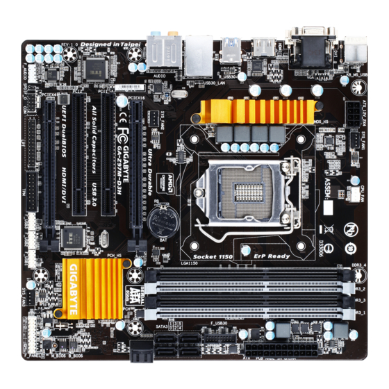
GA-Z97M-D3H/GA-H97M-D3H Motherboard Layout
GA-Z97M-D3H/GA-H97M-D3H Motherboard Block Diagram
Chapter 1 Hardware Installation
Installation Precautions
1-2 Product Specifications
Installing the CPU
Installing the Memory
Installing an Expansion Card
Back Panel Connectors
Internal Connectors
Chapter 2 BIOS Setup
Startup Screen
System Information
2-4 Bios Features
Peripherals
Power Management
Save & Exit
Chapter 3 Appendix
Configuring SATA Hard Drive(S)
Drivers Installation
Regulatory Statements
Contact Us
Advertisement
Quick Links
1
Ga-Z97M-D3H/Ga-H97M-D3H Motherboard Block Diagram
2
1-2 Product Specifications
3
Installing the Memory
4
Internal Connectors
5
2-4 Bios Features
Download this manual
GA-Z97M-D3H
GA-H97M-D3H
User's Manual
Rev. 1001
12ME-Z97MD3H-1001R
GA-Z97M-D3H
GA-H97M-D3H
Table of
Contents
Previous
Page
Next
Page
1
2
3
4
5
Advertisement
Table of Contents
Need help?
Do you have a question about the GA-Z97M-D3H and is the answer not in the manual?
Ask a question
Questions and answers
Related Manuals for Gigabyte GA-Z97M-D3H
Motherboard Gigabyte GA-Z97M-DS3H User Manual
Ga-z97m-ds3h (40 pages)
Motherboard Gigabyte GA-Z97X-Gaming 5 User Manual
(120 pages)
Motherboard Gigabyte GA-Z97M-D3HP User Manual
(44 pages)
Motherboard Gigabyte GA-Z97N-WIFI User Manual
Ga-z97n-wifi; ga-h97n-wifi (80 pages)
Motherboard Gigabyte GA-Z97-D3H User Manual
Ga-z97-d3h; ga-h97-d3h (80 pages)
Motherboard Gigabyte GA-Z97X-SLI User Manual
(80 pages)
Motherboard Gigabyte GA-Z97-HD3 User Manual
(40 pages)
Motherboard Gigabyte GA-Z97X-Gaming G1 User Manual
(136 pages)
Motherboard Gigabyte GA-Z97X-UD3H-BK User Manual
Gigabyte ga-z97x-ud3h-bk motherboard (112 pages)
Motherboard Gigabyte GA-Z97X-Game Plus User Manual
(44 pages)
Motherboard Gigabyte GA-Z97X-UD5H-BK User Manual
(128 pages)
Motherboard Gigabyte GA-Z97X-Gaming 3 User Manual
(81 pages)
Motherboard Gigabyte GA-Z97X-Gaming GT User Manual
(132 pages)
Motherboard Gigabyte GA-Z97N-Gaming 5 User Manual
(80 pages)
Motherboard Gigabyte GA-Z97P-D3 User Manual
(40 pages)
Motherboard Gigabyte GA-Z97-HD3P User Manual
(40 pages)
This manual is also suitable for:
Ga-h97m-d3h
Table of Contents
Print
Rename the bookmark
Delete bookmark?
Delete from my manuals?
Login
Sign In
OR
Sign in with Facebook
Sign in with Google
Upload manual
Upload from disk
Upload from URL


Need help?
Do you have a question about the GA-Z97M-D3H and is the answer not in the manual?
Questions and answers