Optika Italy B-1000 Series Instruction Manual
Hide thumbs
Also See for B-1000 Series:
- Instruction manual (228 pages) ,
- Instruction manual (222 pages) ,
- Instruction manual (264 pages)
Advertisement
Available languages
Available languages
Quick Links
Advertisement

Related Manuals for Optika Italy B-1000 Series


Summary of Contents for Optika Italy B-1000 Series
- Page 1 B-1000 Series INSTRUCTION MANUAL Model B-1000FL-LED Ver. 2.0 2019...
- Page 2 Table of Contents Warning Symbols and conventions Safety Information Intended use List of accessories and spare parts Overview Unpacking Assembling Using the microscope Maintenance Troubleshooting Equipment disposal Page 2...
- Page 3 Warning This microscope is a scientific precision instrument designed to last for many years with a minimum of mainte- nance. It is built to high optical and mechanical standards and to withstand daily use. We remind you that this manual contains important information on safety and maintenance, and that it must therefore be made acces- sible to the instrument users.
- Page 4 List of accessories and spare parts CAT. NO. DESCRIPTION M-005 Micrometric slide, 26x76mm, range 1mm, div. 0,01mm M-613 Polarizing set (filters only). M-615 Lambda filter for polarizing set. M-617.1N Phase contrast set with IOS PLAN objective 40x. M-690 Eyecup (pair). M-619 Photo tube adapter for full frame SLR camera.
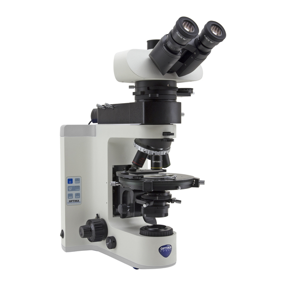
- Page 5 Overview DIOPTRIC EYEPIECE ADJUSTMENT RING PHOTO PORT LED FLUORESCENCE FILTER SELECTOR LEVER NOSEPIECE OBJECTIVE STAGE COARSE FOCUSING KNOB CONDENSER CENTERING KNOBS APERTURE MAIN ON/OFF DIAPHRAGM FIELD DIAPHRAGM FINE FOCUSING KNOB FOCUS-STOP KNOB BRIGHTNESS ADJUSTMENT KNOB Page 5...
- Page 6 Unpacking The microscope is housed in a moulded Styrofoam container. Remove the tape from the edge of the container and lift the top half of the container. Take some care to avoid that the optical items (objectives and eyepieces) fall out and get damaged. Using both hands (one around the arm and one around the base), lift the microscope from the container and put it on a stable desk.
- Page 7 Insert the optical head above the attachment, using the 2mm Allen wrench to tighten the screw. (Fig.2) Fig.2 Insert both eyepieces into the tubes of the optical head. (Fig.3) Fig.3 Insert the condenser under the stage: position until it is well inserted into its holder (under the condenser there is a pin that must fully enter the...
- Page 8 Screw each objective into the thread of the nosepiece, in order of magnification. (Fig.6) Fig.6 Insert the power supply jack on the connector at the rear: one for brightfield illumination, one for illumination. (Fig.7) Fig.7 Page 8...
- Page 9 Using the microscope Control keyboard 1) ON-OFF B-1000 illumination can be managed through 2) BOOST the keyboard placed on the left of the stand: 1) ON-OFF: press this button to turn on or off 3) AUTO-OFF the LED illuminator. 2) BOOST: press this button in order to incre- ase the brightness (useful for high-magnifica- tion objectives or very opaque specimens).
- Page 10 Adjust interpupillary distance Hold the right and left parts of the observation head using both hands and adjust the interpupillary distance by turning the two parts until one circle of light can be seen. (Fig.11) Fig.11 Place the specimen on the stage Fix the specimen slide on the mechanical stage using the...
- Page 11 Diopter adjustment Adjust the fine focusing knob to get the image sharp and clear while observing with your right eye, then turn the left diopter ring to a sharp and clear image also with the other eye. The highpoint eye- pieces allow the user to wear glasses.
- Page 12 Insert the plug of the power supply (on the rear). Adjust the optical head and focus on your sample using the brightfield illumination, as described above. Switch off the brightfield transmitted illumina- Fig.18 tion and place the black slide under the stage (Fig.18) Move the filter selector lever ①...
- Page 13 Maintenance Microscopy environment This microscope is recommended to be used in a clean, dry and shock free environment with a temperature of 5°-40°C and a maximum relative humidity of 75 % (non condensing). Use a dehumidifier if needed. To think about when and after using the microscope •...
- Page 14 Troubleshooting Review the information in the table below to troubleshoot operating problems. PROBLEM CAUSE SOLUTION 1. Optical System LED does not light. Power cord is unplugged. Plug power cord into the power outlet. LED operates, but field of view Aperture and field iris diaphragms are Adjust them to proper sizes.
- Page 15 PROBLEM CAUSE SOLUTION One side of image is blurred. Objective is not correctly engaged in light Make sure that revolving nosepiece path. clicks into place correctly. Revolving nosepiece is not correctly Push slide dovetail all the way until it mounted. is stopped.
- Page 16 Equipment disposal Art.13 Dlsg 25 july 2005 N°151. “According to directives 2002/95/EC, 2002/96/EC and 2003/108/EC relating to the reduction in the use of hazardous substances in electrical and electronic equipment and waste disposal.” The basket symbol on equipment or on its box indicates that the product at the end of its useful life should be collected separately from other waste.
- Page 19 Serie B-1000 MANUALE D’ISTRUZIONI Modello B-1000FL-LED Ver. 2.0 2019...
- Page 20 Sommario Avvertenze Simboli e convenzioni Informazioni di sicurezza Uso previsto Lista accessori e ricambi Panoramica Disimballaggio Assemblaggio Uso del microscopio Manutenzione Risoluzione problemi Misure ecologiche Pagina 20...
- Page 21 Avvertenze Il presente microscopio è uno strumento scientifico di precisione studiato per durare molti anni con una ma- nutenzione minima, essendo costruito secondo i migliori standard ottici e meccanici e progettato per un utilizzo quotidiano. Vi ricordiamo che il presente manuale contiene informazioni importanti sulla sicurezza e manutenzione dello strumento, e deve quindi essere accessibile a chiunque lo utilizzi.
- Page 22 Lista accessori e ricambi COD. DESCRIZIONE M-005 Vetrino micrometrico 26x76 mm. Range 1 mm, div. 0,01 mm M-613 Set per luce polarizzata (solo filtri) M-615 Filtro Lambda per luce polarizzata M-617.1N Set per contrasto di fase, Obiettivo PLAN IOS 40x M-690 Paraocchi (coppia) M-619...
- Page 23 Panoramica OCULARE ANELLO REGOLAZIONE DIOTTRICA USCITA FOTO/VIDEO LEVA DI FLUORESCENZA LED SELEZIONE FILTRI REVOLVER OBIETTIVO MANOPOLA DI MESSA A TAVOLINO FUOCO MACROMETRICA MANOPOLE CENTRAGGIO CONDENSATORE PULSANTE DIAFRAMMA DI ON/OFF APERTURA DIAFRAMMA DI CAMPO MANOPOLA MESSA A FUOCO MICROMETRICA MANOPOLA BLOCCO MESSA A FUOCO MANOPOLA REGOLAZIONE LUMINOSITA’...
- Page 24 Disimballaggio Il microscopio è riposto in un imballo di polistirolo espanso. Rimuovere il nastro adesivo dal collo ed aprire la parte superiore dell’imballo. Fare attenzione a non far cadere le parti ottiche (obiettivi e oculari) nell’estrarre il microscopio dalla scatola per evitare che vengano danneggiati. Utilizzare entrambe le mani (una intorno allo stativo e una alla base), sfilare il microscopio dal contenitore e appoggiarlo su un piano stabile.
- Page 25 Inserire la testata ottica al di sopra del dispositivo per fluo- rescenza, usando la chiave a brugola da 2mm per stringere le viti. (Fig.2) Fig.2 Inserire entrambi gli oculari nei tubi portaoculari della testata ottica. (Fig.3) Fig.3 Inserire il condensatore sotto il tavolino: controllare che sia correttamente inserito nel suo alloggiamento (sotto...
- Page 26 Avvitare ciascun obiettivo nel foro filettato del revolver, in or- dine di ingrandimento. (Fig.6) Fig.6 Inserite le spine dei cavi di alimentazione alle prese sul retro dello stativo: una per l’illuminazione in campo chia- ro, una per l’illuminazione in fluorescenza (Fig.7) Fig.7 Pagina 26...
- Page 27 Utilizzo del microscopio Tastiera di controllo 1) ON-OFF L’illuminazione del B-1000 può essere con- 2) BOOST trollata tramite tastiera posizionata sul lato sinistro dello stativo: 1) ON-OFF: premere questo pulsante per 3) AUTO-OFF accendere/spegnere l’illuminatore LED. 2) BOOST: premere questo pulsante per incrementare la luminosità...
- Page 28 Regolazione distanza interpupillare Tenere la parte destra e sini- stra della testata d’osservazio- ne usando entrambe le mani e regolare la distanza interpupil- lare ruotando le due parti fino ad ottenere la visione di un unico cerchio di luce. (Fig.11) Fig.11 Posizionamento del preparato sul tavolino...
- Page 29 Regolazione diottrica Regolare la micrometrica fino a ottenere un’immagine chiara e nitida osservando col vostro occhio destro, poi ruotare l’anello di regolazione diottrica sull’oculare sinistro fino ad ottenere la visione chiara e nitida anche con l’altro occhio. Gli oculari highpoint permet- tono l’uso anche da parte dei portatori di occhiali.
- Page 30 FLUORESCENZA LED Inserire nella presa il cavo di alimentazione (sul retro dello stativo) Regolare la testata ottica e la messa a fuoco sul vostro campione utilizzando l’illuminazione in campo chiaro, come descritto. Spegnere l’illuminazione trasmessa in cam- Fig.18 po chiaro e posizionare la slitta nera sotto il tavolino (Fig.18) Posizionare la leva di selezione filtro (1) nella posizione desiderata:...
- Page 31 Manutenzione Condizioni ambientali Si raccomanda di utilizzare il microscopio in un ambiente pulito, asciutto e privo di shock elettrici e con una temperatura ambiente tra 5°-40°C ed una umidità relativa massima di 75 % (in assenza di condensa). Utilizzare deumidificatore ove necessario. Da ricordare durante e dopo l’utilizzo del microscopio •...
- Page 32 Risoluzione problemi Seguire le indicazioni della tabella sottostante per risoluzione problemi operativi. PROBLEMA CAUSA SOLUZIONE 1. Sistema ottico LED non funzionante. Il cavo di alimentazione è scollegato. Collegare il cavo di alimentazione alla presa di rete. LED funzionante, ma il campo I diaframmi di campo e di apertura non Regolare l’apertura dei diaframmi.
- Page 33 PROBLEMA CAUSA SOLUZIONE Un lato dell’immagine è L’obiettivo non è perfettamente allineato Assicurarsi che il revolver portaobiettivi sia sfocata. nel percorso ottico. agganciato. Il revolver non è correttamente montato. Inserire la coda di rondine fino a fine corsa. Il tavolino non è correttamente montato. Riposizionarlo.
- Page 34 Pagina 34...
- Page 37 Serie B-1000 MANUAL DEL USUARIO Modelo B-1000FL-LED Ver. 2.0 2019...
- Page 38 Indice Advertencia Símbolos Información de seguridad Utilización Contenido Vista en general Desembalaje Montaje Trabajar con el microscopio Mantenimiento Problemas y soluciones Eliminación de residuos Página 38...
- Page 39 Advertencia Este microscopio es un instrumento científico de precisión diseñado para durar muchos años con un mínimo mantenimiento. Construido siguiéndo los estándares ópticos y mecánicos de alta calidad y para soportar su uso diario. Le recordamos leer este manual el cual contiene información importante sobre seguridad y man- tenimiento, y debe ser accesible a los usuarios de los instrumentos.
- Page 40 Contenido CÓDIGO DESCRIPTION M-005 Preparación micrométrica, 26x76mm, rango 1mm, div. 0,01mm M-613 Juego de polarización (solo filtros) M-615 Filtro Lambda para juego de polarización M-617.1N Juego de contraste de fases, objetivo PLAN IOS 40x M-690 Protectores de goma para oculares (par) M-619 Adaptador de tubo de fotografía para cámaras SLR “full frame”...
- Page 41 Vista general OCULAR ANILLO DE AJUSTE DIÓPTRICO TUBO TRINOCULAR DISCO DE FLUORESCENCIA LENTE DE BERTRAND REVOLVER OBJETIVO MANDO DE ENFOQUE PLATINA MACRO Y MICROMÉTRICO MANDOS PARA CENTRAR EL BOTON DE CONDENSADOR ENCENDIDO/ APAGADO APERTURA DIAFRAGMA DIAFRAGMA DE CAMPO MANDO ENFOQUE MICROMÉTRICO MANDO DE PARADA DE ENFOQUE...
- Page 42 Disimballaggio El microscopio está guardado en una caja de porexpan. Retirar la cinta adhesiva alrededor de la caja y levan- tar la tapa superior. Tener cuidado al levantar la tapa ya que algunos accesorios ópticos (objetivos y oculares) podrían caerse y dañarse. Con las dos manos (una alrededor del estativo y otra debajo la base), levantar el microscopio y ponerlo sobre una mesa estable.
- Page 43 Insertar el cabezal sobre el módulo de epi-fluorescencia, utilizar la llave allen de 2mm para enroscar el tornillo y sujetar el cabezal de modo que quede firme (Fig.2). Fig.2 Insertar ambos oculares en los tubos porta ocular del cabezal (Fig.3). Fig.3 Colocar el condensador bajo la platina: insertar en dicha...
- Page 44 Colocar cada objetivo en el revolver por orden de menor a mayor aumento (Fig.6). Fig.6 Insertar el cable de corriente a la parte trasera del micro- scopio, uno sirve para la iluminación de campo claro y el otro para el módulo de epi- fluorescencia (Fig.7).
- Page 45 Uso del microscopio Control a través de los botones 1) ON-OFF La iluminación en el modelo B-1000 se puede 2) BOOST ajustar mediante los botones ubicado a la izquierda del estativo: 1) ON-OFF: presionar éste boton para en- 3) AUTO-OFF cender o apagar la luz LED.
- Page 46 Ajustar la distancia interpupilar Sujetar con ambas manos los tubos porta oculares y mover hacia arriba o hacia abajo hasta conseguir ver una sola imagen circular. (Fig.11) Fig.11 Colocar la muestra sobre la platina Fijar la muestra con la pinza del carro mecánico de la pla- tina porta preparados.
- Page 47 Ajuste dióptrico Para conseguir una imagen más clara y concisa, gire el mando de enfoque mi- crométrico. Observando con el ojo derecho primero puede girar el anillo de ajuste de dioptrías que hay en el tubo porta-ocular. Haga el mismo proceso observando con el ojo izquierdo.(Fig.15) NOTE: Para una óptima...
- Page 48 FLUORESCENCIA A LED Insertar el cable del transformador (en la parte de atrás). Ajustar el cabezal y enfocar utilizando una de sus preparaciones en iluminación con campo claro tal y como se ha descrito anteriormente. Apagar la iluminación transmitida (campo Fig.18 claro) y colocar la corredera negra debajo de la platina (Fig.
- Page 49 Mantenimiento Recomendaciones de uso del microscopio Se aconseja utilizar éste microscopio en un ambiente limpio y seco. La temperatura recomendada de trabajo es de 5-40º C y la humedad relativa máxima es de 75% (sin conden- sación). Si es necesario utilizar un deshumidificador. A tener en cuenta durante la utilización del microscopio y después de ser utilizado •...
- Page 50 Problemas y soluciones Revisar la tabla inferior para encontrar soluciones a posibles problemas con el microscopio. PROBLEMA CAUSA SOLUCIÓN 1. Sistema óptico No se enciende el LED No está conectado el cable de cor- ri- Conectar el cable de corriente ente El LED funciona pero la Los diafragmas de apertura iris y de...
- Page 51 PROBLEMA CAUSA SOLUCIÓN Un lado de la imagen es bo- El objetivo no está correctamente en el Asegurarse de que el revólver encaje cor- rroso centro del eje de iluminación rectamente El revólver portaobjetivos no está correc- Comprobar que el revolver esta insertado tamente montado totalmente en lugar correcto La platina no está...
- Page 52 Página 52...
- Page 55 Serie B-1000 MANUEL D’INSTRUCTIONS Modèle B-1000FL-LED Ver. 2.0 2019...
- Page 56 Avertissement Symboles Précautions de securité Emploi prévu Liste des accessoires et pièces de rechange Vue d’ensemble Déballage Installation du microscope Utilisation du microscope Entretien Résolution de problèmes Ramassage Page 56...
- Page 57 Avertissement Le présent microscope est un appareil scientifique de précision d’une durée de vie de plusieurs années et un entretien minimum. Les meilleurs composants optiques et mécaniques ont été utilisés pour sa conception ce qui fond de cet instrument un appareil idéal pour une utilisation journalière. Ce guide contient des informations importantes sur la sécurité...
- Page 58 Liste des accessoires et pièces de rechange RÉF. DESCRIPTION M-005 Lame micrométrique, 26x76mm, rang 1mm, div. 0,01mm M-613 Kit de polarisation (seulement les filtres) M-615 Filtre Lambda pour kit de polarisation M-617.1N Kit pour contraste de phase avec objectif IOS PLAN 40x M-690 Oeilletons (la paire) M-619...
- Page 59 Vue d’ensemble OCULAIRE ANNEAU DE RÉGLAGE DIOPTRIQUE PORT PHOTO/VIDÉO ILLUMINATEUR LEVIER DE FLUORESCENCE À SÉLECTION DE FILTRES REVOLVER OBJECTIF MISE AU POINT MACROMÉTRIQUE PLATINE COMMANDES DE CENTRAGE CONDENSEUR INTERRUPTEUR DIAPHRAGME PRINCIPAL ON/OFF D’OUVERTUR DIAPHRAGME DE CHAMP MISE AU POINT MICROMÉTRIQUE BLOCAGE DE LA MISE AU POINT REGLAGE DE L’ÉCLAIRAGE...
- Page 60 Déballage Le microscope est livré dans un emballage en polystyrène. Après avoir ouvert l’emballage, enlever la partie supérieure de la boîte. Operer attentivement afin d’éviter d’endommager les composants optiques (objectifs et oculaires) et afin d’éviter que l’instrument tombe. Enlever le microscope de son emballage avec les deux mains (avec une main soutenez le bras et avec l’autre la base) puis l’appuyer sur une superficie stable et platte.
- Page 61 Insérez la tête optique dessus de l’attachement de , en utili- sant la clé Allen de 2 mm pour serrer la vis. (Fig.2) Fig.2 Insérer les deux oculaires dans les tubes de la tête opti- que. (Fig.3) Fig.3 IInsérer le condenseur sous la platine: veiller à...
- Page 62 Visser chaque objectif dans le filetage de la tourelle, par or- dre de grossissement. (Fig.6) Fig.6 Insérez la prise d’alimentation sur le connecteur à l’arrière: un pour l’éclairage de fond clair, un pour l’éclairage de . (Fig.7) Fig.7 Page 62...
- Page 63 Utilisation du microscope Clavier de contrôle 1) ON-OFF L’éclairage du B-1000 peut être gérée par le 2) BOOST clavier placé sur la gauche du statif: 1) ON-OFF: appuyer sur ce bouton pour allu- mer ou éteindre l’illuminateur LED. 3) AUTO-OFF 2) BOOST: appuyer sur ce bouton pour au- gmenter la luminosité...
- Page 64 Réglage de la distance interpupillaire Tener les parties droite et gau- che de la tête d’observation avec les deux mains et ajuster la distance interpupillaire en tournant les deux parties jusqu’à l’obtention d’un cercle de lumière. (Fig.11) Fig.11 Placer l’échantillon sur la platine Fixer l’...
- Page 65 Réglage dioptrique Régler la commande de mise au point micrométrique pour obtenir une image nette et claire en observant avec votre oeil droit, puis tourner la bague dioptrique de gauche jusqu’à obtenir une image nette et claire également avec l’autre oeil. Les oculaires hi- ghpoint permettent à...
- Page 66 Insérez la prise de l’alimentation (à l’arrière). Ajuster la tête optique et mettre au point votre échantillon en utilisant l’éclairage fond clair, comme décrit ci-dessus. Eteigner l’éclairage transmise fond clair et placer la lame noire sous la platine (Fig.18) Fig.18 Déplacez le levier sélecteur de filtre (1) dans la position souhaitée: B (excitation bleu) ou G (excitation vert)
- Page 67 Réparation et entretien Environnement de travail Il est conseillé d’utiliser le microscope dans un environnement propre et sec, protégé des impactes, à une tem- pérature comprise entre 5°C y 40°C et avec une humidité relative maximale de 75% (en absence de condensa- tion).
- Page 68 Résolution des problèmes Reportez-vous à l’information dans le tableau ci-dessous pour résoudre les problèmes opérationnels. PROBLEME CAUSE SOLUTION 1. Système optique La LED ne s’allume pas. Le cordon d’alimentation est débran- Branchez le cordon d’alimentation dans la ché. prise d’alimentation. La LED est allumée, mais le Les diaphragmes d’ouverture et de Régler aux bonnes dimensions.
- Page 69 PROBLEME CAUSE SOLUTION Une partie de l’image est L’objectif est mal engagé dans le trajet La tourelle porte-objectifs doit être enclen- floue. optique. chée jusqu’au clic. La tourelle porte-objectifs n’est pas bien Appuyer fermement sur l’encoche en montée. forme d’aronde jusqu’à la butée. La platine est mal montée.
- Page 70 Ramassage Conformément à l’Article 13 du D.L du 25 Juillet 2005 nº151 Action des Directives 2002/95/CE, 2002/96/CE et 2003/108/CE, relatives à la réduction de l’utilisation de substances dangereuses dans l’appareil électrique et électronique et à l’élimination des résidus. Le Symbole du conteneur qui figure sur l’appareil électrique ou sur son emballage indique que le produit devra être, à...
- Page 73 B-1000 Series BEDIENUNGSANLEITUNG Modell B-1000FL-LED Ver. 2.0 2019...
-
Page 74: Table Of Contents
Inhalt Hinweis Wartung- und Gefahrzeichen Vorsichtsmaßnahmen Verwendung Inhalt Beschreibung Auspacken Montage Verwendung des Mikroskops Wartung Probleme und Lösungen Wiederverwertung Pagina 74... -
Page 75: Wartung- Und Gefahrzeichen
Hinweis Dieses Mikroskop ist ein wissenschaftliches Präzisionsgerät, es wurde für eine jahrelange Verwendung bei einer minimalen Wartung entwickelt. Dieses Gerät wurde nach den höchsten optischen und mechanischen Standards und zum täglichen Gebrauch hergestellt. Diese Bedienungsanleitung enthält wichtige Informationen zur kor- rekten und sicheren Benutzung des Geräts. - Page 76 Inhalt CODE BESCHREIBUNG M-005 26x76 mm mikrometrischer Objektträger. Range 1 mm, Teilung 0,01 mm M-613 Polarisationssatz (nur Filter) M-615 Lambda Filter für Polarisationssatz M-617.1N Phasenkontrastsatz mit IOS PLAN 40x Objektiv M-690 Augenmuscheln (Paar) M-619 Foto-Adapter für Reflex mit Full Frame Sensor M-173 Foto-Adapter für Reflex mit APS-C Sensor M-620...
-
Page 77: Beschreibung
Beschreibung OKULAR DIOPTRIENVERSTELLUNGSRING USCITA FOTO/VIDEO HALTERUNG FÜR BERTRAND-LIN- FILTERPLATTE SE SCHEIBE REVOLVER OBJEKTIV GROBTRIEBDREHKNOPF DREHTISCH KONDENSOR-ZENTRIE- RUNGSKNÖPFE ON/OFF SCHALTER APERTURBLENDE FELDBLENDE FEINTRIEBDREHKNOPF SCHARFSTELLUNGSFESTHALTUNG LICHTEINSTELLUNG Pagina 77... -
Page 78: Auspacken
Auspacken Das Mikroskop ist in einer Schachtel aus Styroporschicht enthalten. Entfernen Sie das Klebeband von der Schachtel und öffnen Sie mit Vorsicht den oberen Teil, ohne Objektive und Okulare zu beschädigen. Mit beiden Händen (eine um dem Stativ und eine um der Basis) ziehen Sie das Mikroskop aus der Schachtel heraus und stellen Sie es auf eine stabile Oberfläche. - Page 79 Setzen Sie den optischen Kopf auf das Modul der Bertrand- Linse an. Mit dem 3 mm Imbusschlüssel befesti- gen Sie den Kopf. (Abbildung Fig.2 Führen Sie beide Okulare in die Röhrenöffnungen ein. (Abbildung 3) Fig.3 Setzen Sie den Kondensor unter den Kreuztisch ein, so dass er sich in seiner Hal- terung befindet (unter dem Kondensor gibt es einen Bol-...
- Page 80 Schrauben Sie jedes Objektiv nach Vergrößerung (von der kleinsten bis der grössten Ver- größerung) in den Revolver ein. (Abbildung 6) Fig.6 Setzen Sie die Netzteilbu- chse an die Rückseite des Mikroskops ein: eine für die Hellfeld-Beleuchtung, eine für die Fluoreszenz-Beleuchtung. (Abbildung 7) Fig.7 Pagina 80...
-
Page 81: Verwendung Des Mikroskops
Verwendung des Mikroskops Steuerungstastatur 1) ON-OFF Die Beleuchtung des B-1000 kann durch die 2) BOOST Tastatur an der linken Seite des Stativs einge- stellt werden: 1) ON-OFF: drücken Sie diese Taste, um die 3) AUTO-OFF LED Beleuchtung an- und auszuschalten. 2) BOOST: drücken Sie diesen Knopf, um die Beleuchtung zu erhöhen (nützlich bei Objekti- ve mit grosser Vergrößerung oder bei sehr... - Page 82 Einstellung des Augenabstandes Man muss den Augenabstand der Okulare einstellen, bis ein einzelnes rundes Hellfeld ge- funden wird, dabei werden die linken und rechten Seiten des Kopfes mit beiden Händen stillgehalten (Abbildung 11) Fig.11 Objektträger auf den Tisch legen Befestigen Sie den Objektträger auf den Kreuztisch mit Hilfe der dafür vorgesehenen Klemmen.
- Page 83 Dioptrienverstellung Stellen Sie den Feintriebknopf ein, bis ein scharfes klares Bild durch Betrachtung mit dem rechten Auge zu sehen ist. Wiederholen Sie dieses Verfahren mit dem linken Dioptrienverstellungsring und dem linken Auge (Abbildung HINWEIS: Wenn Sie Brillen tragen, wird es empfohlen, sie während der Betrachtung nicht abzusetzen.
- Page 84 LED-Fluoreszenz Setzen Sie den Stecker des Netzteils (an der Rückseite) ein. Stellen Sie den optischen Kopf und Fokus über Ihre Probe mithilfe der Hellfeld-Be- leuchtung ein, wie oben angegeben. Schalten Sie das Hellfeld-Durchlicht aus und Fig.18 legen Sie den schwarzen Objektträger unten unter den Tisch (Abbildung 18) Bewegen Sie den Filter-Wählhebel ①...
-
Page 85: Wartung
Wartung Arbeitsumfeld Es wird empfohlen, dieses Mikroskop in einen sauberen, trocken Umfeld zu verwenden. Arbeitsumfeldtemperatur zwischen 5 und 40º C. Feuchtigkeit nicht höher als 75% (ohne Kondensation). Wenn nötig wird es empfohlen einen Luftentfeuchter zu verwenden. Während und nach der Verwendung •... -
Page 86: Probleme Und Lösungen
Probleme und Lösungen Siehe bitte die Tabelle hier unten für Lösungen an mögliche Probleme mit dem Mikroskop. PROBLEM URSACHE LÖSUNG 1. Optisches System Die LED beleuchtet nicht. Das Netzkabel ist nicht verbindet Das Netzkabel verbinden. Die LED funktioniert aber das Apertur- und Irisfeldblende sind nicht Beide Blenden verstellen. - Page 87 PROBLEM URSACHE LÖSUNG Eine Seite des Bildes ist un- Das Objektiv ist in dem optischen Weg Vergewissern Sie sich, dass der Revolv- scharf. nicht korrekt zentriert. er in der korrekten Position ist. Der Revolver ist nicht richtig montiert. Vergewissern Sie sich, dass der Revolver in der korrekten Position ist.
- Page 88 Pagina 88...
- Page 92 OPTIKA S.r.l. ® Via Rigla, 30 - 24010 Ponteranica (BG) - ITALY Tel.: +39 035.571.392 info@optikamicroscopes.com - www.optikamicroscopes.com OPTIKA Spain spain@optikamicroscopes.com OPTIKA USA usa@optikamicroscopes.com OPTIKA China 100 Lauman Lane, Suite A, Hicksville, NY 11801 Tel: (877) 877-7274 | Fax: (516) 801-2046 china@optikamicroscopes.com Email: Info@nyscopes.com www.microscopeinternational.com...
Need help?
Do you have a question about the B-1000 Series and is the answer not in the manual?
Questions and answers