Advertisement
Quick Links
GTO Wireless Exit Sensor
Signal Cable
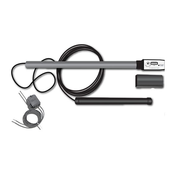
Kit Includes:
• Wireless vehicle sensor with direct burial coil assembly and a plug-in electronics/transmitter
module designed for mounting up to 15 feet away from the pavement edge.
• RB709U-NB two channel receiver with instructions.
• Two size AA batteries.
• GTO Wireless Exit Sensor instruction manual for general installation guidance.
Thank you for purchasing the GTO Wireless Exit Sensor. Please read the directions carefully and completely before installing.
How it works:
The GTO wireless exit sensor consists of a vehicle sensor, transmitter, and programmable dip switches.
The maximum range between transmitter and receiver is 80-100 ft.
The transmitter module transmits a special GTO transmitter code with additional information to tell the receiver
that this device should be treated as a "free exit" device. The latest GTO gate operators with blue control boards
(GTO "GEN3") are able to decode this format and recognize the device as a free exit or open only command
without the use of the RB709U-NB receiver. This will simplify installations so only the original receiver will be
required.
The RB709U-NB receiver will be required unless you have the GEN 3 (blue board). The RB-709U-NB has two
channels that can be programmed to operate a remote transmitter or keypad and wireless wand. For instance,
Channel 1 could be wired to the Cycle and COM accessory terminals and could be programmed to operate a
transmitter and keypad. Channel 2 could be wired to the Exit and COM accessory terminals and could be used
to operate the wireless exit sensor. Depending on the frequency of use (vehicle traffic) the two AA batteries will
last about 1 to 3 years.
For more information on GTO's full line of automatic gate openers and access controls visit our website at www.gtoaccess.com
I N S T A L L A T I O N M A N U A L
RB709U-NB
Universal Receiver
ACCESS
SYSTEMS
Electronics/Transmitter
Module
MIN
SENSITIVITY
Vehicle Sensor
Programmable
Dip Switches
TRANSMITTER
TRANSMITTER
TRANSMIT
MAX
CODE
ACTIVE
GTO WIRELESS EXIT WAND
MIN
MAX
CODE
SENSITIVITY
GTO WIRELESS EXIT WAND
Module Cover
Rev. 12/01/08 • Printed in China for GTO, Inc.
TRANSMIT
ACTIVE
Advertisement

Related Manuals for GTO Wireless Exit Sensors GTO


Summary of Contents for GTO Wireless Exit Sensors GTO
- Page 1 (GTO “GEN3”) are able to decode this format and recognize the device as a free exit or open only command without the use of the RB709U-NB receiver. This will simplify installations so only the original receiver will be required. The RB709U-NB receiver will be required unless you have the GEN 3 (blue board). The RB-709U-NB has two channels that can be programmed to operate a remote transmitter or keypad and wireless wand. For instance, Channel 1 could be wired to the Cycle and COM accessory terminals and could be programmed to operate a transmitter and keypad. Channel 2 could be wired to the Exit and COM accessory terminals and could be used to operate the wireless exit sensor. Depending on the frequency of use (vehicle traffic) the two AA batteries will last about 1 to 3 years. For more information on GTO's full line of automatic gate openers and access controls visit our website at www.gtoaccess.com ACCESS SYSTEMS Electronics/Transmitter Module RB709U-NB Vehicle Sensor Programmable Dip Switches TRANSMITTER...
-
Page 2: Sensor Placement
• Locate the SENSOR away from general moving traffic to prevent unwanted activation. Remember that the SENSOR detects MAGNETIC DISTURBANCES caused by a vehicle’s mass and velocity. • Range distance is approximate and will vary due to outside interference, type of soil, vehicle mass, speed, etc. • It is recommended that you run the Signal Cable inside PVC conduit to prevent accidental damage. • Do not run Signal Cable in conduit with other wires such as AC power or other control wires. • The SIGNAL CABLE CANNOT BE SPLICED. If you need more wire, contact the GTO Sales Department at 1-800-543-GATE (4283). RANGE: 12 ft. radius (max) W i r e l e s s E x i t S e n s o r NOTE: Place the transmitter on the same side of the driveway in the line of sight of the receiver to maximize the range. - Page 3 Transmitter Module Placement Determining Transmitter Module Location • Choose a location for the transmitter module that is far enough from the driveway edge that vehicles are unlikely to hit it. Fifteen feet of wire is included to allow the transmitter to be 12 to 15 feet from the driveway. To test the chosen location to be sure it is free from obstructions or other interference, you can use your remote control transmitter at the same height as the transmitter module to activate the gate. Receiver • NOTE: For GTO Receiver #AQ201-NB (Grey in Color) R4500 Wireless Wand is “plug and play” and will work. For GTO Receiver #A2Q201 (Black) and all other model receivers, enclosed RB709U-NB is required. • After laying the vehicle sensor in the hole adjacent to the driveway. Run the signal cable to the transmitter module in the narrow trench. Do not fill the hole or trench until satisfactory operation is verified. Install the Vehicle Sensor DO NOT fill the hole until final testing is complete.
- Page 4 Connecting the Electronics/Transmitter Module 6 inches deep Sensor SENSITIVITY GTO WIRELESS EXIT WAND • Feed the Signal Cable through the PVC pipe and plug into the connector at the bottom of the Electronics/Transmitter module. W i r e l e s s E x i t S e n s o r TRANSMITTER TRANSMIT ACTIVE...
- Page 5 • This completes the hardware installation. TRANSMITTER TRANSMIT CODE SENSITIVITY GTO WIRELESS EXIT WAND W i r e l e s s E x i t S e n s o r Dip Switches Transmit Indicator ACTIVE NOTE: The module should extend out...
- Page 6 To use or not to use the Included Receiver Depending on the type of control board you are using you may or may not need to use the RB709U-NB universal receiver included with the Wireless Exit Sensor. • Post mount operators with a GEN-3 Blue Control Board DO NOT require that you use the RB709U-NB universal receiver. (See the pictures below to determine if you have a GEN-3 Blue Control Board). • ALL PAD MOUNT OPERATORS will require the use of the RB709U-NB universal receiver.
- Page 7 TRANSMITTER 1 2 3 4 5 6 7 8 TRANSMIT CODE ACTIVE GTO WIRELESS EXIT WAND STALL FORCE RECEIVER GTO/PRO1000, SL1000/2000 Connections W i r e l e s s E x i t S e n s o r...
-
Page 8: Normal Operation
NOTE: This equipment has been tested and found to comply with the limits for a Class B digital device, pursuant to Part 15 of the FCC Rules. These limits are designed to provide reasonable protection against harmful interference in a residential installation. This equipment generates, uses and can radiate radio frequency energy and, if not installed and used in accordance with the instructions, may cause harmful interference to radio communications. However, there is no guarantee that interference will not occur in particular installations. If this equipment does cause harmful interference to radio or television reception, which can be determined by turning the equipment off and on, the user is encouraged to try to correct the interference by one or more of the following measures: • Reorient or replace the receiver antenna. • Increase the separation between the equipment and the receiver. • Connect the equipment into an outlet on a circuit different from that to which the receiver is connected. • Consult the dealer or an experienced radio/TV technician for help. This product and any accessory you purchase should only be installed on a gate opener that meets the current safety standard, UL325, 4th Edition. If you have a gate opener that is not listed with the current standard please contact the GTO sales department for consultation on a gate opener that can meet your specific needs. W i r e l e s s E x i t S e n s o r TRANSMITTER SENSITIVITY GTO WIRELESS EXIT WAND... - Page 9 When an EXIT SENSOR is in use, the automatic gate opener could be activated by a child on a bicycle, tricycle or other metal play equipment. This product is not recommended for applications exposed to children. Limited One Year Warranty GTO, Inc., gate openers and accessories are covered under warranty by the manufacturer against defects in materials and manufacturer workmanship for a period of one (1) year from date of purchase, provided the recommended installation procedures have been followed. In the case of product failure due to defective material or manufacturer workmanship within the one (1) year warranty period, the product will be repaired or replaced (at the manufacturer’s option) at no charge to the customer, if returned freight prepaid to GTO, Inc., 3121 Hartsfield Road, Tallahassee, Florida, USA 32303. IMPORTANT: Call (800) 543-1236 for a Return Goods Authorization (RGA) number before returning accessory to factory. Products received at the factory without an RGA number will not be accepted. Replacement or repaired parts are covered by this warranty for the remainder of the one (1) year warranty period or six (6) months, whichever is greater. GTO, Inc. will pay the shipping charges (equal to United Parcel Service GROUND rate) for return to the owner of items repaired under warranty. The manufacturer will not be responsible for any charges or damages incurred in the removal of the defective parts for repair, or for the reinstallation of those parts after repair. This warranty shall be considered void if damage to the product(s) was due to improper installation or use, connection to an improper power source, or if damage was caused by lightning, wind, fire, flood, insects or other natural agent. After the one (1) year warranty period, GTO, Inc. will make any necessary repairs for a nominal fee. Call GTO at (800) 543-1236 for more information. This warranty gives you specific legal rights, and you may also have other rights which may vary from state to state. This warranty is in lieu of all other warranties, expressed or implied. NOTE: Verification of the warranty period requires copies of receipts or other proof of purchase. Please retain these records.
Need help?
Do you have a question about the Wireless Exit Sensors GTO and is the answer not in the manual?
Questions and answers