Table of Contents
Advertisement
When an EXIT WAND is in use, the automatic gate opener could be activated by a
child on a bicycle, tricycle or other metal play equipment. This product is not recom-
mended for applications exposed to children.
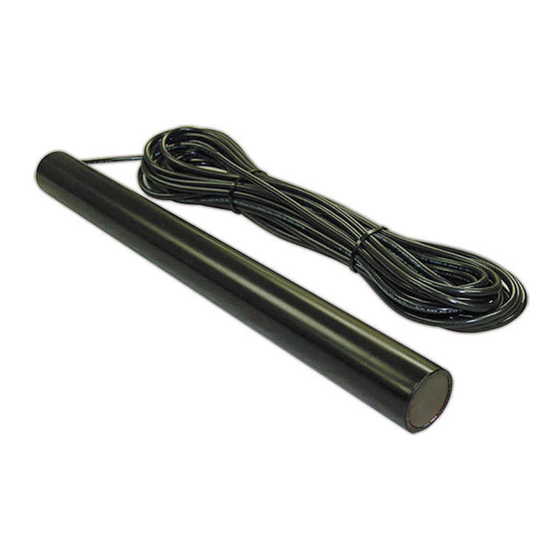
Parts Identification:
Double Spade
Connectors (2)
Battery Connection
Wires (2)
GTO, Inc. • 3121 Hartsfield Road • Tallahassee, Florida 32303
1-800-543-GATE (4283) • Technical Support 1-800-543-1236
EXIT WAND
Installation Manual
WARNING
WAND with 50, 100 or 150 feet
of Direct Burial Cable
Ty-Wraps (4)
www.gtopro.com
WARNING
!
WARNING
GATE OPENING SENSOR IN USE
The Automatic Gate Opener is activated when a
vehicle comes within range of the sensor buried
along side the driveway and could possibly be
activated by a child on a bicycle, tricycle or other
metal play equipment.
Warning Signs (2)
Wire Nuts (3)
Adjustment Board
Wire Clamp
Range
RWINSTMM
rev-5/18/07
Advertisement
Table of Contents

Related Manuals for GTO FM139


Summary of Contents for GTO FM139
-
Page 1: Parts Identification
WAND with 50, 100 or 150 feet of Direct Burial Cable Double Spade Connectors (2) Battery Connection Wires (2) GTO, Inc. • 3121 Hartsfield Road • Tallahassee, Florida 32303 1-800-543-GATE (4283) • Technical Support 1-800-543-1236 WARNING WARNING WARNING GATE OPENING SENSOR IN USE... -
Page 2: Table Of Contents
EXIT WAND. This product requires no maintenance and will give you years of enjoyment by providing hands free operation of your gate. GTO, Inc., has been designing and manufacturing reliable, high quality products since 1987. Our corporate headquarters and state of the art manufacturing facility is located in Tallahassee, Florida. - Page 3 After the one (1) year warranty period, GTO, Inc. will make any necessary repairs for a nominal fee. Call GTO at (800) 543-1236 for more information.
-
Page 4: Before You Start
Before You Start ... Please read the instructions completely before you begin the installation. Terms and Definitions: • METAL OBJECT: anything that is made of iron-based metal, from a child’s toy to a car or truck. • WAND: the magnetic device inside the waterproof tube that detects METAL OBJECTS in motion. •... -
Page 5: Installation Overview
• It is recommended that you run the Wand cable inside PVC conduit. • Do not run Wand cable in conduit with other wires such as AC power or other control wires. • The Wand cable CANNOT be spliced. If you need more wire, contact the GTO Sales Department at 1-800-543-GATE (4283). -
Page 6: Installing The Exit Wand
Installing the Exit Wand... Determining WAND Location: IMPORTANT: Clear an area 20 feet in all directions of metal tools, toys and automobiles, to prevent magnetic disturbance during testing and installation. Step 1: Determine the optimum location for the EXIT WAND using the information found in “Placement of the WAND”... -
Page 7: Wiring The Wand To The Gto/Pro Opener
Wiring the WAND to GTO/PRO Gate Openers: IMPORTANT: TURN OFF the connect the battery wires b efore you begin to connect the WAND wires to any gate opener. Step 5: Run the cable from the WAND through a WIRE CLAMP into the control box. Pull about 8 - 10 inches... -
Page 8: Connecting The Range Adjustment Control Board
Connecting the Range Adjustment Control Board: Step 9: Connect the YELLOW wire from the WAND CABLE to the YELLOW wire from the Range Adjustment control board using one of the WIRE NUTS provided. Step 10: Connect the BLACK wire from the Range Adjustment control board to the BLACK BATTERY CONNECTOR wire (provided), along with the SHIELD wire from the WAND CABLE (see Step 13 below). -
Page 9: Powering Up The Wand
Powering Up the WAND: IMPORTANT: When the WAND is first powered up it must be undis- turbed for 60 seconds to perform the self test and calibrations. Before powering the WAND make sure there are no moving metal objects or moving vehicles within range of the WAND. -
Page 10: Installation On Other Brand Gate Openers
For Installation on Other Brand Gate Openers ... If you are using the EXIT WAND low for wiring the system. If you do not understand the instructions below, please call GTO’s Techni- cal Support at 1-800-543-1236. Typical Gate Wiring Connection: •... -
Page 11: Technical Specifications
TECHNICAL SPECIFICATIONS: • Power supply: 8-26 Vac/dc. • Current consumption: 1.5 mA typical. • Relay rating: Latching relay. Nominal switching capacity (resistive load) Max. switching power (resistive load) Max. switching voltage Max. switching current • Relay Trip Time: 2 seconds. •... -
Page 12: Other Gto Products
If your gate application is far away from an AC power outlet, or greater than 1,000 ft (304.8m), you can choose to power your GTO/PRO gate operator system with these high output GTO/PRO solar panels. Each solar panel comes with tubular steel support, mounting clips, wire connectors, and 8 ft of Low Voltage Wire (RB509).
Need help?
Do you have a question about the FM139 and is the answer not in the manual?
Questions and answers