
Related Manuals for Panasonic WV-CP450


Summary of Contents for Panasonic WV-CP450
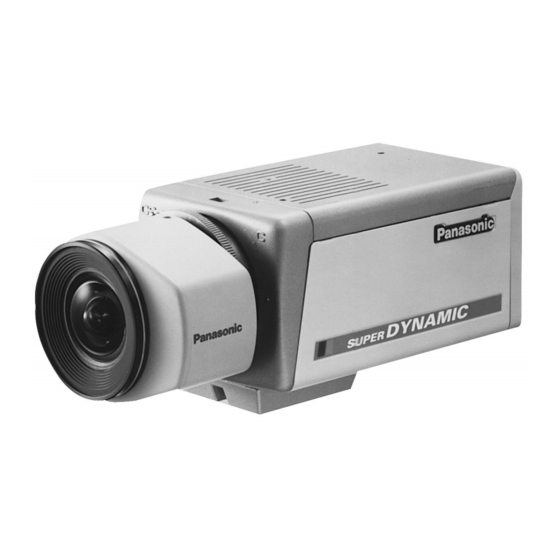
- Page 1 Colour CCTV Cameras WV-CP450/WV-CP454 (Lens : option) Before attempting to connect or operate this product, please read these instructions completely.
- Page 2 ENGLISH VERSION For U.K. FOR YOUR SAFETY PLEASE READ THE FOLLOWING TEXT CARE- FULLY. WARNING CAUTION THIS APPARATUS MUST BE EARTHED RISK OF ELECTRIC SHOCK DO NOT OPEN IMPORTANT The wires in this mains lead are coloured in accordance with the following code.
- Page 4 We declare under our sole responsibility that the product to Vi deklarerar härmed värt fulla ansvar för att den produkt till which this declaration relates is in conformity with the stan- vilken denna deklaration hänvisar är i överensstämmelse med dards or other normative documents following the provisions of standarddokument, eller andra normativa dokument som Directives EEC/73/23 and EEC/89/336.
-
Page 5: Table Of Contents
CONTENTS PREFACE ..................................3 FEATURES ..................................3 PRECAUTIONS ................................4 MAJOR OPERATING CONTROLS AND THEIR FUNCTIONS ..................5 CONNECTIONS ................................8 FOCUS OR BACK FOCAL ADJUSTMENT ........................12 INSTALLATION OF CAMERA ............................13 SET UP ..................................14 1. CAMERA SETUP MENU ............................14 2. -
Page 6: Preface
PREFACE Panasonic's WV-CP450 series colour digital camera (picture elements), and digital signal processing LSI's. introduces a new level of high picture quality and high This model offers cutting-edge technology resolution through the use of a 1/3-inch interline trans- advanced video surveillance. -
Page 7: Precautions
90%. The input power source is shock. 220 - 240V AC 50Hz for WV-CP450 and DC 12V/AC 24V for WV-CP454. 4. Do not use strong or abrasive detergents when cleaning the camera body. -
Page 8: Major Operating Controls And Their Functions
MAJOR OPERATING CONTROLS AND THEIR FUNCTIONS MAJOR OPERATING CONTROLS AND THEIR FUNCTIONS <WV-CP450> POWER 220ー240V AC 50H VIDEO OUT GEN-LOCK DYNAMIC SUPER CP450 <WV-CP454> POWER DC 12V AC 24V VIDEO OUT Hi-Z G/L 75Ω GEN-LOCK Slide the panel to the left until it locks. - Page 9 q Auto Iris Lens Connector u Left Button ( This connector is used to connect with the auto iris This button is used to move the cursor to the left. It lens by a 4-pin male connector that is supplied as also selects the mode and can be used to adjust a standard accessory (Part No.
- Page 10 !3 Video Output Connector (VIDEO OUT) Caution: This connector is used to connect with the VIDEO Connect to 12V DC (10.5V-16V) or 24V AC IN connector of the monitor. (19.5V-28V) class 2 power supply only. Make sure to connect the grounding lead !4 Power Cord Socket to the GND terminal when the power is This socket is used to connect the power cord...
-
Page 11: Connections
CONNECTIONS Resistance of copper wire [at 20°C (68°F)] A. WV-CP450 (220 - 240V AC 50Hz) 1. Connect the AC power cord (supplied as standard Copper wire size (AWG) (0.22mm (0.33mm (0.52mm (0.83mm accessory) to the power cord socket of the cam- era. - Page 12 2. 24 V AC Power Supply Video Cable Connect the power cable to the AC/DC compatible 1. It is recommended to use a monitor whose resolu- input terminal on the rear panel of the camera. tion is at least equal to that of the camera. 2.
- Page 13 Installation of Auto Iris Lens Connector Type of RG-59/U RG-6U RG-11/U RG-15/U coaxial cable (3C-2V) (5C-2V) (7C-2V) (10C-2V) Install the lens connector (YFE4191J100) when using a Recommended video drive ALC lens. maximum cable length (ft) 1 650 1 980 2 640 The installation should be made by qualified ser- vice personnel or system installers.
- Page 14 (2) After connection, assemble the lens connector as Mounting the Lens follows. Caution: Before you mount the lens, loosen the two screws on the ring, and rotate this ring clockwise until it Connector stops. If the ring is not at the end, the inner glass Cover Automatic Iris Lens...
-
Page 15: Focus Or Back Focal Adjustment
Caution for Mounting the Lens FOCUS OR BACK FOCAL ADJUSTMENT The lens mount should be a C-mount or CS-mount (1”- The following adjustment should be made by qualified 32UN) and the lens weight should be less than 450g service personnel or system installers. (0.99 lbs). -
Page 16: Installation Of Camera
INSTALLATION OF CAMERA • Mounting from the bottom • Mounting from the top This camera is designed to be mounted from the Remove the mount adapter from the bottom of the bottom, as shown below. The mounting hole is a camera by removing the two fixing screws. -
Page 17: Set Up
SET UP 1. CAMERA SETUP MENU This camera utilizes a user setup menu that is displayed on-screen. The setup menu contains various items that form a tree-type structure as shown below. It menu is described in the following section : "2. SETUP OPERATION". CAM SET UP SET UP DISABLE →... - Page 18 Lens Drive White Special Signal Balance menu Selection Video Manual Manual Chroma Level Level Gain Gain Pedestal Adjustment Adjustment Manual Manual Mask Area Mask Area Selection Selection -15-...
-
Page 19: Setup Operation
2. SETUP OPERATION ter changes each time this button is pressed. This camera utilizes a user setup menu (CAM SET UP) Left Button ( This button is used to move the that is displayed on the monitor. cursor to the left. Use this button To set items on the CAM SET UP menu, use the follow- to select or adjust the parameters ing buttons on the side panel. - Page 20 • Opening the Setup Menu ** CAM SET UP ** Press and hold down for a second or longer. CAMERA ID ALC/ELC SHUTTER Blinking ** CAM SET UP ** SYNC CAMERA ID WHITE BAL ALC/ELC LENS DRIVE SHUTTER SET UP DISABLE SYNC WHITE BAL LENS DRIVE...
- Page 21 Important Notice: When the cursor is moved to END and the CAM ** CAM SET UP ** ** CAM SET UP ** CAMERA ID CAMERA ID SET UP menu closed after changing the parame- ALC/ELC ALC/ELC ters, the new values are stored in the EEPROM SHUTTER SHUTTER (Electric Erasable and Programmable Read Only...
-
Page 22: Setting Procedures
SETTING PROCEDURES Character Cursor 1. Camera Identification (CAMERA ID) Setting 0123456789 You can use the camera identification (CAMERA ID) to ABCDEFGHIJKLM NOPQRSTUVWXYZ Character assign a name to the camera. The camera ID consists ().,'":;&#!?= Area of up to 16 alphanumeric characters. You can select +-*/%$ÄÜÖÆÑÅ... - Page 23 Blinking ALC: If you use the auto iris lens, select this parameter. ELC: If you use a fixed or manual iris lens, select this parameter. ** CAM SET UP ** WV-CP450 CAMERA ID ALC/ELC SHUTTER SYNC WHITE BAL LENS DRIVE 2.
- Page 24 2-1. ALC Mode with SUPER-D ON Super Dynamic Function (SUPER-D) ** ALC CONT ** BACK LIGHT COMP The important object in a scene is usually placed in the SUPER-D centre of the monitor’s screen. In SUPER-D mode, MASK SET more photometric weight is given to the centre of the LEVEL ...I..
- Page 25 2-2. ALC Mode with SUPER-D OFF and ELC Blinking Mode Note: If ELC is selected, set MASK SET according to this procedure. 1. Move the cursor to the SUPER-D parameter and select OFF. (When you select ELC, SUPER-D is not available.) The item MASK SET appears on the menu.
- Page 26 4. Repeat step 1 to 3 to mask the desired area.To 3. Shutter Speed Setting (SHUTTER) cancel masking, move the cursor to that area and Note: When ON is selected for SUPER-D on the ALC press CONT menu, this item is not available. To select electronic shutter speed, select OFF for Turns to white SUPER-D in the menu.
- Page 27 4. Gain Control Setting (AGC ON/OFF) 5. Synchronization Setting (SYNC) You can set the gain (brightness level portion of an You can select internal sync mode (INT) or line-lock image) to automatic level adjustment (ON) or fixed mode (LL). Additionally, this model accepts the VBS level(OFF).
- Page 28 Important Notice: 6. The VS gen-lock mode has its own menu for hori- 1. The priority for the sync modes is as follows. zontal phase adjustments. When the cable length 1. Multiplexed Vertical Drive (VD2) (Highest pri- of the video output or the gen-lock input is changed, the horizontal phase must be re-adjust- ority) 2.
- Page 29 3. Confirm that the INT parameter changed to EXT 8. Adjust the horizontal phase by pressing (VBS) on the menu. . The adjustable range is 0 - 2.0µs. Caution: The gen-lock input signal should meet 9. Move the cursor to SC COARSE. The cursor starts the EIA RS-170A specifications and should blinking.
- Page 30 Switcher, as closely as possible to the colour of 5-2. VS Gen-lock Mode (EXT(VS)) the original scene. 1. Move the cursor to the SYNC parameter and The SC FINE adjustment has a range of 90 select INT. degrees of colour shift. 2.
- Page 31 2. After confirming the cursor is on LL, press ** SYNC ** The vertical phase adjustment menu appears on the monitor. H PHASE ..I ** SYNC ** V PHASE COARSE 1(1--16) FINE I..5. Move the cursor to H PHASE. The cursor starts blinking.
- Page 32 • To reset COARSE and FINE to the values pre- set at the factory, press simultane- 1 (1 - - 16): 0 degrees ously. COARSE and FINE adjustments are preset at the factory to zero-crossing of the 2 (1 - - 16): 22.5 degrees AC line phase.
- Page 33 Move the cursor to the WHITE BAL parameter and 2. Press to start the white balance setup. The select ATW. The white balance of the camera is words PUSH SW start blinking to indicate that the automatically set. white balance is being set. ** CAM SET UP ** ** CAM SET UP ** CAMERA ID...
- Page 34 Fine Adjustment for AWC (ATW) Manually 7. Lens Drive Signal Selection (LENS DRIVE) You can add the detailed setting for white balance set- ting manually. This item is used to select the type of auto iris lens 1. To set MASK SET, proceed as described in steps drive signal to be supplied to the lens from the auto iris 1 to 4 of “ALC mode with SUPER-D OFF and ELC lens connector.
- Page 35 8. Special Menu 8-3. Pedestal Level Setting (PEDESTAL) 1. Move the cursor to the PEDESTAL parameter. This menu lets you adjust and set up the video signal 2. While observing the waveform monitor/oscillo- of the camera to meet your requirements. scope or video monitor, move the “I”...
-
Page 36: Prevention Of Blooming And Smear
PREVENTION OF BLOOMING AND SMEAR When the camera is aimed at a bright light, such as a spotlight, or a surface that reflects bright light, smear or blooming may appear. Therefore, the camera should be operated carefully in the vicinity of extremely bright objects to avoid smear or blooming. -
Page 37: Specifications
SPECIFICATIONS Pick-up Device: 752 (H) x 582 (V) pixels, Interline Transfer CCD Scanning Area: 4.9 (H) x 3.7 (V) mm (Equivalent to scanning area of 1/3” pick-up tube) Scanning: 625 lines / 25 fields / 25 frames Horizontal: 15.625 KHz Vertical: 50.00 Hz Synchronization:... - Page 38 Power Source and WV-CP450: 220 - 240V AC 50 Hz, 5.3W Power Consumption: WV-CP454: 24V AC 50 Hz, 5.2W 12V DC, 540 mA Dimensions (without lens): 67 (W) x 55 (H) x 123 (D) mm [2-5/8” (W) x 2-3/16” (H) x 4-13/16” (D)]...
-
Page 39: Standard Accessories
STANDARD ACCESSORIES Body Cap ................1 pc. ALC Lens Connector (YFE4191J100) ........1 pc. AC Power Cord (for only WV-CP450)........1 pc. OPTIONAL ACCESSORIES Lenses : WV-LA2R8C3B, WV-LA4R5C3B, WV-LA9C3B, WV-LA210C3, WV-LA408C3, WV-LA908C3 WV-LZ61/10, WV-LZ62/2, WV-LF4R5C3A, WV-LF9C3A -36-... - Page 40 Matsushita Electric Industrial Co., Ltd. Central P.O. Box 288, Osaka 530-91, Japan N0797-1087 YWV8QA4715BN Printed in Japan N 30 Gedruckt in Japan Imprimé au Japon Impreso en Japón...
Need help?
Do you have a question about the WV-CP450 and is the answer not in the manual?
Questions and answers