Sonel MRU-30 User Manual
Earth resistance metr
Hide thumbs
Also See for MRU-30:
- Operation manual (56 pages) ,
- Operation manual (52 pages) ,
- User manual (56 pages)
Table of Contents
Advertisement
Quick Links
Advertisement
Table of Contents

Related Manuals for Sonel MRU-30


Summary of Contents for Sonel MRU-30
- Page 2 MRU-30 – USER MANUAL...
- Page 3 USER MANUAL EARTH GROUND RESISTANCE METER MRU-30 SONEL S. A. Świdnica, Poland SONEL TEST & MEASUREMENT Santa Clara, CA 95054 Version 1.05 26.07.2021...
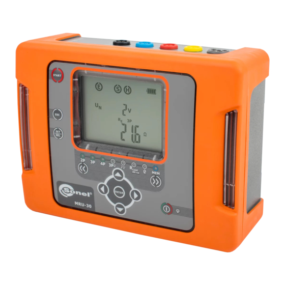
- Page 4 The Sonel MRU-30 meter is an easy-to-use instrument that is designed for the safe measurement of earth ground resistance. The MRU-30 uses established methods of earth ground resistance measurements such as 3-pole, 4- pole, and 3-pole with auxiliary clamp. Additionally the MRU-30 employs the two clamp method of measurement without the use of auxiliary test rods when rods can't be used in some situations.
-
Page 5: Table Of Contents
Influence of the serial interference voltage U on earth resistance measurements for 3P+C, ρ ................. 47 methods R 3P, R 4P, R 12.2.2 Influence of the auxiliary electrodes on earth resistance measurements for methods 3P+C, ρ ....................47 3P, R 4P, R MRU-30 – USER MANUAL... - Page 6 Additional uncertainties in accordance with IEC 61557-5 (R 3P, R 4P) ....... 48 13 Accessories ....................49 13.1 Standard accessories ..................... 49 13.2 Optional accessories ....................49 14 Manufacturer ....................50 15 Laboratory services ..................51 MRU-30 – USER MANUAL...
-
Page 7: Safety
The MRU-30 meter has been designed for measurements of earth/ground connections, equipoten- tial bonding, and ground resistivity. Any application or use of the MRU-30 that differs from those specified in this manual may result in damage to the meter and constitute a source of danger to the user. -
Page 8: Turning The Meter On And Activating The Screen Backlight
Turn on the meter by pressing the button and the SET/SEL button simulta- neously. When the Fn screen is displayed use the buttons to set the local mains frequency – 50 Hz or 60 Hz (50 Hz is set as default). MRU-30 – USER MANUAL... - Page 9 (Auto-OFF): Use the buttons to set the time to turn the meter off automatically (Auto-OFF): The choices are 300 s, 600 s, 900 s or none (dashes - Auto-OFF is disa- bled). MRU-30 – USER MANUAL...
- Page 10 After changing the parameters, to exit the SETUP menu, either: Press the ENTER button to memorize set- tings (not applicable for the Update screen) Or: press the ESC button to go to the meas- urement screen without confirming changes. MRU-30 – USER MANUAL...
-
Page 11: Measurements
4P, R 3P+C, R CONT and ρ, and before pressing the START button the MRU-30 monitors the voltage pre- sent on the measurement terminals (between E and other sockets) and displays the value of the interfering voltage on the screen. -
Page 12: Earth Resistance Measurement With 2-Pole Method (R 2P)
25 V or 50 V. Press ENTER to save the setting or press ESC to exit without saving. Connect the test leads according to the drawing. The meter is ready for measurement. Press START to begin measurement. MRU-30 – USER MANUAL... -
Page 13: Earth Resistance Measurement With 3-Pole Method (R 3P)
Results may be affected by additional uncer- tainty. 4.3 Earth resistance measurement with 3-pole method (R The basic type of earth ground resistance measurement is the 3-pole measurement. Disconnect the earth electrode object of test. MRU-30 – USER MANUAL... - Page 14 Drive the voltage electrode into the ground and connect it to the S terminal of the meter. Connect the earth electrode object of test to the E terminal of the meter. All 3 electrodes should be aligned in a straight line. The meter is ready for measurement. MRU-30 – USER MANUAL...
- Page 15 (such a situation occurs often if the earth electrode is properly made and the upper layer of the ground is dry and characterized by a low conductivity). Then the relation between the electrode resistance and the resistance of the measured earthing is MRU-30 – USER MANUAL...
- Page 16 The resistance of H and S electrodes, or one of them ex- and R or R along ceeds 19.9 kΩ. The measurement is subject to error. with Ω value Flashing symbols: Flashing symbols E, H, S, indicate a test lead is discon- nected from the measurement terminals. MRU-30 – USER MANUAL...
-
Page 17: Earth Resistance Measurement With 4-Wire Method
Connect the earth electrode object of test to the E terminal of the meter. Connect the ES terminal to the earth electrode object of test below the E connection. All 3 electrodes should be aligned in a straight line. MRU-30 – USER MANUAL... - Page 18 If the R test results differ by more than 3% it is necessary to significantly increase the distance be- tween the current electrode and the earth elec- trode object of test (E) and repeat the measure- ments. MRU-30 – USER MANUAL...
- Page 19 19.9 kΩ. The measurement is subject to error. and R or R along with Ω value Flashing symbols: Flashing symbols E, Es, H, S, indicate a test lead is dis- connected from the measurement terminals. MRU-30 – USER MANUAL...
-
Page 20: Earth Resistance Measurement With 3-Pole Method With Additional Clamp (R E 3P+C)
Connect the earth electrode object of test to the E terminal of the meter. Attach the receiving clamp around the earth electrode object of test below the E cable connection. All 3 electrodes should be aligned in a straight line. MRU-30 – USER MANUAL... - Page 21 - resistance of voltage electrode ER – additional uncertainty caused by the re- sistance of the electrodes – interfering (noise) voltage – leakage current. The result is displayed for 20 seconds. Press ENTER to display again. MRU-30 – USER MANUAL...
- Page 22 – banana plug – electrode are not corroded or loosened. In most cases the achieved resolution of the measurement is sufficient, but it is necessary to be conscious of the uncertainty the measurement is burdened with. MRU-30 – USER MANUAL...
- Page 23 Flashing clamp Current clamp disconnected or the current value meas- ured by the clamp is too low. symbol Interfering current exceeds 3 A – the measurement is not xxA , I>3A, possible. MRU-30 – USER MANUAL...
-
Page 24: Earth Resistance Measurement With Two-Clamp Method (2C)
Attach the transmission clamp and the measurement clamp around the tested earth electrode object of test at least 30 cm / 12 in from each other. The meter is ready for measurement. Press START to begin measurement. MRU-30 – USER MANUAL... - Page 25 Measurement range exceeded. Flashing clamp symbols Transmitting clamp disconnected. Receiving clamp disconnected, or the measured current value is too low. Flashing clamp symbol Interfering current is > 3 A. The measurement cannot pro- xxA , I>3A, ceed. MRU-30 – USER MANUAL...
-
Page 26: Calibration Of The Measurement Clamp C-3
The meter has determined the correction factor for connected clamp. The factor is saved in the memory also when the power supply of the meter is off until the following successful calibration of the clamp has been performed. MRU-30 – USER MANUAL... - Page 27 - Make sure the test lead passes centrally through the clamp. Additional information displayed by the meter Flashing symbols: Flashing symbols E, H, indicate a test lead is disconnected from the measurement terminals. oPEn Flashing clamp sym- Measurement clamp is disconnected. MRU-30 – USER MANUAL...
-
Page 28: Measurement Of Resistance Of Protective Conductors And Equipotential Bonding
The meter is now in the state of measuring interfering noise voltage between the measurement terminals. Connect the test leads according to this diagram: The meter is ready for measurement. Press START to begin measurement. MRU-30 – USER MANUAL... - Page 29 > 3 V, but < 40V. The measurement cannot proceed. The value of the interfering voltage is < 3 V, but has a high ‘NOISE!’ value. Results may be affected by additional uncertainty. MRU-30 – USER MANUAL...
-
Page 30: Calibration Of The Test Leads For R
The results now include the cor- rection value for R and is indi- CONT cated by AUTO-ZERO displayed on screen. This value is saved in memory and will be overwritten whenever the Auto-Zero proce- dure is performed MRU-30 – USER MANUAL... -
Page 31: Earth Resistivity Measurement (Ρ)
Use the button to select the test volt- age. Use the buttons to select the measurement voltage value of 25 V or 50 V. Press ENTER to save the setting or press ESC to exit without saving. MRU-30 – USER MANUAL... - Page 32 Connect the voltage electrode to the ES socket of the meter, Connect the current electrode to the E socket of the meter. The meter is ready for measurement. Press START to begin measurement. After the measurement completes view the results on the screen. MRU-30 – USER MANUAL...
- Page 33 – banana plug – electrode are not corroded or loosened. In most cases the achieved resolution of the measurement is sufficient, but it is necessary to be conscious of the uncertainty the measurement is burdened with. MRU-30 – USER MANUAL...
- Page 34 R or R along ceeds 19.9 kΩ. The measurement is subject to error. with Ω value Flashing symbols: Flashing symbols E, ES, H, S, indicate a test lead is dis- connected from the measurement terminals. MRU-30 – USER MANUAL...
-
Page 35: Memory Of Measurement Results
Memory of measurement results Measurements can be stored in memory. The MRU-30 has a memory divided into 10 banks of 99 cells each. Each memory cell can store all measurement results of individual tests. Measurement results are stored in a memory cell with a selected number and selected memory bank. The user of the meter can optionally assign memory cell numbers to individual measurement points and the memory bank num- bers to individual facilities. - Page 36 If you try to store data in an occupied memory cell, the OVEr ? warning message will appear: Press ENTER to overwrite the result and save the data, or ESC to cancel and select other cell or bank. MRU-30 – USER MANUAL...
-
Page 37: Viewing Memory Data
To select the bank number Press the SET/SEL button. The bank number will flash. Use the buttons to select the de- sired number of the bank. Viewing test results for R and R 2P measurements is disabled. CONT MRU-30 – USER MANUAL... -
Page 38: Deleting Memory Data
MEM. The LED is illuminated. Set the cell number to be deleted by using the buttons. Press ENTER. The message: ? is displayed. Press ENTER. symbol and dEL ConF ? mes- sages appear. MRU-30 – USER MANUAL... -
Page 39: Deleting Bank Data
SET/SEL button until the bank number flashes. Press the SET/SEL button again. The cell number will flash. Set the cell number to ‘- -’ (before 01) by pressing the button. Then the message is displayed. MRU-30 – USER MANUAL... - Page 40 Press ENTER to delete the selected bank. After deleting the bank the meter beeps three times. Press ESC to can- cel and return to memory browsing. The contents of the bank have been deleted. MRU-30 – USER MANUAL...
-
Page 41: Deleting The Whole Memory
Set the bank number to ‘-’ (before 0) by pressing the but- ton. The bank number will change to ‘-’ Then the message is displayed. Press ENTER. symbol and dEL ConF ? mes- sages appear. MRU-30 – USER MANUAL... -
Page 42: Data Transmission
Data transmission 6.1 Computer connection accessories To operate the meter with a computer, a USB cable and Sonel Reader software is required. If these accessories have not been purchased along with the meter they are available from the Sonel or an authorized Sonel distributor. -
Page 43: Firmware Update
Batteries are nearly discharged No battery symbol on screen (with charger connected) indicates the battery is either disconnected or has malfunctioned. The bAtt message indicates the batteries are completely dis- charged. The meter switches off automatically after 5 seconds. MRU-30 – USER MANUAL... -
Page 44: Charging The Rechargeable Battery Pack
8.2 Charging the rechargeable battery pack CAUTION! The MRU-30 meter is powered from a SONEL NiMH 9.6 V battery pack. It can only be replaced by Sonel or an authorized Sonel service center. The internal battery charger is powered by an external 12 V Sonel AC power supply adapter. The device may be also powered from a 12 V car accessory socket. -
Page 45: General Principles Of Using Ni-Mh Batteries
Only use the maintenance methods described in this manual. The outside of the MRU-30 meter may be cleaned with a soft, damp cloth using all-purpose deter- gents. Do not use any solvents or cleaning agents or abrasives which might scratch the case. -
Page 46: Dismantling And Disposal
2000 Ω to 9999 Ω 1 Ω ±8% m.v. Measurement of resistance of auxiliary electrodes R and R Range Resolution Accuracy 0 to 999 Ω 1Ω ±(5% (R 1.00 to 9.99 kΩ 0.01kΩ 8 digits) 10.0 to 19.9 kΩ 0.1kΩ MRU-30 – USER MANUAL... - Page 47 0.01 kΩm 4P measurement but not less than ±1 digit. 20.0 to 99.9 kΩm 0.1 kΩm 100 to 999 kΩm 1 kΩm distance between measurement probes (L): 1 to 50 m, or 1 to 150 ft MRU-30 – USER MANUAL...
- Page 48 ................20 k signaling of insufficient clamp current ................≤0.5 mA m) power supply ..........rechargeable batteries type SONEL NiMH 9.6 V 2 Ah n) AC adapter for the battery charger ............100 V to 240 V, 50/60 Hz ...........
-
Page 49: Additional Data
R 3P+C The MRU-30 meter may perform a measurement, if the value of the interference current does not exceed 3 A rms and the frequency complies with the value set in the MENU. Additional uncertainty [Ω] 0.00 to 50,00 Ω... -
Page 50: Influence Of Interference Current On The Result Of The Earth Resistance Measurement For Two-Clamp Method (2C)
12.2.4 Influence of interference current on the result of the earth resistance measurement for two-clamp method (2C) The MRU-30 meter may perform a measurement, if the value of the interference current does not exceed 3 A rms and the frequency complies with the value set in the MENU. -
Page 51: Accessories
USB cable – WAPRZUSB Power supply adaptor Z7 – WAZASZ7, Calibration certificate issued by an accredited laboratory, User manual. 13.2 Optional accessories Optional items available from Sonel or authorized Sonel distributors: WASONG80 WACEGN1BB Auxiliary electrode, 80 cm... -
Page 52: Manufacturer
Santa Clara, Ca 95054 USA tel. +1 (408) 898 2215 fax +1 (408) 988 4869 E-mail: testsupport@soneltest.com Web: www.soneltest.com Attention: Service and repairs must be carried out only by Sonel or an authorized Sonel service center. MRU-30 – USER MANUAL... -
Page 53: Laboratory Services
National Metrological Institute. According to ILAC-G24 „Guidelines for determination of calibration intervals of measuring instruments”, SONEL S.A. recommends periodical metrological inspection of the instruments it manufactures no less frequently than once every 12 months. - Page 54 NOTES MRU-30 – USER MANUAL...
- Page 56 MRU-30 – USER MANUAL...
Need help?
Do you have a question about the MRU-30 and is the answer not in the manual?
Questions and answers