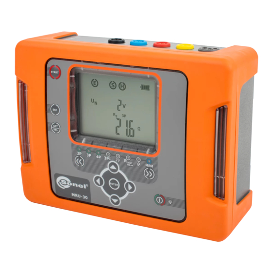
Sonel MRU-30 User Manual
Earth resistance meter
Hide thumbs
Also See for MRU-30:
- Operation manual (56 pages) ,
- Operation manual (52 pages) ,
- User manual (56 pages)
Table of Contents
Advertisement
Quick Links
Advertisement
Table of Contents

Related Manuals for Sonel MRU-30


Summary of Contents for Sonel MRU-30
- Page 2 MRU-30 – USER MANUAL...
- Page 3 USER MANUAL EARTH RESISTANCE METER MRU-30 SONEL S. A. Wokulskiego 11 58-100 Świdnica, Poland Version 1.05 26.07.2021...
- Page 4 The MRU-30 meter is a modern, high quality, easy to use and safe measuring device. Please ac- quaint yourself with the present manual in order to avoid measuring errors and prevent possible prob- lems related to operation of the meter.
-
Page 5: Table Of Contents
Influence of the auxiliary electrodes on earth resistance measurements for methods 3P+C, ρ ....................47 3P, R 4P, R 12.2.3 Influence of the interference current I on the result of the earth resistance for method 3P+C ........................47 MRU-30 – USER MANUAL... - Page 6 12.2.6 Additional uncertainties in accordance with IEC 61557-5 (R 3P, R 4P)......48 13 Accessories ....................49 13.1 Standard accessories ..................... 49 13.2 Optional accessories ....................49 14 Manufacturer ....................50 15 Laboratory services ..................51 MRU-30 – USER MANUAL...
-
Page 7: Safety
The MRU-30 meter has been designed for the purpose of measurements of earth connection and equipotential bonding, and also ground resistivity, Any application that differs from those specified in the present manual may result in a damage to the device and constitute a source of danger for the user. -
Page 8: Turning The Meter On And Activating Screen Backlit
Meter configuration Turn on the meter by pressing and keeping SET/SEL button pressed. When the Fn screen is displayed use to set mains frequency – 50 Hz or 60 Hz (50 Hz is set as default). MRU-30 – USER MANUAL... - Page 9 (Auto-OFF): 300 s, 600 s, 900 s or none (dashes - Auto-OFF is disabled). This function turns off the meter automati- cally after the certain (set by user) period of time. MRU-30 – USER MANUAL...
- Page 10 7. After changing the parameters, you may exit SETUP menu: Press ENTER button to memorize settings (not applicable for Update screen) or use ESC button to go to the measurement screen without confirming the changes. MRU-30 – USER MANUAL...
-
Page 11: Measurements
4P, R 3P+C, R CONT ment with the START button, MRU-30 is monitoring the voltage present on the measurement points (between E and other sockets). The value of the interfering voltage is displayed on screen. Additional information displayed by the meter >100V, >100V and... -
Page 12: Earth Resistance Measurement With 2-Pole Method (R 2P)
25 V or 50 V. Press ENTER to confirm settings or press ESC to exit without saving the changes. Connect test leads according to the drawing. The meter is ready for measurement. Press START to commence measure- ment. MRU-30 – USER MANUAL... -
Page 13: Earth Resistance Measurement With 3-Pole Method (R 3P)
4.3 Earth resistance measurement with 3-pole method (R The basic type of the earth resistance measurement is 3-pole measurement. Disconnect the tested earth electrode for the object installation. MRU-30 – USER MANUAL... - Page 14 Connect the voltage electrode driven into ground to the S socket of the meter, Connect the tested earth electrode to the E socket of the meter. The tested earth electrode as well as the current electrode and voltage electrode should be aligned. The meter is ready for measurement. MRU-30 – USER MANUAL...
- Page 15 (such a situation occurs often if the earth electrode is properly made and the upper layer of the ground is dry and characterized by a low conductivity). Then the relation between the electrode re- MRU-30 – USER MANUAL...
- Page 16 Ω value Flashing symbols: Flashing symbols E or H or S, or both of them, or all three at the same time – one or two or three test leads are dis- connected from the measurement sockets. MRU-30 – USER MANUAL...
-
Page 17: Earth Resistance Measurement With 4-Wire Method (R 4P)
Connect the tested earth electrode to the E socket of the meter. Connect the ES socket to the earth electrode In question below the E cable. The tested earth electrode as well as the current electrode and voltage electrode should be aligned. MRU-30 – USER MANUAL... - Page 18 If the R test results differ more than 3%, then it is necessary to significantly increase the distance between the current electrode from the earth elec- trode in question and repeat the measurement. MRU-30 – USER MANUAL...
- Page 19 Ω value Flashing symbols: Flashing symbols E or H or S, or both of them, or all three at the same time, one or two or three test leads are dis- connected from the measurement sockets. MRU-30 – USER MANUAL...
-
Page 20: Earth Resistance Measurement With 3-Pole Method With Additional Clamp (R E 3P+C)
Connect the tested earth electrode to the E socket of the meter, The tested earth electrode as well as the current electrode and voltage electrode should be aligned. Attach the receiving clamp around the tested earth electrode below the E cable connection. MRU-30 – USER MANUAL... - Page 21 - resistance of voltage electrode ER – additional uncertainty caused by the re- sistance of the electrodes – interfering (noise) voltage – leakage current. The result is displayed for 20 s. It may be displayed again when ENTER is pressed. MRU-30 – USER MANUAL...
- Page 22 – banana plug – electrode are not corroded or loosened. In most cases the achieved resolution of the measurement is sufficient, but it is necessary to be conscious of the uncertainty the measurement is burdened with. MRU-30 – USER MANUAL...
- Page 23 Flashing clamp Current clamp disconnected or the current value meas- ured by the clamp is too low. symbol Interfering current exceeds 3 A – the measurement is not xxA , I>3A, possible. MRU-30 – USER MANUAL...
-
Page 24: Earth Resistance Measurement With Two-Clamp Method (2C)
Connect the transmission clamp to sockets H and E, while the measurements clamp should be connected to the clamp socket . Attach the transmission clamp and the measurement clamp around the tested earth electrode at least 30 cm from each other. The meter is ready for measurement. MRU-30 – USER MANUAL... - Page 25 Measurement range exceeded. >99,9Ω Transmitting clamp disconnected. Flashing clamp symbols Receiving clamp disconnected, or the measured current value is too low. Flashing clamp symbol Interfering current exceeds 3 A – the measurement is not xxA , I>3A, possible. MRU-30 – USER MANUAL...
-
Page 26: Calibration Of The Measurement Clamp C-3
The meter has determined the correction factor for connected clamp. The factor is saved in the memory also when the power supply of the meter is off until the following suc- cessful calibration of the clamp has been performed. MRU-30 – USER MANUAL... - Page 27 - Make sure the test lead passes centrally through the clamp. Additional information displayed by the meter Flashing symbols: Flashing symbols E and H – calibration lead disconnect- and fol- lowing message: oPEn Flashing clamp Measurement clamp disconnected. symbol MRU-30 – USER MANUAL...
-
Page 28: Measurement Of Resistance Of Earth Connection And Equipotential Bonding (Rcont )
(LED is on). CONT 200mA The meter is in the mode of noise voltage measurement between measurement points. Connect test leads according to the drawing. The meter is ready for measurement. Press START to commence measurement. MRU-30 – USER MANUAL... - Page 29 3 V, but it’s below 40V,the measurement is blocked. The value of the interfering signal is below 3 V, but it has ‘NOISE!’ too high value, so the result may be distorted by additional uncertainty. MRU-30 – USER MANUAL...
-
Page 30: Calibration Of The Test Leads For R
The result is compensated value, and the correction is available for . The compensation is also CONT active after switching the meter off and on (it is indicated by the AUTO-ZERO being displayed on screen). MRU-30 – USER MANUAL... -
Page 31: Earth Resistivity Measurement (Ρ)
25 V or 50 V Press ENTER to confirm settings or press ESC to exit without saving the changes. MRU-30 – USER MANUAL... - Page 32 Connect the current electrode driven into ground to the E socket of the meter. The meter is ready for measurement. Press START to commence measurement. After finishing the measurment, read out the result. The results of all the measurements that have been carried out will be displayed on screen. MRU-30 – USER MANUAL...
- Page 33 – banana plug – electrode are not corroded or loosened. In most cases the achieved resolution of the measurement is sufficient, but it is necessary to be conscious of the uncertainty the measurement is burdened with. MRU-30 – USER MANUAL...
- Page 34 Flashing symbols E or ES or H or S, or two of them, or three, or all of them at the same time – one or two or three or four test leads are disconnected from the measure- ment sockets. MRU-30 – USER MANUAL...
-
Page 35: Memory Of Measurement Results
Memory of measurement results The MRU-30 meter has memory divided into 10 banks of 99 cells each. Thanks to dynamic memory allocation, each of the memory cells can contain different quantity of single measurement results, depending on the needs. Optimal use of the memory can be ensured in this way. Each measurement result can be stored in a memory cell marked with a selected number and in a selected memory bank. - Page 36 If you try to store data in an occupied memory cell, the following warning message will appear: OVEr ?: Press ENTER, to overwrite the re- sult or ESC, to cancel and select other cell or bank. MRU-30 – USER MANUAL...
-
Page 37: Viewing Memory Data
Press SET/SEL button – bank number is flashing. buttons to set the desired number of the bank. - Viewing test results components is disabled for R and R 2P measurements. CONT MRU-30 – USER MANUAL... -
Page 38: Deleting Memory Data
5.2. Press ENTER button. then symbol ? will be displayed to indicate the readiness for delet- ing. Press ENTER button. and dEL ConF ? symbols appear, ask- ing you to confirm de- letion. MRU-30 – USER MANUAL... -
Page 39: Deleting Bank Data
Set the bank number to be deleted acc. to point 5.2. Set the cell number as ‘- -’ (before “01’) below screen will appear. then symbol ? will be displayed to indicate the readiness for delet- ing. MRU-30 – USER MANUAL... - Page 40 Press ENTER button again to delete the selected bank. After deleting the bank, the meter beeps three times. Press ESC to can- cel and return to memory browsing mode. The content of the bank has been deleted. MRU-30 – USER MANUAL...
-
Page 41: Deleting The Whole Memory
‘- -’, then symbol ? will be displayed to indi- cate the readiness for deleting the whole memory. Press ENTER button. and dEL ConF ? symbols appear, ask- ing you to confirm de- letion. MRU-30 – USER MANUAL... -
Page 42: Data Transmission
USB cable and appropriate software. If the required accessories have not been purchased along with the meter, then they are available from the manufacturer or an authorized distributor. The accessories may be used with other devices manufactured by SONEL S.A. which are equipped with the USB interface, or other (depending on the device). -
Page 43: Firmware Update
No battery symbol on screen (with charger connected) indicates that the battery is either disconnected or corrupted. Rechargeable batteries completely discharged. The meter switches off automati- cally after 5 seconds. MRU-30 – USER MANUAL... -
Page 44: Charging The Rechargeable Battery Pack
8.2 Charging the rechargeable battery pack CAUTION! The MRU-30 meter is powered from SONEL battery pack, which includes NiMH 9.6 V batteries and it may be replaced only by the manufacturer's service department. Battery charger is installed inside the meter and cooperates only with the manufacturer’s rechargeable battery pack. -
Page 45: General Principles Of Using Ni-Mh Batteries
Clean the meter and all its accessories thoroughly, Wind the long test leads onto the reels, In order to prevent a total discharge of the accumulators in the case of a prolonged storage, charge them from time to time. MRU-30 – USER MANUAL... -
Page 46: Dismantling And Disposal
1 Ω ±5% m.v. 2000 Ω…9999 Ω 1 Ω ±8% m.v. Measurement of resistance of auxiliary electrodes R and R Range Resolution Accuracy 0…999 Ω 1Ω ±(5% (R 1,00…9,99 kΩ 0,01kΩ 8 digits) 10,0…19,9 kΩ 0,1kΩ MRU-30 – USER MANUAL... - Page 47 1 Ωm uncertainty of the R 4P measurement 1,00…9,99 kΩm 0,01 kΩm not less than ±1 digit. 10,0…99,9 kΩm 0,1 kΩm 100…999 kΩm 1 kΩm distance between auxiliary electrodes (L): 1….50 m or 1…150 ft MRU-30 – USER MANUAL...
- Page 48 ................. ≤0,5 mA m) power supply of the meter ......rechargeable batteries type SONEL NiMH 9,6 V 2 Ah n) parameters of AC adapter for the battery charger ......100 V…240 V, 50 Hz…60 Hz ..........
-
Page 49: Additional Data
R 3P+C The MRU-30 meter may perform a measurement, if the value of the interference current does not exceed 3 A RMS and the frequency complies with the value set in the MENU. Additional uncertainty [Ω] 0,00…50,00 Ω... -
Page 50: Influence Of Interference Current On The Result Of The Earth Resistance Measurement For Two-Clamp Method (2C)
12.2.4 Influence of interference current on the result of the earth resistance measurement for two-clamp method (2C) The MRU-30 meter may perform a measurement, if the value of the interference current does not exceed 3 A RMS and the frequency complies with the value set in the MENU. -
Page 51: Accessories
WASONG80 WACEGN1BB Auxiliary electrode, 80 cm Transmitting clamp N-1 WACEGC3OKR WAPRZLAD12SAM Receiving clamp C-3 12 V car cigarette lighter plug for charging batteries WAFUTL3 case L-3 (for auxiliary electrodes 80 cm) MRU-30 – USER MANUAL... -
Page 52: Manufacturer
SONEL S.A. Wokulskiego 11 58-100 Świdnica Poland tel. +48 74 858 38 60 fax +48 74 858 38 09 E-mail: export@sonel.pl Web page: www.sonel.pl Attention: Service repairs must be carried out solely by the manufacturer. MRU-30 – USER MANUAL... -
Page 53: Laboratory Services
National Metrological Institute. According to ILAC-G24 „Guidelines for determination of calibration intervals of measuring instru- ments”, SONEL S.A. recommends periodical metrological inspection of the instruments it manufac- tures no less frequently than once every 12 months. - Page 54 NOTES MRU-30 – USER MANUAL...
- Page 56 MRU-30 – USER MANUAL...
Need help?
Do you have a question about the MRU-30 and is the answer not in the manual?
Questions and answers