Sonel MRU-30 Operation Manual
Earth resistance meter
Hide thumbs
Also See for MRU-30:
- Operation manual (56 pages) ,
- User manual (56 pages) ,
- User manual (56 pages)
Table of Contents
Advertisement
Quick Links
Download this manual
See also:
Operating Manual
Advertisement
Table of Contents

Related Manuals for Sonel MRU-30


Summary of Contents for Sonel MRU-30
-
Page 3: Operating Manual
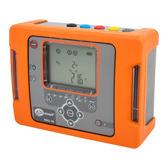
OPERATING MANUAL EARTH GROUND RESISTANCE METER MRU-30 SONEL S. A. Świdnica, Poland SONEL TEST & MEASUREMENT Santa Clara, CA 95054 Version 1.03 April 2017... - Page 4 The Sonel MRU-30 meter is an easy-to-use instrument that is designed for the safe measurement of earth ground resistance. The MRU-30 uses established methods of earth ground resistance measurements such as 3-pole, 4- pole, and 3-pole with auxiliary clamp. Additionally the MRU-30 employs the two clamp method of measurement without the use of auxiliary test rods when rods can't be used in some situations.
-
Page 5: Table Of Contents
POWER SUPPLY OF THE METER ..............39 ............40 ONITORING THE POWER SUPPLY VOLTAGE ..........40 HARGING THE RECHARGEABLE BATTERY PACK ..........41 ENERAL PRINCIPLES OF USING BATTERIES CLEANING AND MAINTENANCE ..............42 STORAGE ......................42 MRU-30 OPERATING MANUAL version 1.03... - Page 6 (3P + clamp) .... 46 12.2.6 Additional uncertainties in accordance with IEC 61557-5 (3p, 4p) ... 47 ACCESSORIES ..................... 47 13.1 ................... 47 TANDARD ACCESSORIES 13.2 ................. 47 DDITIONAL ACCESSORIES MANUFACTURER ....................48 MRU-30 OPERATING MANUAL version 1.03...
-
Page 7: Safety
The MRU-30 meter has been designed for measurements of earth/ground connections, equipoten- tial bonding, and ground resistivity. Any application or use of the MRU-30 that differs from those specified in this manual may result in damage to the meter and constitute a source of danger to the user. -
Page 8: Turning The Meter On And Activating The Screen Backlight
– 50 Hz or 60 Hz (50 Hz is set as default). Use the buttons to show bEEP on the screen to allow turning audio sound on or off. MRU-30 OPERATING MANUAL version 1.03... - Page 9 (Auto-OFF): The choices are 300 s, 600 s, 900 s or none (dashes - Auto-OFF is disa- bled). Use the buttons to show the diSt screen to allow the unit of length to be selected: MRU-30 OPERATING MANUAL version 1.03...
- Page 10 After changing the parameters, to exit the SETUP menu, either: Press the ENTER button to memorize set- tings (not applicable for the Update screen) Or: press the ESC button to go to the meas- urement screen without confirming changes. MRU-30 OPERATING MANUAL version 1.03...
-
Page 11: Measurements
Before starting the measurement in these modes: 2P, 3P, 4P, 3P+C, R cont before pressing the START button the MRU-30 monitors the voltage present on the measurement terminals (between E and other sockets) and displays the value of the interfering voltage on the screen. - Page 12 50 V. Press ENTER to save the setting or press ESC to exit without saving. Connect the test leads according to the drawing. The meter is ready for measurement. Press START to begin measurement. MRU-30 OPERATING MANUAL version 1.03...
-
Page 13: Measurement 3P
4.3 Measurement 3P The basic type of earth ground resistance measurement is the three-pole measurement. Disconnect the earth electrode object of test. << >> Use the buttons to select the measurement mode: 3P. The LED MRU-30 OPERATING MANUAL version 1.03... - Page 14 Connect the earth electrode object of test to the E terminal of the meter. All 3 electrodes should be aligned in a straight line. The meter is ready for measurement. Press START to begin measurement. MRU-30 OPERATING MANUAL version 1.03...
- Page 15 A solution is to perform, in accordance with the formulae specified in section 12.2, calculations which will take into account the influence of the measurement conditions. It is also possible to improve the contact of the electrode with the ground by moistening the area where the MRU-30 OPERATING MANUAL version 1.03...
-
Page 16: Measurement Method
It eliminates the influence of the test lead resistances. To evaluate the resistivity of the ground it is recommended to use the dedicated measurement function in section 4.9. Disconnect the earth electrode object of test. MRU-30 OPERATING MANUAL version 1.03... - Page 17 Use the buttons to select the measurement voltage of 25 V or 50 V. Press ENTER to save the setting or press ESC to exit without saving. Connect the test leads according to this diagram: MRU-30 OPERATING MANUAL version 1.03...
- Page 18 – resistance of current electrode - resistance of voltage electrode ER – additional uncertainty caused by the re- sistance of the electrodes – interfering (noise) voltage. The result is displayed for 20 seconds. Press ENTER to display again. MRU-30 OPERATING MANUAL version 1.03...
- Page 19 ‘NOISE!’ and xxV, >24V, Where xx is the value of the interfering voltage. The volt- age on the measurement terminals is > 24 V, but < 40 V. ‘NOISE!’ and The measurement cannot proceed. MRU-30 OPERATING MANUAL version 1.03...
-
Page 20: Clamp Measurement Method
Use the buttons to set the measurement voltage value to 25 V or 50 Press ENTER to save the setting or press ESC to exit without saving. Connect test leads according to this diagram: MRU-30 OPERATING MANUAL version 1.03... - Page 21 All 3 electrodes should be aligned in a straight line. The meter is ready for measurement. Use the buttons to toggle be- tween the measurements: – interfering (noise) voltage, – leakage current measured by the clamp Press START to begin measurement. MRU-30 OPERATING MANUAL version 1.03...
- Page 22 Such a situation can occur if the earth electrode is properly made and the upper layer of the ground is both dry, and has low conductivity. Then the MRU-30 OPERATING MANUAL version 1.03...
-
Page 23: Two-Clamp Measurement Method
4.6 Two-clamp Measurement method The two-clamp measurement is employed when there is no possibility of using earth ground elec- trodes or ground-rods. NOTE! The two-clamp method is used specifically only in the case of multiple earth ground systems. MRU-30 OPERATING MANUAL version 1.03... - Page 24 Attach the transmission clamp and the measurement clamp around the tested earth electrode object of test at least 30cm / 12 in from each other. The meter is ready for measurement. Press START to begin measurement. MRU-30 OPERATING MANUAL version 1.03...
- Page 25 The measurement cannot proceed. xxV, >40V and a Where xx is the value of interfering voltage. The voltage continuous tone , on the measurement points is > 40 V. The measurement cannot proceed. ‘NOISE!’ and MRU-30 OPERATING MANUAL version 1.03...
-
Page 26: Calibration Of The Measurement Clamp C-3
Flashing CAL message indicates meter is ready for the clamp cali- bration procedure. Connect the 'E' and the 'H' termi- nals together with a test lead and put the clamp around the lead. Press START button. MRU-30 OPERATING MANUAL version 1.03... -
Page 27: Measurement Of Earth Connection And Equipotential Bonding (200Ma)
R The LED CONT 200mA. is illuminated. The meter is now in the state of measuring interfering noise voltage between the measurement terminals. Connect the test leads according to this diagram: MRU-30 OPERATING MANUAL version 1.03... - Page 28 The meter is ready for measurement. Press START to begin measurement. After the measurement completes view the values of resistance and the interfering voltage on the screen. The result is displayed for 20 seconds. Press ENTER to display again. MRU-30 OPERATING MANUAL version 1.03...
- Page 29 The flashing AUTO-ZERO mes- sage indicates the test leads cali- bration procedure is ready to begin. Connect the test leads according to this diagram: Short-circuit the test leads connected to the ‘E’ and ‘S’ terminals. MRU-30 OPERATING MANUAL version 1.03...
-
Page 30: Earth Resistivity Measurement
Use the buttons to set the dis- tance between the electrodes . From 1 to 50 m, in 1 m steps, or from 1 to 150 ft, in 1 ft steps. MRU-30 OPERATING MANUAL version 1.03... - Page 31 Connect the voltage electrode to the S socket of the meter, Connect the voltage electrode to the ES socket of the meter, Connect the current electrode to the E socket of the meter. The meter is ready for measurement. Press START to begin measurement. MRU-30 OPERATING MANUAL version 1.03...
- Page 32 Also, check the test leads and make sure the insulation is not damaged and the contacts of the test leads, banana plugs, and probes are not corroded or loose. In most cases measurements will be satisfactory but be conscious of the uncertainty the measurement can be burdened with. MRU-30 OPERATING MANUAL version 1.03...
-
Page 33: Memory Of Measurement Results
Memory of measurement results Measurements can be stored in memory. The MRU-30 has a memory divided into 10 banks of 99 cells each. Each memory cell can store all measurement results of individual tests. Measurement results are stored in a memory cell with a selected number and selected memory bank. -
Page 34: Storing The Measurement Results In The Memory
When the cell number is flashing, use the buttons to select the desired number of the cell. Press the SET/SEL button. The bank number will be flashing. Use the buttons to select the de- sired number of the bank. MRU-30 OPERATING MANUAL version 1.03... -
Page 35: Viewing Memory Data
All results for a given measuring function and preset measurement settings are stored in the memory. 5.2 Viewing memory data << >> Use the buttons to select the memory function: MEM. the LED Illuminated. Use the buttons to preview any test results stored in a selected cell. MRU-30 OPERATING MANUAL version 1.03... -
Page 36: Deleting Memory Data
You can delete the entire memory or individual cells or banks. 5.3.1 Deleting cell data << >> Use the buttons to select the memory function: MEM. The LED is illuminated. Set the cell number to be deleted by using the buttons. Press ENTER. MRU-30 OPERATING MANUAL version 1.03... - Page 37 Press ENTER button again to delete the contents of the selected cell. After deleting the cell, the meter beeps three times. Press ESC to cancel and return to memory browsing. The contents of the cell have been deleted. MRU-30 OPERATING MANUAL version 1.03...
-
Page 38: Deleting Bank Data
The cell number will flash. Set the cell number to ‘- -’ (before 01) by pressing the but- ton. Then the message is displayed. Press ENTER. symbol and dEL ConF ? mes- sages appear. MRU-30 OPERATING MANUAL version 1.03... -
Page 39: Deleting The Whole Memory
Press the SET/SEL button until the bank number flashes. Set the bank number to ‘-’ (before 0) by pressing the but- ton. The bank number will change to ‘-’ Then the message is displayed. MRU-30 OPERATING MANUAL version 1.03... -
Page 40: Data Transmission
Data transmission 6.1 Computer connection accessories To operate the meter with a computer, a USB cable and Sonel Reader software is required. If these accessories have not been purchased along with the meter they are available from the Sonel or an authorized Sonel distributor. -
Page 41: Data Transmission Through Usb Port
Connect the USB cable from the USB meter socket to the USB port of the computer. The meter will display the message PC: Start the Sonel Reader software for communicating with the meter. Firmware update In accordance with the guidelines of Section 3 of this manual, enter the meter’s firmware update mode: UPdt. -
Page 42: Power Supply Of The Meter
8.2 Charging the rechargeable battery pack CAUTION! The MRU-30 meter is powered from a SONEL NiMH 9.6 V battery pack. It can only be replaced by Sonel or an authorized Sonel service center. The internal battery charger is powered by an external 12V Sonel AC power supply adapter. The device may be also powered from a 12V car accessory socket. -
Page 43: General Principles Of Using Ni-Mh Batteries
Do not charge or use batteries in extreme temperatures. Extreme temperatures reduce the lifetime of batteries. Avoid using devices powered from Ni-MH batteries in very hot environments. The nominal working temperature must be observed. MRU-30 OPERATING MANUAL version 1.03... -
Page 44: Cleaning And Maintenance
Only use the maintenance methods described in this manual. The outside of the MRU-30 meter may be cleaned with a soft, damp cloth using all-purpose deter- gents. Do not use any solvents or cleaning agents or abrasives which might scratch the case. -
Page 45: Technical Specifications
2000 Ω to 9999 Ω 1 Ω ±8% m.v. Measurement of the auxiliary electrode resistance Range Resolution Basic uncertainty 0 to 999 Ω 1Ω ±(5% (R 1.00 to 9.99 kΩ 0.01kΩ 8 digits) 10.0 to 19.9 kΩ 0.1kΩ MRU-30 OPERATING MANUAL version 1.03... - Page 46 4P measurement but not less than ±1 digit. 20.0 to 99.9 kΩm 0.1 kΩm 100 to 999 kΩm 1 kΩm distance between measurement probes (L): 1 to 50 m, or 1 to 150 ft MRU-30 OPERATING MANUAL version 1.03...
-
Page 47: Additional Data
Maximum resistance of measurement electrodes ..............20 k Signaling of insufficient clamp current ................≤0.5 mA m) Power supply ..........rechargeable batteries type SONEL NiMH 9.6 V 2 Ah n) AC adapter for the battery charger ............100 V to 240 V, 50/60 Hz ........ -
Page 48: Functions 3P, 4P, 3P + Clamp, Ρ
3P+clamp The MRU-30 meter may perform a measurement, if the value of the interference current does not exceed 3 A rms and the frequency complies with the value set in the MENU. -
Page 49: Additional Uncertainties In Accordance With Iec 61557-5 (3P, 4P)
Power supply adaptor Z7 – WAZASZ7 Calibration certificate Operating manual Sonel CD with software and drivers 13.2 Additional accessories Optional items available from Sonel or authorized Sonel distributors: WASONG80 WACEGN1BB Earth contact test probe (rod); 80 cm Transmitting clamp N-1 MRU-30 OPERATING MANUAL version 1.03... -
Page 50: Manufacturer
Santa Clara, Ca 95054 USA tel. +1 (408) 898 2215 fax +1 (408) 988 4869 E-mail: testsupport@soneltest.com Web: www.soneltest.com Attention: Service and repairs must be carried out only by Sonel or an authorized Sonel service center. MRU-30 OPERATING MANUAL version 1.03...
Need help?
Do you have a question about the MRU-30 and is the answer not in the manual?
Questions and answers