
Related Manuals for Allen-Bradley The PowerFlex 755 On-Machine


Summary of Contents for Allen-Bradley The PowerFlex 755 On-Machine
- Page 1 PowerFlex 755 On-Machine Drive Bulletin Number 26G User Manual Original Instructions...
- Page 2 PowerFlex 755 On-Machine Drive User Manual Important User Information Read this document and the documents listed in the additional resources section about installation, configuration, and operation of this equipment before you install, configure, operate, or maintain this product. Users are required to familiarize themselves with installation and wiring instructions in addition to requirements of all applicable codes, laws, and standards.
-
Page 3: Table Of Contents
Table of Contents Preface Summary of Changes ......... . . 7 Conventions Used in This Manual . - Page 4 Table of Contents 24V DC Control Power Receptacle ......44 Make Connections ..........44 Receptacle Configurations on the Gland Plate .
- Page 5 Table of Contents Create a Safety Program to Control the Drive Safety Circuits........135 Save and Download the Project .
- Page 6 Table of Contents Troubleshooting Going Online....... . 185 View Adapter Status By Using Parameters ....185 Access the Adapter Web Pages.
-
Page 7: Summary Of Changes
Preface This publication provides basic information to install, connect, and maintain the PowerFlex® 755 On-Machine™ drives. For information on programming, troubleshooting, safety application requirements, and EtherNet/IP networks, see the publications that are listed in Additional Resources on page This manual is intended for qualified personnel. You must be able to program and operate adjustable frequency AC drives. -
Page 8: Additional Resources
Preface Additional Resources The following publications provide general product information. Resource Description Motor Protection Circuit Breaker and Motor Circuit Provides product selection and specification information for Protector Specifications, publication 140-TD005 Bulletin 140MP/MT motor protection circuit breakers and motor circuit protectors. Bulletin 140G Flexible Cable Oper Mech-140G-G, Installation instruction for Flex Cable Operator for 140G-G 140G-H, 140G-I, 140G-J, 140G-K,... - Page 9 Preface Resource Description PowerFlex 755 Drive Embedded EtherNet/IP This manual provides information about the EtherNet/IP Adapter User Manual, publication 750COM-UM001 adapter that is embedded on the main control board in PowerFlex® 755 drives, and how to use it for network communication.
- Page 10 Preface The following publications provide maintenance information. Resource Description 1321-M055 Common Mode Choke, publication Provides instructions on replacing a common mode choke in a 1321-IN002 PowerFlex 750-Series frame 1…7 drive. PowerFlex 750-Series EMC Cores - Frames 1...5 Provides instructions on replacing EMC Cores in PowerFlex Installation Instructions, publication 750-IN007 750-Series frame 1…5 drives.
-
Page 11: Getting Started
Chapter Getting Started System Overview The PowerFlex® 755 On-Machine™ Drive is a small footprint UL Type 12 / IP66 (indoor use only) enclosure. It offers several configurations for encoder feedback, Safe Torque Off, and the Network Integrated Safety Function. The product also includes quick-connect connections for: I/O, power, motor, safety, encoder feedback, positioning, communication, and brake connectors on the bottom gland plate. -
Page 12: Data Nameplate And Ul Listing
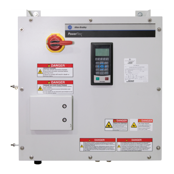
Chapter 1 Getting Started Hoist Lifting Mounting Hole (x2) Hole (x2) Main Power Circuit Breaker Handle UL Label Hand Lifting Data Nameplate Handles (x2) Auxiliary Circuit Breaker Door Grounding Stud Collar Stud for (PE Ground) Resistor Mounting Plate (x4) Mounting Hole (x2) Receptacles Data Nameplate and UL Listing... -
Page 13: System Configuration Example
Getting Started Chapter 1 An example of the data nameplate follows. The information that is listed here is only an example and should not be used for reference. Your nameplate is specific to your product. Nameplate : Specifications and Custom Catalog Number r epresenting options installed at factory. - Page 14 Extension Receptacle (SpeedTEC ready) (only for servo motors) 280-PWRM35* or Three-Phase power patchcord cable with integral female or male connector on 280-PWRM29* each end (only for induction motors) — Induction motor or Allen-Bradley® servo motor — ArmorStart controller — PowerFlex 755 On-Machine Drive 1732ES-IB8X0BV4 or ArmorBlock®...
-
Page 15: Armorconnect Power Media
Getting Started Chapter 1 ArmorConnect Power Media The ArmorConnect power media offers both three-phase and control power ® cable systems. These include patchcords, receptacles, tees, reducers, and accessories to be used with the drive. These cable system components create a quick connection to the drive, reducing installation time. -
Page 16: Catalog Number Explanation
24V DC auxiliary power input, mini 4-pin male (1) Options SB and B2 are for use with AC induction motors. Input Type Safety Option Module - Slot 6 Option B3 is for use with Allen-Bradley MPM and MPL servo Code Description Code Type motors. -
Page 17: Prepare For Installation
Chapter Prepare for Installation Precautions ATTENTION: This manual is intended for qualified service personnel responsible for installing and servicing these devices. You must have previous experience with, and a basic understanding of: electrical terminology, configuration procedures, required equipment, and safety precautions. - Page 18 Chapter 2 Prepare for Installation WARNING: Circumstances that can cause an explosion may exist, which may lead to personal injury or death, property damage, or economic loss. • Tripping of the instantaneous-trip circuit breaker is an indication that a fault current has been interrupted.
-
Page 19: Electrical Safety Considerations
Prepare for Installation Chapter 2 Electrical Safety Considerations IMPORTANT To avoid electrolytic corrosion on the external earth terminal, avoid spraying moisture directly on the terminal. When used in wash-down environments, apply a sealant or other corrosion inhibitor on the external ground terminal to minimize any negative effects of galvanic or electro-chemical corrosion. -
Page 20: Environment
Chapter 2 Prepare for Installation Prevent Electrostatic Discharge ATTENTION: This drive contains ESD (Electrostatic Discharge) sensitive parts and assemblies. Static control precautions are required when you install, test, service, or repair this assembly. Component damage can result if ESD control procedures are not followed. If you are not familiar with static control procedures, see an applicable ESD protection handbook. -
Page 21: Electromagnetic Compatibility (Emc)
Prepare for Installation Chapter 2 While the drive is intended for installation in factory floor environments of industrial establishments, the following must be considered when locating the drive in the application: • Cables that include control voltage cables, for example, 24V DC, safety, and communications, are not to be exposed to operator or building traffic on a continuous basis. -
Page 22: Wiring
Chapter 2 Prepare for Installation • When using a shielded motor cable, the drain wire must be bonded to chassis ground at the motor. The recommended motor connection must use a shielded concentric connector. This connection provides 360 ° shielding. Wiring Wire in an industrial control application can be divided into three groups: power, control, and signal. -
Page 23: Circuit Protection
Prepare for Installation Chapter 2 ATTENTION: The PowerFlex 755 drive contains protective Metal Oxide Varistors (MOVs) that are referenced to a ground. These devices must not be disconnected or installed on an ungrounded and high resistive distribution system. Failure to do so may lead to personal injury or death, property damage, or economic loss. -
Page 24: Short-Circuit Current Rating (Sccr)
Chapter 2 Prepare for Installation Figure 2 - Feeder Circuit Protection U (T1) R (L1) V (T2) S (L2) Maximum W (T3) T (L3) 65,000 A SCCR Shielded Motor Cable SHLD Exposed Structure and/or Building Steel Exposed Structure and/or Building Steel 1. -
Page 25: Branch Circuit Protection Requirements For Three-Phase Power Media
Prepare for Installation Chapter 2 The mechanical brake circuit breaker and the control power circuit breaker are located under the auxiliary circuit breaker door and are provided power by Receptacles CP (24V DC auxiliary power), CPBR (24V DC brake option B2 and B3), and L123 (source brake option SB). -
Page 26: Minimum Mounting Clearances
Chapter 2 Prepare for Installation Circuit Breaker: Suitable for use on a circuit capable of delivering not more than 65,000 RMS symmetrical amperes at 480V AC maximum, when mostly protected by a catalog number 140G-H6C3-C60 circuit breaker with a maximum ampere rating of 60 A and an interrupting rating not less than of 65,000 RMS symmetrical amperes, 480V AC. -
Page 27: Dimensions
Prepare for Installation Chapter 2 Dimensions The approximate dimensions are shown in millimeters (inches). Dimensions are not intended to be used for installation purposes. All dimensions are approximate. Front View Left View Back View Bottom View Drive Dimensions Millimeters 711.2 391.9 260.5 527.0... -
Page 28: Receive, Unpack, And Inspect The Drive
Chapter 2 Prepare for Installation Receive, Unpack, and Inspect Upon delivery, follow these steps to unpack and inspect the drive. The carton label appears similar to the example below and contains basic product and the Drive packaging information. Receiving Standard drive enclosures are shipped horizontal. Each unit or shipping section is bolted to a wooden shipping skid with removable shipping cleats and is covered an anti-corrosion type of plastic wrap. - Page 29 • Language labels • Product Information, publication 750-PC004 • An envelope containing installation instructions for components TIP To order additional copies of the electrical schematics, contact your local Allen-Bradley distributor or Rockwell Automation sales representative. Rockwell Automation Publication 750-UM006C-EN-P - March 2022...
-
Page 30: Unpack And Inspect
Note on the delivery receipt that the equipment is damaged. b. Contact the carrier that delivered the shipment and the authorized Allen-Bradley® distributor. The carrier may schedule a freight inspection or will waive their right to inspect. If they waive their right to inspect, obtain the written waiver. -
Page 31: Lift And Transport The Drive
Prepare for Installation Chapter 2 Lift and Transport the Drive All lifting equipment and components (hooks, bolts, lifts, slings, chains, and so on) must be properly sized and rated to lift and hold the weight of the drive. Read these precautions before attempting to lift a drive. ATTENTION: All equipment and hardware that is used to lift the drive must be properly sized and rated to lift and hold the weight of the drive safely. - Page 32 Chapter 2 Prepare for Installation Mechanical Lifting Handle (one left / one right) Dimensions are in millimeters and (inches). Hand-hold Lifting Handle > 60 (one left / one right) > 305 (12.00) (24.00) 3. To reduce tension on the rigging and compression on the structural angle, verify that the angle between the straps or cables and horizontal plane is greater than 60°.
-
Page 33: Two-Person Lifting
Prepare for Installation Chapter 2 4. Slowly lift the drive from the shipping container and transport the drive to the installation location. ATTENTION: Risk of equipment damage exists. Interconnect receptacles protrude from the bottom of the drive. Be sure that the drive does not crush or apply pressure to the receptacles when placed on a flat surface or installed. -
Page 34: Apply Labels To The Drive
Chapter 2 Prepare for Installation Apply Labels to the Drive The multiple language labels for the product are shipped with the product and must be attached to the drive. The English and French language labels should not be removed or covered up. Any additional labels must be added on a bare surface. -
Page 35: Install The Drive
Chapter Install the Drive ATTENTION: The following information is merely a guide for proper installation. Rockwell Automation cannot assume responsibility for the compliance or the noncompliance to any code, national, local, or otherwise for the proper installation of this drive or associated equipment. A hazard of personal injury and/or equipment damage exists if codes are ignored during installation. -
Page 36: Ground The Drive
Chapter 3 Install the Drive Ground the Drive ATTENTION: A hazard of personal injury and equipment damage exists. A minimum of 10 AWG should be used for the solid earth-grounding-system. To properly ground the package drive, connect the Safety Ground-PE terminal to the power-distribution earth-grounding-system through a ground or low impedance connections. -
Page 37: Grounding Pe Or Ground
Install the Drive Chapter 3 appropriate gauge. Most equipment has specific provisions to connect a safety ground or PE (protective earth) directly to it. IMPORTANT The safety ground (PE), must be connected to the power-distribution earth- grounding-system. Some codes may require redundant ground paths and periodic examination of connection integrity. -
Page 38: Select Cables
Chapter 3 Install the Drive IMPORTANT For compatibility, the motor cable connector that is selected must provide good 360° contact and low transfer impedance from the shield or armor of the cable to the conduit entry plate at both the motor and the drive, for electrical bonding. - Page 39 Install the Drive Chapter 3 Table 4 - Cable Descriptions and Receptacle Information Receptacle Receptacle Description Recommended Cable Description Image Abbreviation Interface Cable / Connector L123 Input Power Receptacle, 280-PWRM35A-M* ArmorConnect Power Media - Trunk IN1, M35, 4-pin Cable, IP67, UL 4/12, NEMA 6P, Straight Female to Straight Male Patchcord, 10 AWG 280-PWRM35E-M*...
- Page 40 Chapter 3 Install the Drive Table 4 - Cable Descriptions and Receptacle Information (continued) Receptacle Receptacle Description Recommended Cable Description Image Abbreviation Interface Cable / Connector CPBR 24V DC Brake Power 889N-F4AFNM-* Patchcord: Mini/Mini Plus, Female, Receptacle, mini, 4-pin Straight, 4-Pin, PVC Cable, Yellow, Unshielded, IEC Color Coded, Mini, Male, Straight, 16 AWG 889N-F4AENM-D*...
- Page 41 Install the Drive Chapter 3 Table 4 - Cable Descriptions and Receptacle Information (continued) Receptacle Receptacle Description Recommended Cable Description Image Abbreviation Interface Cable / Connector DBRT Brake Resistor 889D-F4ACDM-* Patchcord: DC Micro (M12), Female, Thermostat Temperature Straight, 4-Pin, PVC Cable, Yellow, Receptacle, micro, 4-pin Unshielded, IEC Color Coded, DC Mic, Male, Straight...
- Page 42 Chapter 3 Install the Drive Table 4 - Cable Descriptions and Receptacle Information (continued) Receptacle Receptacle Description Recommended Cable Description Image Abbreviation Interface Cable / Connector S0 Network Safety 889D-M5AC-* DC Micro (M12), Female, Straight, 5- Receptacle, C, micro, 5- Pin, PVC Cable, Yellow, Unshielded, IEC (S4 safety with pin, female...
- Page 43 Install the Drive Chapter 3 Table 4 - Cable Descriptions and Receptacle Information (continued) Receptacle Receptacle Description Recommended Cable Description Image Abbreviation Interface Cable / Connector ENC0 Incremental Encoder Receptacle, M23, 12-pin, HIPSC HIP Encoder Receptacle, M23,12-pin, E42 SSISC SSI SC Rotary Encoder Receptacle, M23,12-pin, DENC0 Dual Incremental Encoder...
-
Page 44: Control Power
Chapter 3 Install the Drive Control Power The drive uses 24V DC control power for communications and I/O. It uses switched power supplies for the outputs. Unswitched power supplies provide power to Logix and sensor inputs. For more information about the control power pin out information, see Receptacle Connections on page 24V DC Control Power Receptacle... - Page 45 Install the Drive Chapter 3 Figure 3 - Maximum Possible Receptacle Details Induction Motor 24V DC Brake (< 15.4 amps) Figure 4 - Maximum Possible Receptacle Details Induction Motor 24V DC Brake (22 amps) Figure 5 - Maximum Possible Receptacle Details Induction Motor Source Brake (< 15.4 amps) Rockwell Automation Publication 750-UM006C-EN-P - March 2022...
- Page 46 Chapter 3 Install the Drive Figure 6 - Maximum Possible Receptacle Details Induction Motor Source Brake (22 amps) Figure 7 - Maximum Possible Receptacle Details Servo Motor 24V DC Brake (< 14 amps) Figure 8 - Maximum Possible Receptacle Details Servo Motor 24V DC Brake (22 amps) Rockwell Automation Publication 750-UM006C-EN-P - March 2022...
-
Page 47: Receptacle Connections
Table 5 - Drive Gland Plate Abbreviation Definitions Terminal Description Terminal Description Designations Designations L123 Input Power CFBM Allen-Bradley® Servo Bulk Head Hiperface Encoder T123 Output Power CPBM Allen-Bradley Servo Motor Power and Brake Dynamic Brake ENCO M23 Incremental Encoder... - Page 48 Cosine (+) Ground I/O-DI2 Cosine (–) Not Used Sine (+) [CPBM] Allen-Bradley Servo Motor (14 amps or less) Power Output [P1] Digital Input, M12, DC micro Sine (–) (motor connection) and mechanical brake (24V DC) Function Channel X data (–)
-
Page 49: Configure And Start Up The Drive
Chapter Configure and Start Up the Drive This chapter includes information to establish communication with the drive via the embedded EtherNet/IP adapter, view adapter status via parameters, configure the basic startup parameters, and how to set or clear a fault action via drive parameters. -
Page 50: Set The Network Ip Address Of The 1783-Etap
Chapter 4 Configure and Start Up the Drive Volts (C) S4 Integrated Safe Horizontal / Speed Monitoring with Vertical Source Brake Amps Mechanical Motor (N) None Max Velocity Brake Data Port Assignment # Motor Poles Current Position Loop Amps Speed Loop Motor Polarity Voltage 24V DC or... -
Page 51: Ethernet/Ip Adapter
Configure and Start Up the Drive Chapter 4 Configure the PowerFlex 755 You must use the HIM to configure the adapter IP address. The embedded EtherNet/IP adapter stores parameters and other information in nonvolatile Drive Embedded EtherNet/IP storage (NVS) memory. Access the adapter by using the HIM to view and edit Adapter these parameters. - Page 52 Chapter 4 Configure and Start Up the Drive Figure 9 - Circuit Breaker Identification 1. 400/480V AC rotary power for main circuit breaker (140G-G6C3-C30-AJ). 2. 24V DC mechanical brake circuit breaker (1489-M2D040) is shown on the enclosure. The 400/480V AC source mechanical brake circuit breaker (140M-C2E-B25/140MT-C3E-B25) is shown on the left. 3.
-
Page 53: Access Parameters
Configure and Start Up the Drive Chapter 4 Use the PowerFlex 20-HIM-C6S HIM to Access Parameters The drive has an enhanced drive HIM, and it can be used to access parameters in the adapter. 1. Verify that all cables are connected properly to the drive (see Make Connections on page 44). - Page 54 Chapter 4 Configure and Start Up the Drive Disable the BOOTP Feature or Change the Source for the Node Address 1. Set the value of 13:36 [BOOTP] to 0 (Disabled). Stopped AUTO 0.00 Hz Edit BOOTP Disabled 0 << 1 ...
- Page 55 Configure and Start Up the Drive Chapter 4 Set the Gateway Address 1. Verify 13:36 [BOOTP] is set to 0 (Disabled). 2. Set the value of 13:46 [Gateway Cfg 1] … 13:49 [Gateway Cfg 4] to the IP address of the gateway device. Default = 0.0.0.0 255.255.255.2 Stopped AUTO...
-
Page 56: Startup Introduction
Chapter 4 Configure and Start Up the Drive Startup Introduction The human interface module (HIM) displays the general start-up menu by default upon initial power up of the drive. To navigate to the start-up menu after the initial power up of the drive, press the (Folders) key. -
Page 57: Add-On Profiles
Configure and Start Up the Drive Chapter 4 Add-on Profiles There are separate Add-on Profiles for the Logix Designer application for each of these Modes of control, along with the safety option module used in the drive. See the On-Machine drive Catalog Number Explanation on page 16 identify which safety option module is installed in your drive as indicated in Data Nameplate and UL Listing on page 12... -
Page 58: Choose Startup Mode
Chapter 4 Configure and Start Up the Drive IMPORTANT Before you can configure your drive in the Logix Designer application, you must have a controller project with an EtherNet/IP network connection configured and Time Sync enabled. See the documentation for your controller for information on configuring those products. -
Page 59: Drive Startup - I/O Mode
Configure and Start Up the Drive Chapter 4 Integrated Motion Mode Integrated Motion mode uses Integrated Motion on EtherNet/IP technology with Studio 5000 environment software. Version 31.00 of Studio 5000 environment and later with an L8 processor is required with Network Integrated Safety Function (S4) option modules used in the On-Machine drive. -
Page 60: Add The Powerflex 755 Drive To Your Project
Chapter 4 Configure and Start Up the Drive TIP The procedure is written for the Network-Integrated Safe Torque Off (S3) option module. The same procedure, with slight modifications, works for both Network-Integrated Safety Function (SSM) and Network-Integrated Safety Function with Brake Control (S4) option modules. TIP Variations to the procedure for the SSM or S4 option modules, will appear as tips throughout the procedure. - Page 61 Configure and Start Up the Drive Chapter 4 3. Right-click the Ethernet network in the Controller Organizer and select New Module to add the PowerFlex 755 drive to the EtherNet/IP network. 4. In the Select Module Type dialog box, type PowerFlex 755. 5.
- Page 62 Chapter 4 Configure and Start Up the Drive 6. On the Identity page of the Device Definition dialog box, type a Name, Description (optional), and the IP address of the drive. In this example, we use PowerFlex 755_PTP_Turntable and an IP address of 192.168.1.56.
-
Page 63: Update The Module Properties
Configure and Start Up the Drive Chapter 4 Update the Module Properties There are three ways to add the drive data that is required to populate the module properties. • Import a Template File on page 63 that is loaded on your computer •... - Page 64 Chapter 4 Configure and Start Up the Drive 2. Select the drive IP address that you want to import into the Logix PowerFlex 755 Device Definition and click Continue. While the Logix Designer application imports the drive information, it shows a status bar, which indicates the progress. 3.
- Page 65 Configure and Start Up the Drive Chapter 4 3. Select the firmware levels. 4. Choose the Peripherals page to add the modules identified in the Data Nameplate and UL Listing on page 12 section. See Catalog Number Explanation on page 16 for more information.
-
Page 66: Verify Drive Data
Chapter 4 Configure and Start Up the Drive 5. Click OK. 6. See Verify Drive Data on page 66 to confirm that the data was properly entered. Verify Drive Data 1. After the data is entered, review the Overview page to verify that the data matches the drive being commissioned. -
Page 67: Choose Integrated Or Hard-Wired Safety
Configure and Start Up the Drive Chapter 4 Choose Integrated or Hard-wired Safety When a safety option module is installed in the PowerFlex 755 On-Machine Drive, you must decide if you want to use integrated (network) safety or hardware-based (hard-wired) safety. - Page 68 Chapter 4 Configure and Start Up the Drive • If you want to use Integrated Safety over the network, the connection type must be Standard and Safety. TIP For SSM and S4, continue reading. • If you want to use Network-Integrated Safety Function (SSM) or Network-Integrated Safety Function with Brake Control (S4), the connection type must be Standard and Safety (20-750-S4).
-
Page 69: Safety Configuration For Ssm And S4
Configure and Start Up the Drive Chapter 4 5. Then click Yes to proceed. Safety Configuration for SSM and S4 TIP The steps that follow are a result of the sample configuration that was selected. Refer to PowerFlex 755/755T Integrated Safety Functions Option Module, publication 750-UM005 for additional... - Page 70 Chapter 4 Configure and Start Up the Drive 1. Review and verify that information on the drive overview page. 2. On the Overview page, select Safety Configuration. 3. Select Actions. Rockwell Automation Publication 750-UM006C-EN-P - March 2022...
- Page 71 Configure and Start Up the Drive Chapter 4 4. Change Actions to determine how the system should respond if communication to the device is disrupted. 5. Select the STO tab, review graph. 6. Select the SS1 tab, the information here can be setup in the drive or in the PLC.
-
Page 72: Configure The Drive Parameters
Chapter 4 Configure and Start Up the Drive If you want a fault to occur in the system if a maximum speed or maximum acceleration is exceeded, set values in the right column. This is not safety related, it only pertains to operational limits.. 9. - Page 73 Configure and Start Up the Drive Chapter 4 each step in the Startup Wizard, click Next to accept the configuration and move to the next step TIP The system is currently offline from both the Logix Designer application and the drive. 1.
- Page 74 Chapter 4 Configure and Start Up the Drive This determines how the drive responds if it looses its EtherNet/IP connection to the Logix controller. Fault while running or when idle is the default configuration. 5. On the Motor Control step, select: Motor Control Mode, Speed Units (RPM is standard), and Feedback Encoders that are used for the Speed and Position feedback (these typically match).
- Page 75 Configure and Start Up the Drive Chapter 4 6. On the Motor Data step, enter the Motor Nameplate data. Click Next. This information is found in the Prepare for Initial Drive Startup on page 49 table. 7. On the Stop Mode step, enter the desired stop/brake mode along with the dynamic brake resistor data collected before startup.
- Page 76 Chapter 4 Configure and Start Up the Drive TIP In the PowerFlex 750-Series Programming manual, publication 750-PM001, P385 max is 100,000,000. 2million is used here as an example. In the On- Machine Drive, DBRT provides the normally-closed thermostat feedback that is used to protect the Db resistor. 8.
- Page 77 Configure and Start Up the Drive Chapter 4 If the drive is being used for positioning, the maximum speeds should be set +/- 10% higher than the highest commanded move speed. This allows the position loop to close out position errors. 10.
- Page 78 Chapter 4 Configure and Start Up the Drive TIP If you want the PLC to control the speed reference, change to the Port 0: Parameter 13 [EtherNet/IP]. 12. Click Next. 13. On the Torque Reference step, leave the values at their defaults for all speed and position-based drives.
- Page 79 Configure and Start Up the Drive Chapter 4 14. If the drive is used as a Position and point-to-point (PTP) regulated drive, set the parameters for the desired performance on the Position PTP Reference step. Click Next. TIP Refer to Prepare for Initial Drive Startup for information.
- Page 80 Chapter 4 Configure and Start Up the Drive These do not need to be set if all control actions are coming from the Logix controller. The Logix controller command control word contains start/stop, run/jog, forward/reverse, and so on. These inputs can be used if one of the four I/O points (P0 and P1) on the drive are wired and a desired function must be configured.
- Page 81 Configure and Start Up the Drive Chapter 4 You could also not assign it to this function, but choose to read its status by using the Logix controller via Datalink out, and determine what action to take when it opens. This action could be to shut down, complete machine index, then shut down, and so on.
- Page 82 Chapter 4 Configure and Start Up the Drive The electrical schematics show that both the Digital Relay Output 0 and the Transistor Output 0 are wired in parallel to the brake coil. This lets the drive sequence the brake when running, or lets the Logix controller release the brake when not running (typically used during testing).
- Page 83 Configure and Start Up the Drive Chapter 4 • Rockwell Automation recommends that you configure the Digital Transistor Out 0 to control the motor brake sequencing from the drive and configure the Digital Relay Out 0 to be controlled by the Logix controller (via Datalink), or leave it unconfigured.
- Page 84 Chapter 4 Configure and Start Up the Drive 21. Review the changes to the drive configuration. Click Finish to return to the Wizards dialog box. 22. Click OK to close the Module Properties dialog box. Rockwell Automation Publication 750-UM006C-EN-P - March 2022...
-
Page 85: Setup The Datalinks
Configure and Start Up the Drive Chapter 4 Setup the Datalinks Follow these steps to set up the datalinks between the drive and the controller. 1. Right-click your drive in the Controller Organizer and select Properties to open the Module Properties dialog box. 2. -
Page 86: Create Safety Logic To Control The Safety Module
Chapter 4 Configure and Start Up the Drive You can select up to 16 parameters from any port in the drive. Examples: position reference, speeds, Accel/Decel rates, and so on. TIP For our SSM and S4 example, the following were chosen: 6. - Page 87 Configure and Start Up the Drive Chapter 4 To view the tags, right-click Controller Tags in the Controller Organizer and select Monitor Tags. TIP For SSM and S4, from the Controller Organizer, under Safety Task, double- click on ‘Main Routine’ to view the safety program and ladder logic editor. In this example, the S3 output tag is PowerFlex 755_PTP_Turntable:SO.SafeTorqueOff is used in a Logix controller safety task to control the Safe Torque Off module in the PowerFlex...
-
Page 88: Configure An Rs Trend
Chapter 4 Configure and Start Up the Drive Configure an RS Trend Configure an RS Trend in the Logix Designer application to trend performance of the system that is controlled by the PowerFlex 755 On- Machine Drive. To create a trend, follow these steps. 1. - Page 89 Configure and Start Up the Drive Chapter 4 In our example, the selected Logix controller created tags are based on the Datalinks that were configured during commissioning. This example shows a trend that observes the position, speed, torque, current, and position following error of the drive.
- Page 90 Chapter 4 Configure and Start Up the Drive As an alternate option, you can right-click on the chart to access Chart Properties. 2. After configuration, click Run to start the trend and issue a run or jog command to the PowerFlex 755 from the Logix controller. Trend captures the data.
- Page 91 Configure and Start Up the Drive Chapter 4 A view of the delta tab is shown by the two white vertical lines that display the difference in the values of these two times. 4. After creating a trend, click Log on the Trend Control Bar to save the file if desired.
-
Page 92: Save And Download Project
Chapter 4 Configure and Start Up the Drive Save and Download Project TIP Make sure the laptop IP address is on the same subnet IP before continuing with Save and Download Project. 1. After the drive is configured and the ladder logic is written, save your Logix Designer application project. -
Page 93: Go Online With The Logix Controller
Configure and Start Up the Drive Chapter 4 Go Online with the Logix Controller After the program is downloaded, keep the Logix controller in Program mode to load the drive parameters into the PowerFlex 755 drive. If a yellow triangle appears next to the EtherNet/IP network entry, it indicates an issue with that device. - Page 94 Chapter 4 Configure and Start Up the Drive Because the original startup for the drive is conducted offline, there is a mismatch of information between the project and the physical drive. 2. Check Use Project for all applicable items. Click Continue. The Logix Designer application loads the drive parameters from the project to the drive.
-
Page 95: Put The Logix Controller Into Run Mode
Configure and Start Up the Drive Chapter 4 After the parameters have loaded, the view changes back the Overview Dialog box. Notice in the example, that the yellow triangle has disappeared. TIP If the drive does not come online, see Troubleshooting Going Online on page 185 in the... -
Page 96: Turn Safety On (Ssm And S4 Only)
ATTENTION: Equipment damage could occur if you try to operate without proper power. Do not proceed to the next step until proper 3-phase power and brake power are provided to the PowerFlex 755 On-Machine Drive. 2. With incoming, brake, and control power energized and verified, open the controller safety program in the Logix Designer application, and enable the Safe Torque Off bit of the PowerFlex drive. -
Page 97: Perform Motor Auto Tune Tests
Configure and Start Up the Drive Chapter 4 If the HIM shows a fault, the fault must be reset before you can proceed to the next step. See Fault Types, Descriptions, and Actions on page 174 in the Troubleshooting chapter of this manual. Perform Motor Auto Tune Tests The next steps in the startup process verify encoder and motor direction configurations and perform a Motor Autotune, Inertia Tune, and confirm... - Page 98 Chapter 4 Configure and Start Up the Drive 2. Select Feedback in the center pull-down menu to show the parameters in this section of the drive. TIP Encoder feedback must be temporarily disabled in order to complete the motor autotune tests and inertia tune. In our example the universal feedback card is in port 5.
- Page 99 Configure and Start Up the Drive Chapter 4 4. Change 00:125 [Pri Vel Fdbk Sel] to 00:137 [Open Loop Fdbk]. 5. Change 00:128 [Alt Vel Fdbk Sel] to 05:05 [FB0 Position], to observe the encoder velocity and direction when the motor is jogged. 6.
- Page 100 Chapter 4 Configure and Start Up the Drive Use 00:70 [Autotune] to conduct a Static Tune (2) or Rotate Tune (3) and an Inertia Tune (4). The parameter 00:70 [Autotune] description is shown for more information. Autotune Provides a manual or automatic method for setting P73 [IR Voltage Drop], P74 [Ixo Voltage Drop] and P75 [Flux Current Ref]. Valid only when parameter P35 [Motor Ctrl Mode] is set to 1 Induction SV, 2 Induct Econ, or 3 Induction FV.
- Page 101 Configure and Start Up the Drive Chapter 4 10. After the Static Tune (2) completes, 00:70 [Autotune] changes back to Ready (0), and 00:71 [Autotune Torque], 00:73 [IR Voltage Drop], and 00:74 [Ixo Voltage Drop] are update based on the motor electrical design.
- Page 102 Chapter 4 Configure and Start Up the Drive Rotate Tune If the Motor is uncoupled, perform a Rotate Tune by using the procedure in Autotune/Static Tune on page 97. The screens show how to configure the test for Rotate Tune. This test is used when the motor is not coupled to the load, or the load is low friction.
- Page 103 Configure and Start Up the Drive Chapter 4 After the Inertia Tune has completed, 00:76 [Total Inertia] is updated. This number represents how long it takes to accelerate the Motor being used from 0 RPM to Motor Nameplate RPM speed at 100% motor torque. This test can be redone after coupling to the machine or calculated and entered into the parameter from a formal sizing process.
- Page 104 Chapter 4 Configure and Start Up the Drive Direction Verification The direction verification procedure can be performed with or without the load attached. Consider your application requirements when deciding to have the load attached or removed from the motor. The procedure confirms motor rotation and feedback polarity.
- Page 105 Configure and Start Up the Drive Chapter 4 5. If they don’t match as shown, you have to change the electrical direction of the encoder to forward. a. To change the encoder rotation to the forward direction, view the port that contains the encoder feedback. b.
- Page 106 Chapter 4 Configure and Start Up the Drive c. Edit the bits to invert the direction from the present status to rotate in a forward direction. d. Return the drop-downs on the Parameters page to 0-PowerFlex | Feedback | Show Non-Defaults. e.
- Page 107 Configure and Start Up the Drive Chapter 4 6. After motor and encoder directions are verified, change 00:125 [Pri Vel Fdbk Sel] back to the original configuration so it is used by 00:131 [Active Vel Fdbk] velocity loop for the drive as desired. TIP Revert to the information that was recorded in step 2 page 98...
-
Page 108: Application Tuning
Chapter 4 Configure and Start Up the Drive 8. Use the Trend function to capture data and observe behavior. For more information on using trend, see Configure an RS Trend on page Application Tuning If the performance (Speed, Position regulation) is not adequate, refer to PowerFlex 700S and PowerFlex 755 Drives Tuning, publication DRIVES- AT004... -
Page 109: Connect The Motor To The Machine
Configure and Start Up the Drive Chapter 4 Connect the Motor to the Machine 1. After the performance is configured, connect the motor to the machine, and repeat the Jog +/- to observe performance. 2. Adjust parameters to obtain machine performance as required. 3. -
Page 110: Synchronize The Drive
Chapter 4 Configure and Start Up the Drive Synchronize the Drive 1. Right-click the drive in the Controller Organizer and select Properties to open the Module Properties dialog box. It will connect and compare the Logix project drive parameters to the PowerFlex 755 drive parameters. -
Page 111: Application Notes
Configure and Start Up the Drive Chapter 4 Application Notes This section provides an example of how to calibrate the a load side SSI feedback, if utilized. Example: For the universal feedback device, the 05:25 [FB0 Lin CPR] calculation uses the data in the image. Motor Encoder feedback = 4096 counts per motor revolution(1024 PPR) X = motor encoder counts (P4 of incremental encoder feedback device) Y = coded rail counts (P5 of UFB) -
Page 112: Drive Startup - Integrated Motion Mode (Cip Motion)
Chapter 4 Configure and Start Up the Drive Drive Startup – Integrated Use the Logix Designer application and verify that the GuardLogix or CompactGuardLogix controller firmware is at the minimum required level to Motion mode (CIP Motion) allow the On-Machine Drive to be controlled properly. In these steps, we use a GuardLogix 1756-L84S with V32.00 firmware and a PowerFlex 755 V14.00 firmware drive. - Page 113 Configure and Start Up the Drive Chapter 4 3. Scroll through the list and select your safety option module: Choose PowerFlex 755 EENET-CM-S3 for the Safe Torque Off (S3) option A. Choose PowerFlex 755-EENET-CM-S4 for the Network Integrated Safety Function (S4) option B or option C. Choose PowerFlex 755-EENET-CM if no safety option module is used.
-
Page 114: Option Modules
Chapter 4 Configure and Start Up the Drive Select Peripheral Devices and Slot Assignments for Option Modules Peripheral and feedback devices on the PowerFlex 755 drives are called option modules. You must assign the port/channel/slot for each device you are using. Check electrical drawings and the catalog number for specific details regarding which option modules are installed in slots 4, 5, and 7. - Page 115 Configure and Start Up the Drive Chapter 4 5. For S4 only: Select the drop-down menu for the safety instance, and choose Single feedback monitoring for a single encoder or dual feedback monitoring for multiple encoders. 6. From the Power Structure pull-down list, select the appropriate power structure.
-
Page 116: Create An Associated Axis
Chapter 4 Configure and Start Up the Drive 8. After all data has been entered properly, click OK. IMPORTANT When you change the major revision on the PowerFlex 755 drive, change the power structure, or change the option module, the axis is no longer associated with the modules. - Page 117 Configure and Start Up the Drive Chapter 4 Create an Axis for a PowerFlex 755 Drive You need to create a New Axis. This associates the PowerFlex 755 to a Motion Axis. 1. In the Module Properties dialog box, under the Motion tree, choose Associated Axis.
- Page 118 Chapter 4 Configure and Start Up the Drive 9. After entering the information from step 6-8, change the Tag Type, Data Type, Scope, class, and External Access, if needed. 10. Click Create. For more information about External Data Access Control and Constants, see the Logix 5000 Controllers I/O and Tag Data Programming Manual, 1756-PM004 publication...
- Page 119 Configure and Start Up the Drive Chapter 4 2. In the Module Properties dialog box, choose the Associated Axes page. 3. From the Feedback Device pull-down menus, select the port and channel combination that is applicable to your hardware configuration. This is what you installed when you added a option module to your drive.
- Page 120 Chapter 4 Configure and Start Up the Drive 4. After the information is entered, click Apply to save changes. Configure Digital Inputs Use the Digital Input page to enter digital input values for the drive option module. The appearance of this page for the PowerFlex 755 drives can vary dependent upon the option module configuration.
- Page 121 Configure and Start Up the Drive Chapter 4 4. Click OK to exit Module Properties. Configure Digital Outputs Use the Digital Outputs page to enter digital output values for the drive option module. The Digital Outputs page applies only to a PowerFlex 755 drive that is configured with a Digital I/O option module as a peripheral device.
- Page 122 Chapter 4 Configure and Start Up the Drive 2. Change the value of the inputs. IMPORTANT It is critical that you assign 07:01 [Dig In Sts] Digital Output 1 to Mechanical Brake Engage so that the Logix controller properly sequences the electromechanical motor-mounted brake when running or jogging the motor.
- Page 123 Configure and Start Up the Drive Chapter 4 4. From the Motion Safety tree, choose Primary Feedback. 5. Change Type to Hiperface. TIP You could choose to set the Max. Motor Speed at this time, refer to the PowerFlex 755/755T Integrated Safety Functions Option Module (S4), publication 750-UM005, for parameter and setup information.
- Page 124 Chapter 4 Configure and Start Up the Drive information on creating a motion group, refer to the associated controller manual. Table 7 shows the controller compatibility. Table 7 - Safety Controller System Requirements Safety Option Module 20-750-S3 Integrated Safe 20-750-S4 Integrated Safety Functions Module Torque Off Module Mode of Operation...
- Page 125 Configure and Start Up the Drive Chapter 4 3. Type a description, if desired. The fields in the next steps are automatically entered for the _name_ date type. 4. Change the Tag Type, Data Type, Scope, and External Access, if needed. For information about External Data Access Control and Constants, see the Logix5000 Controllers I/O and Tag Data Programming Guide, publication 1756-PM004.
- Page 126 Chapter 4 Configure and Start Up the Drive There are two alternate update periods that you can configure when using Axis Scheduling. The Base Update Period determines how often the motion planner runs. When the motion planner runs, it interrupts most other tasks regardless of their priority.
-
Page 127: And Control Mode
Configure and Start Up the Drive Chapter 4 4. From the pull-down menus, select your desired time intervals. 5. Click Apply to save changes. 6. Click OK to close the dialog box. Configure the Axis Properties, the Associated Axis, and Control Mode See the Integrated Motion Reference Manual, publication MOTION-RM003, for complete information on Axis Attributes and how to apply Control Modes. - Page 128 Chapter 4 Configure and Start Up the Drive 2. Choose the General page. For the PowerFlex 755 On-Machine Drive, Rockwell Automation recommends that you select Constant Speed for either an induction or a servo motor. Choose an Axis Configuration type. The available configurations are: Position Loop (P), Velocity Loop (V), Torque Loop (T), and Frequency Control (F).
- Page 129 Configure and Start Up the Drive Chapter 4 The Application Type determines the type of motion control application. This attribute is used to set the Gain Tuning Configuration Bits. Application Type ihold Kvff Kaff torqLPF Custom Basic (V20 and later) Basic (V19 and earlier) Tracking Point-to-Point...
-
Page 130: Specify The Motor Data Source
Chapter 4 Configure and Start Up the Drive Specify the Motor Data Source The Motor Data Source is where you tell the axis where the motor configuration values are originating. You can select a motor from the database, nameplate, or nonvolatile memory. The nameplate option requires that you enter the motor specification information. - Page 131 Configure and Start Up the Drive Chapter 4 6. Choose the Type of the encoder mounted and wired to the drive. In our example, we use a Hiperface encoder with 4096 Turns. 7. Click Apply. 8. Choose the Scaling page. 9.
- Page 132 Chapter 4 Configure and Start Up the Drive 11. Click Apply to save changes. The following dialog box appears. 12. Click Yes. 13. Choose the Planner page to enter system limits. 14. Set the values as desired for the application. See information from Prepare for Initial Drive Startup on page 49 more information.
- Page 133 Configure and Start Up the Drive Chapter 4 In our example, we use Passive which means the PLC will take the present position and log it as 0 degrees. 18. Click Apply. 19. Choose the Actions page. 20. For the S3 option module, set the values as desired for the application. Rockwell Automation Publication 750-UM006C-EN-P - March 2022...
- Page 134 Chapter 4 Configure and Start Up the Drive • For the SSM and S4 option modules refer to the PowerFlex 755/ 755T Integrated Safety Functions Option Module (S4), publication 750-UM005 for recommendations on specific applications. TIP In SSM and S4 option modules, the Drive Parameters page is labeled Cyclic Parameters.
-
Page 135: Drive Safety Circuits
Configure and Start Up the Drive Chapter 4 25. Click OK to close the Axis Properties dialog box. Create a Safety Program to Control the Drive Safety Circuits 1. Select MainRoutine from the Controller Organizer. The safety program ladder logic dialog box opens. 2. - Page 136 Chapter 4 Configure and Start Up the Drive 2. From the Communications menu, select Who Active to open RSLinx. 3. On the Who Active dialog box, expand the tree under the appropriate EtherNet/IP driver to show the available controllers. 4. Select your target controller. 5.
-
Page 137: Verify The Controller Is Online
Configure and Start Up the Drive Chapter 4 The controller must be in Program Mode to finish the startup configuration. TIP For SSM and S4 option modules: Click Yes to put the drive in Remote Run, and allow the drive and controller to automatically sync. -
Page 138: Commission And Tune The Motor And Drive
Chapter 4 Configure and Start Up the Drive Commission and Tune the Motor and Drive You need to tune the motor so that the PowerFlex 755 drive knows how to control it properly. TIP If at any point during the commission and tuning, an error is encountered related to the drive, open the drive Module Properties dialog box and review the pages to find and correct the error. - Page 139 Configure and Start Up the Drive Chapter 4 Static Motor Test 1. From the Analyzer page, choose the Static Motor Test tab. The following message is displayed. ATTENTION: Because the drive has a integrated safety option module and it is not enabled, there is an option to allow motor torque while the controller is in Program mode.
- Page 140 Chapter 4 Configure and Start Up the Drive Dynamic Motor Test If the motor is uncoupled, perform a Dynamic Motor Test. This test is similar to the Static Motor test, however, instead of calculating the Motor Flux Current from a look up table, it causes the motor to rotate at approximately 80% of the Motor Nameplate speed to determine the actual Motor Flux Current required to rotate the motor with no load attached.
- Page 141 Configure and Start Up the Drive Chapter 4 4. After the test is complete, click OK. 5. If the motor rotated in the proper direction, click Yes. 6. If the answer is No, see Motor Polarity on page 141. Motor Polarity If the motor did not rotate in the anticipated direction during the Motor and Feedback Test, choose the Polarity page to correct the polarity.
-
Page 142: Autotune
Chapter 4 Configure and Start Up the Drive Autotune After the Motor and Encoder feedback tests are complete, you must Autotune the application velocity and position loops. See Application Notes on page 111 for more information related to position loop setup. 1. -
Page 143: Manual Tune
Configure and Start Up the Drive Chapter 4 Manual Tune If you want to manually tune the PowerFlex 755, choose Manual Tune to access the Position and Velocity loop tuning values. You also have the ability from this dialog box to issue Motion commands to cause the axis to move as desired. (Motion Servo On, Motion Axis Stop, Motion Servo Off, Motion Axis Jog, and so on.) Use RS Trend to observe the performance of the PowerFlex 755 and adjust tuning parameters until a desirable response is obtained. -
Page 144: Save Commissioned Axis To The Logix Project
Chapter 4 Configure and Start Up the Drive Save Commissioned Axis to the Logix Project At this point, startup and configuration are complete and you can save and upload the configuration to allow the drive to run. 1. Save the project. 2. -
Page 145: Drive Maintenance
Chapter Drive Maintenance ATTENTION: If any component is removed, replaced, or adjusted, the On- Machine Drive must go through the entire startup procedure to verify proper configurations and settings. Failure to do so could cause equipment damage or failure. IMPORTANT Only open the front cover of the enclosure if you suspect the components inside are damaged. -
Page 146: Remove Power
Chapter 5 Drive Maintenance Ref. No. Component Repairable / Replaceable? Topic Covered In Power Remove Power on page 146 Apply Power on page 170 Front Cover (not shown) Remove the Front Cover on page 148 Attach the Front Cover on page 169 Main Circuit Breaker Replace the Main Circuit Breaker (1CB030) on page 153 Human Interface Module (HIM) - Page 147 Drive Maintenance Chapter 5 4. Disconnect the upstream power source and perform lock out / tag out on the upstream 400/480V AC. R (L1) S (L2) Maximum Shielded T (L3) 65,000 A SCCR Motor Cable Exposed Structure and/or Building Steel Exposed Structure and/or Building Steel L1 L2 L3...
-
Page 148: Remove The Front Cover
Chapter 5 Drive Maintenance Remove the Front Cover IMPORTANT When the unit is mounted in the proper orientation, the removal of the cover requires two people. 1. Follow the procedure to Remove Power on page 146. 2. Verify that the rotary disconnect is in the OFF position. 3. - Page 149 Drive Maintenance Chapter 5 b. To remove the front cover on the drive, squeeze the sides as indicated on the drive, and lift. c. Disconnect the HIM cable from the drive, and free the HIM cable to allow the front cover of the drive to be removed. d.
-
Page 150: Replace The Surge Suppressor Ac Source Brake (1Sup270)
Chapter 5 Drive Maintenance Replace the Surge TIP The AC source brake surge suppressor is only available in the 400/480V AC Suppressor AC Source Brake source brake option. It is not available in the 24V DC brake option. (1SUP270) 1. Follow the procedure to Remove Power on page 146. -
Page 151: Replace The Dc Brake Surge Suppressor (1Bd0270)
Drive Maintenance Chapter 5 Replace the DC Brake Surge TIP The DC brake surge suppressor is only available in 24V DC mechanical brake Suppressor (1BD0270) option. It is not available in a source brake option. 1. Follow the procedure to Remove Power on page 146. -
Page 152: Replace The Brake Contactor (5Bc130)
Chapter 5 Drive Maintenance Replace the Brake Contactor 1. Follow the procedure to Remove Power on page 146. (5BC130) 2. Follow the instructions to Remove the Front Cover on page 148. 3. Use a flathead screwdriver to disconnect the wire from the input and output sides of the brake contactor Location Wire Description... -
Page 153: Replace The Main Circuit Breaker (1Cb030)
Drive Maintenance Chapter 5 7. Unpack and inspect the new brake contactor. 8. Attach the brake contactor to the DIN rail. 9. Use a flathead screwdriver to tighten the two screws on the end anchors. Torque screws to 4.4 lb•in. 10. - Page 154 Chapter 5 Drive Maintenance 4. Use a Phillips screwdriver to remove the two screws that fasten the main circuit breaker to the enclosure. 5. Use a Phillips screwdriver to remove the two screws that hold the circuit breaker shaft in the main circuit breaker assembly. 6.
- Page 155 Drive Maintenance Chapter 5 Torque screws to 9.73 lb•in. 11. Use the two M4 x 73 mm screws and the Phillips screwdriver to attach the main circuit breaker to the enclosure. Torque screws to 25 lb•in. 12. Use the #5 hex key to attach the wires/terminals listed in step 3 to the main circuit breaker.
-
Page 156: Replace Powerflex Frame 2 Drive (1Ea030)
Chapter 5 Drive Maintenance Replace PowerFlex Frame 2 1. Follow the procedure to Remove Power on page 146. Drive (1EA030) 2. Follow instructions to Remove the Front Cover on page 148. 3. Remove the front cover from the drive. a. Squeeze the locking tabs and pull out the bottom of cover. b. - Page 157 Drive Maintenance Chapter 5 4. Disconnect the HIM cable. 5. Disconnect the Ethernet cable. 6. Without removing the control cables attached to the terminal blocks, detach the terminal blocks from the options modules located in slots 4, 5, 6, 7, and 8. TIP To avoid the need to rewire the terminal blocks, verify terminal screws and wires are secure.
- Page 158 Chapter 5 Drive Maintenance 8. Without removing the control cables attached to the TB1 terminal block, disconnect the TB1 terminal block from the main control board. TIP To avoid the need to rewire the terminal blocks, verify terminal screws and wires are secure.
- Page 159 Drive Maintenance Chapter 5 For more information on repair or replacement of the drive, see PowerFlex 750-Series AC Drives Installation Instructions, publication 750-IN001. TIP If you are replacing the drive heatsink fan, go to Replace the PowerFlex Frame 2 Heatsink Fan on page 160 now.
-
Page 160: Replace The Powerflex Frame 2 Heatsink Fan
Chapter 5 Drive Maintenance Replace the PowerFlex Frame 2 Heatsink Fan For information on repair or replacement of the drive heatsink fan, see PowerFlex 750-Series Fan Replacement Kits, publication RA-IN027. Follow the procedure to Remove Power on page 146, follow instructions to Remove the Front Cover on page 148, and follow the instructions to Replace... -
Page 161: (5Cb070 And 1Cb250 Or 5Cb130)
Drive Maintenance Chapter 5 Replace the Auxiliary Circuit The door seal on the auxiliary circuit breaker door is not replaceable, if the door seal is leaking or degraded below a level of acceptable function, a new Breakers (5CB070 and front cover will need to be ordered. 1CB250 or 5CB130) Circuit Breaker Description Catalog Number... -
Page 162: Replace The Drive Him (1Him320)
Chapter 5 Drive Maintenance 5. Use a flathead screwdriver to dislodge the circuit breaker from the DIN rail. End Anchors End Anchors 4 (x2) Side View Auxiliary Contact Auxiliary Circuit Breaker Auxiliary Circuit Breaker Cat. No. 1489-AMRA3 Cat. No. 1489-M2D040 Cat. -
Page 163: Replace The Emc Kit (1Ch030)
Drive Maintenance Chapter 5 Replace the EMC Kit (1CH030) Follow the procedure to Remove Power on page 146 and follow the instructions to Remove the Front Cover on page 148. For information on how to repair or replace the EMC kit (cat. no. 20-750-EMC1-F2) that is part of the drive, see PowerFlex 750-Series EMC Plate and Cores - Frames 1...7, publication 750-IN006. -
Page 164: Replace Receptacles On The Gland Plate
Chapter 5 Drive Maintenance Replace Receptacles on the There are six installation methods available for the gland plate receptacles. Each method is based on the receptacle type. Gland Plate IMPORTANT Many of the receptacles could appear to be interchangeable because they have the same mounting hole pattern. - Page 165 Bulk head adapter CFBM Allen-Bradley Servo Bulk Head Hiperface Encoder - 25 ± 10% Mounting screws Allen-Bradley Servo Motor Power and Brake - Bulk 11 ± 10% head adapter CPBM Allen-Bradley Servo Motor Power and Brake - 25 ± 10%...
-
Page 166: Receptacle Replacement - Type 1
(1) (2) Receptacle Abbreviation Receptacle Function CPBM Allen-Bradley Servo Motor Power and Brake CFBM Allen-Bradley Servo Bulk Head Hiperface Encoder (1) CFBM and CPBM (for drive rating < 22 A) uses a type M4 screw. (2) CPBM (for drive rating= 22 A) uses a type M5 screw. -
Page 167: Receptacle Replacement - Type 3
Drive Maintenance Chapter 5 Receptacle Replacement - Type 3 The table below describes the receptacles that fall under type 3. Type 3 receptacles are installed from inside the enclosure, and the lock nut is installed from the bottom side of the gland plate. Receptacle Abbreviation Receptacle Function HIPSC... -
Page 168: Receptacle Replacement - Type 5
Chapter 5 Drive Maintenance Receptacle Replacement - Type 5 The table below describes the receptacles that fall under type 5. Type 5 receptacles and o-ring are installed from the bottom side of the gland plate, and the lock nut is installed from inside the enclosure. Receptacle Abbreviation Receptacle Function EMB1... -
Page 169: Attach The Front Cover
Drive Maintenance Chapter 5 Attach the Front Cover 1. Verify that all terminals, connections, and wires are secure. 2. Verify that proper torque values were used. 3. Verify that the Ethernet cable is attached to the Frame 2 drive and the ETAP. -
Page 170: Apply Power
Chapter 5 Drive Maintenance Apply Power Application of power should only be performed by an experienced user after the drive is configured and has been through the startup procedure. Before applying power, it is recommended to review the precautions, warnings, and other advisory statements in Prepare for Installation on page 1. - Page 171 Drive Maintenance Chapter 5 2. Remove lock out / tag out from upstream power and apply power L1 L2 L3 DC+ DC- IMPORTANT The On-Machine Drive has multiple grounding locations. Refer to the electrical schematics for specific information about the grounding for your specific configuration.
- Page 172 Chapter 5 Drive Maintenance Figure 10 - Circuit Breaker Identification 1. 400/480V AC rotary power for main circuit breaker (140G-G6C3-C30-AJ). 2. 24V DC mechanical brake circuit breaker (1489-M2D040) is shown on the enclosure. The 400/480V AC source mechanical brake circuit breaker (140M-C2E-B25/140MT-C3E-B25) is shown on the left. 3.
-
Page 173: Troubleshooting
Chapter Troubleshooting Electrical Safety The drive is meant to be disconnected and repaired after proper lock out / tag out procedures have been employed. Considerations ATTENTION: To avoid electrical shock, open the appropriate upstream protection (disconnect switch or branch circuit protection) before connecting and disconnecting cables. -
Page 174: Fault Types, Descriptions, And Actions
Chapter 6 Troubleshooting ATTENTION: This unit has remote sources of power. Disconnect all power sources before the cover is removed. Failure to comply could result in death or serious injury. ATTENTION: Do not attempt to service internal components when the unit is energized. - Page 175 176. (1) The PowerFlex 755 On-Machine™ Drive uses a PowerFlex Frame 2 drive. Any specific references to frame sizes other than Frame 2 in Chapter 6 of the programming manual should be ignored. Rockwell Automation Publication 750-UM006C-EN-P - March 2022...
-
Page 176: Circuit Breaker Troubleshooting
Chapter 6 Troubleshooting Circuit Breaker The drive has three circuit breakers that are accessible on the front cover. All three circuit breakers must have power present for the drive to operate and Troubleshooting control a motor and its brake properly. Open Auxiliary Circuit Breaker Door 1. -
Page 177: Reset Drive Via The Circuit Breaker Switch
Troubleshooting Chapter 6 Reset Drive via the Circuit Breaker Switch The main 400/480V AC input rotary circuit breaker is provided power via the M35 power receptacle (L123). The mechanical brake circuit breaker and the control power circuit breaker are located under the auxiliary circuit breaker door and are provided power by receptacles CP (24V DC auxiliary power) and CPBR (24V DC brake options B2 and B3), or L123 (source brake option SB). - Page 178 Chapter 6 Troubleshooting 2. Turn off the Main 400/480V AC input circuit breaker. ATTENTION: Do not cycle 400/480V AC power more frequently than one cycle every 1 minute - failure to comply will result in serious equipment damage. 3. With the main breaker open, determine if the cover-mounted HIM is energized.
-
Page 179: Encoder Feedback Considerations
Troubleshooting Chapter 6 Encoder Feedback This section provides additional information about the encoders, their common issues, and system components. Considerations Refer to the PowerFlex 750-Series AC Drives Programming Manual, publication 750-PM001 for encoder faults and corrective actions. If after reviewing the information in the programming manual, the front cover needs to be removed, see Remove the Front Cover on page 148 to perform a visual... -
Page 180: Encoder System Components
Chapter 6 Troubleshooting • Load side encoder cable and pin outs On-Machine Drive Ethernet Feedback Bearing Stager Ballscrew Motor Bearing Support-point Fix- Feedback Feedback Device/ Flange Motor Ballscrew Coupling Encoder Coupling Encoder System Components This is a list of possible items that could be observed. This list is not all inclusive and will vary based on the design of your mechanical system. -
Page 181: Mechanical Checks
Troubleshooting Chapter 6 • Load side encoder cables and pin outs Load Side Encoder Feedback Ethernet Motor Encoder Feedback ATTENTION: If a visual inspection is required, follow the instructions to Remove Power on page 146 Remove the Front Cover on page 148. -
Page 182: Positioning Troubleshooting Flowcharts
Chapter 6 Troubleshooting Positioning Troubleshooting Flowcharts Start Save Parameters: Save existing parameters prior to any drive troubleshooting for comparison later. Power Jumpers: Steps: Are PE-A/PE-B jumpers set correctly? Set the jumpers according See Wiring and Grounding Guidelines for Pulse- to the design. width Modulated (PWM) AC Drives, publication DRIVES-IN001 for more information. - Page 183 Troubleshooting Chapter 6 Label 1 Label 2 Change Feedback: Change Drive Mode: Change 00:125 [Pri Vel Fdbk Sel] to the Change 00:35 [Motor Ctrl Mode] to 0 original value (use drive parameter backup). (Induction VHz) Example: Port 5 Fdbk 0 (50005) Note: Drive will run like a variable speed Drive starter.
- Page 184 Chapter 6 Troubleshooting Label 3 Label 4 Attempt to jog from any start source. Steps: Check the last fault code 00:951 [Last Fault Code]. You must address the fault or change parameter / program to ignore if possible. Example: Universal feedback device, change xx:09 [FB0 Loss Cfg] from 2 (Fault Minor) or 3 (FltCoastStop) Does it run adequately? Go to...
-
Page 185: Troubleshooting Going Online
Troubleshooting Chapter 6 – If ratios exceeds 50% then use a calculated value. 3. Flux Vector Closed Loop Check should yield a speed regulation of +/- 1 rpm of set point. If not, check the following: a. The encoder shield / cable routing b. - Page 186 Chapter 6 Troubleshooting By using a web browser to access the IP address set for the adapter, you can view the adapter web pages for information about the adapter. You can also view information about the drive, and other DPI™ devices connected to the drive, such as HIMs or converters.
- Page 187 Troubleshooting Chapter 6 Bit 0 is the right-most bit. In the example above, it equals 1 (Enabled). TIP Changes to this parameter take effect immediately. A reset is not required. Resetting the Adapter Changes to switch settings and some adapter parameters require that you reset the adapter before the new settings take effect.
-
Page 188: Set A Fault Action
Chapter 6 Troubleshooting Set a Fault Action The drive responds by faulting if it is using I/O from the network. You can configure another response to these faults: • Disrupted I/O communication by using 13:54 [Comm Flt Action] • An idle controller by using 13:55 [Idle Flt Action] •... - Page 189 Troubleshooting Chapter 6 Figure 12 - Edit Fault Action HIM Screen Example Stopped AUTO 0.00 Hz Edit Peer Flt Action Fault 0 << 4 ENTER Changes to these parameters take effect immediately. A reset is not required. If communication is disrupted and then re-established, the drive automatically receives commands over the network again.
-
Page 190: Restore Adapter Parameters To Default Configurations
Chapter 6 Troubleshooting Restore Adapter Parameters to Default Configurations Adapter parameters can be restored in two ways: • ALL—restores ALL adapter parameters to their default configuration values. • MOST—restores MOST adapter parameters—except the following, Port 13 parameters which are used for network setup: –... -
Page 191: Updating The Drive Firmware
Troubleshooting Chapter 6 8. Reset parameters to their default configuration values by selecting the appropriate option: • To restore MOST Device and Host parameters to default configurations, press the MOST soft key. • To restore ALL parameters, press the ALL soft key. •... - Page 192 Chapter 6 Troubleshooting 2. Right click on the drive, and select Device Properties. Review current firmware version and read all Release Notes that apply between the current version and the upgrade version. 3. Verify that 24V DC auxiliary control power is ON. 4.
- Page 193 Troubleshooting Chapter 6 10. After you select the files to download, you are required to enter your registered email and password. Sign in and acceptance to the Software End-User License Agreement are required to obtain downloads. 11. Choose Managed Download or Direct Download. Follow the prompts to complete the download.
- Page 194 Chapter 6 Troubleshooting 19. Review the Summary dialog box and click Finish to update the firmware. 20. In the ControlFLASH dialog box, select Yes to confirm update. The drive flashes and a status window indicates the progress. The drive reboots after the firmware download is complete. 21.
-
Page 195: Recommended Preventive Maintenance
Chapter Periodic and Preventive Maintenance This chapter provides information on how to perform preventive maintenance on the PowerFlex® 755 On-Machine™ Drive and components that can affect the life and operability of the drive. Recommended Preventive Rockwell Automation recognizes that following a defined maintenance schedule delivers the maximum product availability. -
Page 196: Schedule Codes Explanations
Chapter 7 Periodic and Preventive Maintenance Schedule Codes Explanations The following codes are used to indicate the tasks that are associated with the components that are identified in the recommended tasks and maintenance schedule tables on pages 197…202. ATTENTION: Servicing energized industrial control equipment can be hazardous. -
Page 197: Maintenance Of Industrial Control Equipment
Periodic and Preventive Maintenance Chapter 7 Maintenance of Industrial Control Equipment ATTENTION: Performing service on energized Industrial Control Equipment can be hazardous. Severe injury or death can result from electrical shock, bumping, or unintended actuation of controlled equipment. Recommended practice is to disconnect and lock out / tag out control equipment from power sources, and release stored energy, if present. - Page 198 Chapter 7 Periodic and Preventive Maintenance There are algorithms for drive fans, relay contacts on digital outputs, motor bearings, motor lubrication, machine bearings, and machine lubrication. Parameter 00:469 [PredMaint Sts] should be monitored by the Logix Controller in order to alarm the system of a impending Elapsed component Life threshold.
- Page 199 (if necessary) any loose fasteners. Lubricate (if specified) per individual product instructions. IMPORTANT Allen-Bradley® magnetic starters, contactors, and relays are designed to operate without lubrication - do not lubricate these devices. Oil or grease on the pole faces (mating surfaces) of the operating magnet can cause the device to malfunction.
- Page 200 Chapter 7 Periodic and Preventive Maintenance Bus — For drives that are in storage and do not have a voltage that is applied, maintenance of the drive product can also be required (see Figure 13). For drives that are stored under 2 years, there is no additional maintenance required.
- Page 201 Bulk head adapter CFBM Allen-Bradley Servo Bulk Head Hiperface Encoder - 25 ± 10% Mounting screws Allen-Bradley Servo Motor Power and Brake - Bulk 11 ± 10% head adapter CPBM Allen-Bradley Servo Motor Power and Brake - 25 ± 10%...
- Page 202 Chapter 7 Periodic and Preventive Maintenance Maintenance After a Fault Condition — An open short circuit protective device (such as a fuse or circuit breaker) in a properly coordinated motor branch circuit is an indication of a fault condition in excess of operating overload.
-
Page 203: Induction Motor 400/480 Ac Source Brake
Appendix Spare Parts Directory Induction Motor 400/480 AC Source Brake Schematic Symbol Part Description Catalog Number 1EA030 PowerFlex 755 Drive (Note 1) 20G11F****AA0NNNNN 1CH030 PowerFlex 750, Frame 2 EMC Kit 20-750-EMC1-F2 1CH031 1321 Common Mode Code 1321-M055 1EA030_ENCODER PowerFlex 750 Encoder Option Module 20-750-ENC-1 1EA030_DENCODER PowerFlex 750 Dual Encoder Option Module... -
Page 204: Induction Motor 24V Dc Mechanical Brake
Appendix A Spare Parts Directory Induction Motor 24V DC Mechanical Brake SCHEMATIC SYMBOL PART DESCRIPTION CATALOG NUMBER 1EA030 PowerFlex 755 Drive (Note 1) 20G11F****AA0NNNNN 1CH030 PowerFlex 750, Frame 2 EMC Kit 20-750-EMC1-F2 1CH031 1321 Common Mode Code 1321-M055 1EA030_ENCODER PowerFlex 750 Encoder Option Module 20-750-ENC-1 1EA030_DENCODER PowerFlex 750 Dual Encoder Option Module... -
Page 205: Servo Motor 24V Dc Mechanical Brake
Spare Parts Directory Appendix A Servo Motor 24V DC Mechanical Brake SCHEMATIC SYMBOL PART DESCRIPTION CATALOG NUMBER 1EA030 PowerFlex 755 Drive (Note 1) 20G11F****AA0NNNNN 1CH030 PowerFlex 750, Frame 2 EMC Kit 20-750-EMC1-F2 1EA030_DENCODER PowerFlex 750 Dual Encoder Option Module 20-750-DENC-1 1EA030_UFM PowerFlex 750 Universal Feedback Module 20-750-UFB-1... -
Page 206: Gland Plate Receptacles
Appendix A Spare Parts Directory Gland Plate Receptacles SCHEMATIC SYMBOL PART DESCRIPTION CATALOG NUMBER L123 Input Power Receptacle,IN1,M35,4 Pin SK-26G-RCPT-L123-M35-4 T123 Output Power Receptacle,M29,4 Pin SK-26G-RCPT-T123-M29-4 Dynamic Brake Receptacle,M29,4 Pin SK-26G-RCPT-DBR-M29-4 T123 Output Power Receptacle,M35,4 Pin SK-26G-RCPT-T123-M35-4 Dynamic Brake Receptacle,m35,4 Pin SK-26G-RCPT-DBR-M35-4 EMB1/EMB2 Mechanical Brake Receptacle,m24,3 Pin... -
Page 207: Prepare For Initial Drive Startup
(1) The motor data must be entered in kW when doing installation for integrated motion. (kW=Hp*0.746) (2) If an Allen Bradley permanent magnet servo motor is being used (versus an induction motor), you must look up the Allen-Bradley servo motor part number. Refer to PowerFlex 750-Series AC Drives... - Page 208 Appendix B Startup Information Notes: Rockwell Automation Publication 750-UM006C-EN-P - March 2022...
-
Page 209: Index
Index Numerics branch circuit protection 23 requirement 25 1756-L73S controller 59 bus capacitor 1783-ETAP 50 discharge 17 20-750-2263C-1R2T 121 reforming 29 20-750-S3 57 voltage check 178 20-750-S4 57 24V DC 12 circuit breaker 44 cabinet rating 20 control power 44 energize 51 cable 38 pinout 44... - Page 210 Index cover environment and enclosure 19 circuit breaker 25 environmental conditions 20 open circuit breaker door 145 error. See fault remove cover 148 ETAP 163 maintenance 163 ethernet ETAP 50 … data nameplate 12 IP address 54 catalog number 16 ethernet.See communication data rate set 55...
- Page 211 Index HIM 12 integrated motion 112 20-HIM-C6S HIM 53 add axis to motion group 125 accessing parameters with 53 add drive 112 cable disconnect 149 axis association 116 change the language 52 base update period 125 energize 51 go online 137 using the HIM 52 I/O project 112 hoisting 12...
- Page 212 Index maintenance 145 mounting 12 24V DC breaker 161 environment 35 400/480V AC power 25 hole location 35 apply power 170 mounting clearance 28 attach cover 169 auxiliary circuit breaker 161 brake contactor 152 check DC bus voltage 178 NEMA rating 20 EMC kit 163 netowrk safety.
- Page 213 Index parameter 13|75 Flt Cfg DL 16 188 13|60 Flt Cfg DL 01…13|75 Flt Cfg DL 16 189 00|11 DC Bus Volt 96 13|77 DLs Fr Peer Act 185 00|125 Pri Vel Fdbk Sel 99 13|86 Fr Peer Status 185 00|126 Pri Vel Fdbk Fltr 183 13|88 DLs To Peer Act 185 00|128 Alt Vel Fdbk Sel 99...
- Page 214 Index heatsink fan 160 save and download project removal 9 I/O mode 92 HIM cable 156 integrated motion 135 option module 157 save project 92 replacement 160 schedule remove cover 156 maintenance 202 update firmware 191 scheduling web pages 185 axis 126 preventive maintenance 195 servo motor...
- Page 215 Index save project 144 slot assignment 160 weight 29 static motor test 139 … wiring 22 tuning 142 mode choice 55 wiring and workmanship guidelines 20 prepare for 49 wizard 72 wizard, start up wizard 72 start up integrated motion tuning 138 zero data static tune...
- Page 216 Index Notes: Rockwell Automation Publication 750-UM006C-EN-P - March 2022...
- Page 217 PowerFlex 755 On-Machine Drive User Manual Rockwell Automation Publication 750-UM006C-EN-P - March 2022...
- Page 218 Rockwell Automation maintains current product environmental compliance information on its website at rok.auto/pec. Allen-Bradley, ArmorBlock, ArmorConnect, ArmorStart, Connected Components Workbench, ControlFLASH, DriveExecutive, DriveExplorer, expanding human possibility, Guard I/O, Kinetix, Logix, On-Machine, PowerFlex, Rockwell Automation, Rockwell Software, and Studio 5000 Logix Designer are trademarks of Rockwell Automation, Inc.
Need help?
Do you have a question about the The PowerFlex 755 On-Machine and is the answer not in the manual?
Questions and answers
755TL VFD, how to configure 13-32,33,34 and 35 (related to 13-line side ctrl), power line B is diesel generator