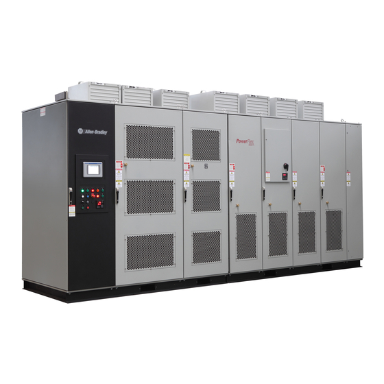
Allen-Bradley PowerFlex 6000 Installation Instructions Manual
Medium voltage variable frequency drive
Hide thumbs
Also See for PowerFlex 6000:
- Firmware, parameters, and troubleshooting manual (214 pages) ,
- User manual (146 pages) ,
- Installation manual (88 pages)
Table of Contents
Advertisement
Quick Links
Download this manual
See also:
User Manual
Advertisement
Table of Contents

Related Manuals for Allen-Bradley PowerFlex 6000


Summary of Contents for Allen-Bradley PowerFlex 6000
- Page 1 Installation Instructions PowerFlex 6000 Medium Voltage Variable Frequency Drive Installation Manual Publication 6000-IN006F-EN-P...
-
Page 2: Important User Information
Arc Flash. Arc Flash will cause severe injury or death. Wear proper Personal Protective Equipment (PPE). Follow ALL Regulatory requirements for safe work practices and for Personal Protective Equipment (PPE). Allen-Bradley, Rockwell Software, Rockwell Automation, PowerFlex, and TechConnect are trademarks of Rockwell Automation, Inc. Trademarks not belonging to Rockwell Automation are property of their respective companies. -
Page 3: Table Of Contents
Table of Contents Important User Information ........2 Preface Introduction. - Page 4 Table of Contents Introduction ..........35 MV Door Safety Interlock.
-
Page 5: Preface
This manual provides information specific for physically unloading and situating What Is Not in this Manual a PowerFlex 6000 drive. It does not include project-specific, or drive-specific topics such as: • Dimensional Drawings and Electrical Drawings generated for each customer’s order. -
Page 6: General Precautions
Commissioning Support After installation, Rockwell Automation is responsible for commissioning activities for the PowerFlex 6000 product line. Contact your local Rockwell Automation sales representative to arrange commissioning. Rockwell Automation support includes, but is not limited to: •... -
Page 7: Contractor Scope Of Work
Preface You can view or download publications at http:/www.rockwellautomation.com/literature/. To order paper copies of technical documentation, contact your local Allen-Bradley distributor or Rockwell Automation sales representative. Contractor Scope of Work Typical scope of work by the freight company, third-party contractor and/or customer (based on ex-works INCO terms) •... - Page 8 Preface Notes: Rockwell Automation Publication 6000-IN006F-EN-P - March 2018...
-
Page 9: Drive Mechanical Installation
The PowerFlex 6000 drive is shipped in two sections, the Isolation Transformer Cabinet and Power Module/LV Control Cabinet. These two cabinets must be connected after located in its final position. - Page 10 Chapter 1 Drive Mechanical Installation 1. Arrange the sections as directed in the Dimensional Drawings and move the sections together. 2. Align the cabinet side sheets together at the holes for the hardware (see step Figure 1 - Aligning Cabinets, Type A (6/6.6 kV shown) Optional Cabinets 1.
- Page 11 Drive Mechanical Installation Chapter 1 Figure 2 - Aligning Cabinets, Type B (6 kV shown) Power Module/LV Control Cabinet Isolation Transformer Cabinet Table 2 - Sidesheet Openings ❶ Front Wireway ❶ U Phase Motor Cable ❷ ❷ V Phase Motor Cable ❸...
- Page 12 Chapter 1 Drive Mechanical Installation 3. Secure the cabinets together using M6 or M8 hardware. See Torque Requirements on page 49 for proper torque requirements. Open the doors to access front edge joining holes (four or five places). Figure 3 - Secure the Cabinets, Type A Secure with M8 (or M10) hardware (10 places) Cabinet sidesheets...
-
Page 13: Affix Cabinets To Floor
Drive Mechanical Installation Chapter 1 4. Remove all back plates to access rear edge joining holes (five places). Each back plate will have two keyhole screw holes on either side. Remove all of the other screws first. Loosen the two screws in the keyhole screw holes last and lift the back plate to remove. - Page 14 Chapter 1 Drive Mechanical Installation Figure 6 - Typical Floor Drawing, Type B Power Module/LV Control Cabinet Isolation Transformer Cabinet Input cable Control signal Output cable Bottom View Secure the cabinet to the channel steel base using M12 bolt (recommended), lock washer, two flat washers and a nut.
- Page 15 Each weld location should be 100 mm (3.9 in.) for every 1000 mm (39.4 in.). See Mounting Requirements in the PowerFlex 6000 Medium Voltage Variable Frequency Drive Shipping and Handling Manual, publication 6000-IN008) for further information on the steel base and desired trench and mounting specifications.
-
Page 16: Install Main Cooling Fans
Main cooling fans are shipped in separate crates. The fans are shipped assembled in the fan housing, but must be installed after siting the drive. See Mounting Clearance Distance in the PowerFlex 6000 Medium Voltage IMPORTANT Variable Frequency Drive Shipping and Handling Manual, publication... -
Page 17: Install Power Modules (If Applicable)
Drive Mechanical Installation Chapter 1 Figure 11 - Main Cooling Fan Housing, Type B Main Cooling Fan housing Socket Aviation plug Rear View Install Power Modules (if Power Modules are available in a wide variety of amperage ratings relating to the required motor current. - Page 18 Chapter 1 Drive Mechanical Installation Figure 12 - Lift Cart Procedure 1. Check the lift tray before use to ensure the tray can be raised and lowered smoothly. 2. Rotate the Pressure Release Knob counterclockwise to ensure that the tray is in Hand Crank the lowest position.
-
Page 19: Install Power Modules
Drive Mechanical Installation Chapter 1 Install Power Modules The Power Module should be handled carefully. After removing the packaging, IMPORTANT inspect the Power Module to confirm there is no damage and moisture. 1. You can use the lift cart to move and position the Power Module to the appropriate location in the cabinet. -
Page 20: External Ducting
• External ducting including an external filtering system must not add more than 50 Pa (0.2 in. of water) pressure drop to the PowerFlex 6000 drive air flow system. Ensure a minimum top clearance of 1500 mm (39.4 in.) above the drive top plate. - Page 21 Drive Mechanical Installation Chapter 1 Figure 13 - Cabinet Airflow, Type A Figure 14 - Cabinet Airflow, Type B (1) Top ducting shown by contractor. Rockwell Automation Publication 6000-IN006F-EN-P - March 2018...
-
Page 22: Air Conditioning Sizing
Chapter 1 Drive Mechanical Installation Air Conditioning Sizing If the drive is located in an enclosed space, install air conditioners for each drive. A general formula to calculate air conditioner power required: × DriveRating kW 1 DriveEfficiency – Air Conditioning Size (tons) ------------------------------------------------------------------------------------------------------------ - = For a 1000 kW drive with 96.5% efficiency: EXAMPLE... -
Page 23: Drive Electrical Installation
Chapter Drive Electrical Installation Introduction The installation of all external power cables and control signal wiring is covered in this chapter. General electrical safety and installation guideline topics are also included. The basic activities include connecting the system ground cable, line and motor cables, control power, and all control signal wiring from the sources to the drive. -
Page 24: Electrical Drawings
• Terminal block designations for all connections to external customer control signal wiring and control power supply cables. The practice used within the PowerFlex 6000 electrical drawing is based on the IEC or NEMA standard depending on the requirements. The symbols used to identify components on the drawings are international. -
Page 25: Power Cable Insulation Requirements
Drive Electrical Installation Chapter 2 Attach an external ground cable to the main ground bus, in compliance with applicable national and local electrical codes. The primary grounding cable must have a diameter of at least 50 mm IMPORTANT meet all applicable national and local electrical codes. Run the system ground cable separately from power and signal wiring so that faults: •... -
Page 26: Power Cable Design Considerations
0.1 ohms. Spacing between wire groups is the recommended minimum for parallel runs of approximately 61 m (200 ft) or less. PowerFlex 6000 drives are able to operate motors if the cable length is less IMPORTANT than 400 m (1313 ft). -
Page 27: Control Signal Wiring Design Considerations
Use shielded cables for all the analog and digital control cables. Considerations Steel conduit or a cable tray can be used for all PowerFlex 6000 drive power or control wiring; however, use only steel conduit for all signal wiring. ATTENTION: Steel conduit is required for all control and signal circuits when the drive is installed in European Union countries. -
Page 28: Electrical Installation Summary
Chapter 2 Drive Electrical Installation Grounding provisions for control signal wiring is shown in Figure Figure 15 - Vertical Ground Bus in LV Cabinet Type A Type B Vertical Ground Bus Provisions for Grounding Control Signal Wiring Shields, and so on. Ground Bus Provisions for Grounding Control Signal Wiring Shields,... -
Page 29: Insulation Resistance (Ir) Test Of Power Cables
M8x25 bolt If an optional cabinet is supplied, the system ground cable connection is in the IMPORTANT optional cabinet. Refer to the PowerFlex 6000 Medium Voltage Variable Frequency Drive User Manual, publication 6000-UM002. Insulation Resistance (IR) Before connecting the incoming line and outgoing motor power cables, follow... - Page 30 Outgoing Motor Cable Connections If an optional cabinet is supplied, the incoming line and outgoing motor cable IMPORTANT connections are in the Bypass cabinet. Refer to the PowerFlex 6000 Medium Voltage Variable Frequency Drive User Manual, publication 6000-UM002. Figure Figure...
- Page 31 Drive Electrical Installation Chapter 2 Figure 19 - Isolation Transformer Cabinet, Type B (Junction cabinet not applied) Door position limit switches Voltage Sensing Board Incoming line power cable connections Outgoing motor power cable connections Power cable connections to Power Modules Isolation Transformer Cable clamp Figure 20 - Isolation Transformer Cabinet, Type C (Junction cabinet applied for cable connection)
-
Page 32: Connect Control Power Wiring
Chapter 2 Drive Electrical Installation Connect Control Power Introduction Wiring Externally supplied control power is required to operate the drive. The standard voltage supported is 220V AC/50 Hz. The other typical phase voltages of 230V AC, 110V AC, and 120V AC are also supported (50/60 Hz), but need to be specified at the time of order. - Page 33 Drive Electrical Installation Chapter 2 Figure 22 - Control Power Wiring Opening, Type B Cable entrance in top or bottom front of LV Control Cabinet The control power wiring terminates to the DTB1 terminal block strip on the left side of the LV Control cabinet (Figure 23).
-
Page 34: Connect External Control Signal Wiring
Chapter 2 Drive Electrical Installation Connect External Control Introduction Signal Wiring This section summarizes the control signal wiring from the remote DCS/PLC or discrete control to the drive. General connections are detailed in Power Cabling and Control Signal Wiring Details on page 53. -
Page 35: Connect Electrical Safety Interlock Circuit To Input Circuit Breaker
• indicate to the drive when the input circuit breaker is closed. MV Door Safety Interlock If the MV cabinet door is opened, the Allen-Bradley Guardmaster Limit Switch (440P-CRPS11D4B) on the cabinet door will actuate. The drive will send a trip signal to the input circuit breaker to disconnect the medium voltage power supply to the drive. - Page 36 Chapter 2 Drive Electrical Installation When the doors of the Power Module/LV Control Cabinet or Isolation Transformer Cabinet are not closed, when the drive is being maintained or when the control power switch is not closed, the drive will not send a signal allowing the input circuit breaker to close;...
-
Page 37: Introduction
Chapter Drive Electrical Interconnection Introduction The drive is shipped in two sections, the Isolation Transformer cabinet and the Power Module/LV Control cabinet. An optional cabinet may also be supplied. Drive Mechanical Installation on page 9 describes mechanically joining these cabinets together. This chapter describes the activities required to electrically connect these drive cabinets’... -
Page 38: Connect Isolation Transformer Secondary Power Cables
Chapter 3 Drive Electrical Interconnection Refer to the Electrical Drawing for actual wire number designations. Figure 25 - Power Cabling Overview (3.3 kV shown) Motor Isolation Transformer Voltage Sensing Board PC A1 PC A2 PC A3 PC B1 Input power 3-phase AC PC B2 any voltage... - Page 39 Drive Electrical Interconnection Chapter 3 Figure 26 - Isolation Transformer Primary and Secondary Winding Orientation PRIMARY WINDING INPUT A (L1) B (L2) C (L3) The secondary windings are brought out to corresponding vertical isolated stand- offs on the body of the transformer (orientated U, V, and W from left to right as viewed from the front).
-
Page 40: Cable Routing And Connection
Chapter 3 Drive Electrical Interconnection Each three-phase secondary winding set of the isolation transformer has three individual single phase power cables connecting its output to the three-phase power input of its corresponding power module. Drives are shipped split with an Isolation Transformer cabinet and a Power Module cabinet, and connection at the site is needed. -
Page 41: Connect Motor And Voltage Sensing Board Cables
Drive Electrical Interconnection Chapter 3 Connect Motor and Voltage Introduction Sensing Board Cables The Voltage Sensing Board cables and the motor cables both connect to the same output point of each motor phase array (Figure 25). The voltage sensing cables needs to be connected on site. For drive ratings with power modules ≥250 A, the connection points are always on the right side of the power module cabinet. -
Page 42: Connect Lv Control And Fan Wiring Bundles
Chapter 3 Drive Electrical Interconnection Connect LV Control and Fan Introduction Wiring Bundles There are control wiring bundles that must be reconnected after the drive cabinets are connected together. These control wiring bundles are connected for the factory test and then disconnected and bundled at the shipping splits before shipment. -
Page 43: Complete The Installation
Drive Electrical Interconnection Chapter 3 1. Inspect the interior of all cabinets carefully for hardware or tools that may Complete the Installation have been misplaced. 2. Check and verify that no hardware or foreign material has fallen in the secondary windings in the Isolation Transformer cabinet. 3. - Page 44 Chapter 3 Drive Electrical Interconnection Notes: Rockwell Automation Publication 6000-IN006F-EN-P - March 2018...
-
Page 45: Pre-Commissioning Responsibilities
Appendix Pre-Commissioning Pre-Commissioning Rockwell Automation manages the start-up service for each installed drive at the customer’s site, but there are a number of tasks the customer or its representatives Responsibilities must complete before scheduling Rockwell Automation personnel for drive commissioning. Review this information prior to commissioning the drive as a reference for drive line-up commissioning. -
Page 46: Pre-Commissioning Checklist
Appendix A Pre-Commissioning Pre-Commissioning Checklist Once all points of the checklist are complete, initial each check box and provide the date. Photocopy the checklist and fax the copy to the Rockwell Automation Start-up Manager, along with the planned start-up date. Upon receiving this checklist, the Project Manager will contact the site to finalize arrangements for a start-up engineer to travel to the site at your convenience. - Page 47 Pre-Commissioning Appendix A Table 10 - Control Wiring: Initials Date Check All low voltage wiring entering the drive is labeled, appropriate wiring diagrams are available, and all customer interconnections are complete. All AC and DC circuits are run in separate conduits. All wire sizes used are selected by observing all applicable safety and national and local electrical codes.
- Page 48 Appendix A Pre-Commissioning Table 13 - Drive Line-up Status Initials Date Check The medium voltage and low voltage power is available for startup activities. The motor is uncoupled from the driven load. The load is available for full load testing. Rockwell Automation Publication 6000-IN006F-EN-P - March 2018...
-
Page 49: Torque Requirements
Appendix Torque Requirements Torque Requirements Proper tightening torque must be used for installation and wiring. Table 14 - Torque Requirements Torque Thread Size Class 8.8 N•m lb•ft 10.5 26.0 19.2 51.0 37.6 89.0 65.7 141.0 104.1 215.0 158.7 420.0 310.0 Rockwell Automation Publication 6000-IN006F-EN-P - March 2018... - Page 50 Appendix B Torque Requirements Notes: Rockwell Automation Publication 6000-IN006F-EN-P - March 2018...
-
Page 51: General Wire Categories
Appendix General Wire Categories General Wire Categories Conductors Conductors Machine With Signal Examples Recommended Conductors Power Control To PLC Category Group Cable Group Supplies mm (in.) mm (in.) Power Supplies AC power supply 220V, 1Ø Per IEC / NEC, Tray All signal wiring must be run 228.6 (9.00) 152.4 (6.00) - Page 52 Appendix C General Wire Categories Notes: Rockwell Automation Publication 6000-IN006F-EN-P - March 2018...
-
Page 53: Schematic Diagrams
Appendix Power Cabling and Control Signal Wiring Details Schematic Diagrams Figure 30 - Schematic Diagram of the Drive System without a Bypass Cabinet (1) Wiring locations are for design reference only; actual wiring must comply with the drawings provided with the drive. Rockwell Automation Publication 6000-IN006F-EN-P - March 2018... - Page 54 Appendix D Power Cabling and Control Signal Wiring Details Figure 31 - Terminal Strip Wiring Diagram for Drive System without a Bypass Cabinet Rockwell Automation Publication 6000-IN006F-EN-P - March 2018...
-
Page 55: Standard Input/Output Connection Points
Power Cabling and Control Signal Wiring Details Appendix D Standard Input/Output Connection Points Table 15 - Standard I/O Connections Points Serial Number Name of I/O Connection Note Input circuit breaker closing node is allowed Serially connected into the input circuit breaker's closing circuit (917, 918) (the VFD provides passive normally open points, valid when closed) Input circuit breaker closing node is allowed... - Page 56 Appendix D Power Cabling and Control Signal Wiring Details Table 16 - I/O Connections related to Remote Distributed Control System (Continued) Serial Number Name of I/O Connection Note Alternate reset command (412, 401) User-provided normally open passive dry contact Emergency stop button command User-provided normally closed passive dry contact (1101, 1102) (voltage class higher than 220V AC, 5 A, switch quantity)
- Page 57 Appendix Line and Load Cable Sizes The data in the following tables are informative only; do not base final design criteria solely on this data. Follow national and local installation codes, industry best practices, and cable manufacturer recommendations. As cabling methods can very widely, maximum cables sizes do not account for the size of the conduit hub.
- Page 58 Appendix E Line and Load Cable Sizes Table 18 - Line and Load Cable Sizes for UL (In ≤200 A) Description Drive Enclosure Max. Size & No. Incoming (1) (2) (3) (Motor V/Freq.) Opening mm (in.) Cables: UL Maximum Line 2300/2400 V, 50/60 Hz 1150 x 200 (45.3 x 7.9) 300 mm²...
- Page 59 Line and Load Cable Sizes Appendix E Table 19 - Line and Load Cable Sizes for IEC and UL (210 ≤ In ≤ 680 A) Description Drive Enclosure Max. Size & No. Incoming (1) (2) (3) (Motor V/Freq.) Opening mm (in.) Cables: UL Maximum Line 2400 V, 50/60 Hz...
- Page 60 Appendix E Line and Load Cable Sizes Notes: Rockwell Automation Publication 6000-IN006F-EN-P - March 2018...
- Page 61 Index Cooling Fans Dimensions 16 Additional Resources 6 Hardware 16 Air Conditioning Installation 16 Calculation 22 Model 16 Sizing 22 Orientation 16 Anchor bolts 13 Weight 16 Wiring Bundles 42 ASHRAE Standard 52.2 MERV 11 20 Aviation Plug 16 Design Considerations 27 Documentation box Back Plates Electrical Drawings 24...
- Page 62 Index Electrial Safety Interlock 35 Junction Cabinet Electrical Drawings 24 Location 31 Contents 24 Electrical Safety Interlock Location 35 Wire Routing 36 Lift Cart 17 EU EN779 Class F6 20 Lifting capacity 17 External Control Signal Wiring 34 Operation 17 Lifting Angles Analog I/O 34 Digital I/O 34...
- Page 63 Voltage Sensing Board connection 41 Standard Input/Output Connection Points 55 Weight 18 System Ground Cable Power Terminals 30 Installation 28 PowerFlex 6000 Location 28 Electrical Installation 23 Torque Requirements 49 External Ducting Specifications 20 Isolation Transformer Cabinet Layout 30 Line Cable Sizes 57...
- Page 64 Index Notes: Rockwell Automation Publication 6000-IN006F-EN-P - March 2018...
- Page 66 Medium Voltage Products, 135 Dundas Street, Cambridge, ON, N1R 5X1 Canada, Tel: (1) 519.740.4100, Fax: (1) 519.623.8930 Online: www.ab.com/mvb Allen-Bradley, Rockwell Software, Rockwell Automation, and TechConnect are trademarks of Rockwell Automation, Inc. Trademarks not belonging to Rockwell Automation are property of their respective companies.
Need help?
Do you have a question about the PowerFlex 6000 and is the answer not in the manual?
Questions and answers