Sign In
Upload
Manuals
Brands
Allen-Bradley Manuals
DC Drives
The PowerFlex 755 On-Machine
Allen-Bradley The PowerFlex 755 On-Machine Manuals
Manuals and User Guides for Allen-Bradley The PowerFlex 755 On-Machine. We have
1
Allen-Bradley The PowerFlex 755 On-Machine manual available for free PDF download: User Manual
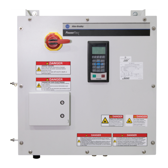
Allen-Bradley The PowerFlex 755 On-Machine User Manual (218 pages)
Brand:
Allen-Bradley
| Category:
DC Drives
| Size: 35.96 MB
Table of Contents
Table of Contents
3
Summary of Changes
7
Conventions Used in this Manual
7
Additional Resources
8
Getting Started
11
System Overview
11
System Identification Diagram
11
Data Nameplate and UL Listing
12
System Configuration Example
13
Armorconnect Power Media
15
Catalog Number Explanation
16
Prepare for Installation
17
Precautions
17
Electrical Safety Considerations
19
Environment and Enclosure
19
Environment
20
Wiring and Workmanship Guidelines
20
Electromagnetic Compatibility (EMC)
21
General Notes
21
Wiring
22
Power Requirements
22
Circuit Protection
23
Short-Circuit Current Rating (SCCR)
24
Circuit Breakers
24
Branch Circuit Protection Requirements for Three-Phase Power Media
25
Minimum Mounting Clearances
26
Dimensions
27
Receive, Unpack, and Inspect the Drive
28
Receiving
28
Unpack and Inspect
30
Lift and Transport the Drive
31
Two-Person Lifting
33
Apply Labels to the Drive
34
Install the Drive
35
Mount the Drive
35
Ground the Drive
36
Grounding Safety Grounds
36
Grounding PE or Ground
37
Shield and Ground Motors and Motor Cables
37
Select Cables
38
Control Power
44
24V DC Control Power Receptacle
44
Make Connections
44
Receptacle Configurations on the Gland Plate
44
Receptacle Connections
47
Configure and Start up the Drive
49
Prepare for Initial Drive Startup
49
Set the Network IP Address of the 1783-ETAP
50
Ethernet/Ip Adapter
51
Energize the HIM
51
Access Parameters
53
Set the Adapter IP Address
53
Startup Introduction
56
Controller Organizer
56
Add-On Profiles
57
Configuration Requirements
57
Choose Startup Mode
58
Drive Startup - I/O Mode
59
Add the Powerflex 755 Drive to Your Project
60
Update the Module Properties
63
Verify Drive Data
66
Choose Integrated or Hard-Wired Safety
67
Safety Configuration for SSM and S4
69
Configure the Drive Parameters
72
Setup the Datalinks
85
Create Safety Logic to Control the Safety Module
86
Configure an RS Trend
88
Save and Download Project
92
Go Online with the Logix Controller
93
Put the Logix Controller into Run Mode
95
Turn Safety on (SSM and S4 Only)
96
Energize the Incoming Power and Brake Circuit Breakers
96
Perform Motor Auto Tune Tests
97
Application Tuning
108
Connect the Motor to the Machine
109
Synchronize the Drive
110
Application Notes
111
Drive Startup - Integrated Motion Mode (CIP Motion)
112
Add Drive to the I/O Project
112
Option Modules
114
Create an Associated Axis
116
And Control Mode
127
Specify the Motor Data Source
130
Drive Safety Circuits
135
Save and Download the Project
135
Verify the Controller Is Online
137
Commission and Tune the Motor and Drive
138
Autotune
142
Manual Tune
143
Save Commissioned Axis to the Logix Project
144
Drive Maintenance
145
Repair and Replacement Procedures
145
Remove Power
146
Remove the Front Cover
148
Replace the Surge Suppressor AC Source Brake (1SUP270)
150
Replace the DC Brake Surge Suppressor (1BD0270)
151
Replace the Brake Contactor (5BC130)
152
Replace the Main Circuit Breaker (1CB030)
153
Replace Powerflex Frame 2 Drive (1EA030)
156
Replace the Powerflex Frame 2 Heatsink Fan
160
Replace Option Modules
160
(5CB070 and 1CB250 or 5CB130)
161
Replace the Drive HIM (1HIM320)
162
Replace the EMC Kit (1CH030)
163
Replace the ETAP Module (6ET210)
163
Replace Receptacles on the Gland Plate
164
Receptacle Replacement - Type 1
166
Receptacle Replacement - Type 2
166
Receptacle Replacement - Type 3
167
Receptacle Replacement - Type 4
167
Receptacle Replacement - Type 5
168
Receptacle Replacement - Type 6
168
Attach the Front Cover
169
Apply Power
170
Troubleshooting
173
Electrical Safety Considerations
173
Fault Types, Descriptions, and Actions
174
Circuit Breaker Troubleshooting
176
Open Auxiliary Circuit Breaker Door
176
Reset Drive Via the Circuit Breaker Switch
177
Encoder Feedback Considerations
179
Potential Encoder Feedback Issues
179
Encoder System Components
180
Mechanical Checks
181
Positioning Troubleshooting Flowcharts
182
Troubleshooting Going Online
185
View Adapter Status by Using Parameters
185
Access the Adapter Web Pages
185
Set a Fault Action
188
Restore Adapter Parameters to Default Configurations
190
Updating the Drive Firmware
191
Recommended Preventive Maintenance
195
Schedule Codes Explanations
196
Maintenance of Industrial Control Equipment
197
Induction Motor 400/480 AC Source Brake
203
Induction Motor 24V DC Mechanical Brake
204
Servo Motor 24V DC Mechanical Brake
205
Gland Plate Receptacles
206
Prepare for Initial Drive Startup
207
Index
209
Advertisement
Advertisement
Related Products
Allen-Bradley PowerFlex 70
Allen-Bradley PowerFlex 70 Enhanced Control
Allen-Bradley PowerFlex 700 Vector Control
Allen-Bradley PowerFlex 6000
Allen-Bradley PowerFlex 7000 Series
Allen-Bradley PowerFlex AFE
ALLEN BRADLEY PowerFlex 4M
Allen-Bradley PowerFlex 22-COMM-E
Allen-Bradley PowerFlex SK-RM-CARTCLIP
Allen-Bradley 1395
Allen-Bradley Categories
Control Unit
Controller
I/O Systems
Power Supply
Switch
More Allen-Bradley Manuals
Login
Sign In
OR
Sign in with Facebook
Sign in with Google
Upload manual
Upload from disk
Upload from URL