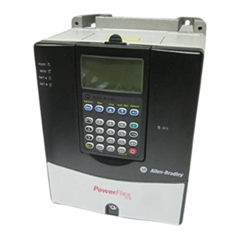
Allen-Bradley PowerFlex Installation Instructions Manual
Hide thumbs
Also See for PowerFlex:
- Installation manual ,
- User manual (118 pages) ,
- Installation instructions manual (12 pages)
Advertisement
PowerFlex® DC Drive
Frame D Pulse Transformer Circuit Board
Installation Instructions
What This Kit Includes
Tools That You Need
What You Need to Do
ATTENTION: Only qualified personnel familiar with DC drives
and associated machinery should plan or implement the installation,
start-up and subsequent maintenance of the system. Failure to comply
may result in personal injury and/or equipment damage.
ATTENTION: To avoid an electric shock hazard, ensure that all
power to the drive has been removed before performing the following.
ATTENTION: This drive contains ESD (Electrostatic Discharge)
sensitive parts and assemblies. Static control precautions are required
when installing, testing, servicing or repairing this assembly.
Component damage may result if ESD control procedures are not
followed. If you are not familiar with static control procedures,
reference A-B publication 8000-4.5.2, "Guarding Against
Electrostatic Damage" or any other applicable ESD protection
handbook.
• Pulse transformer circuit board
• Six screws and washers
• 6 gate lead cables with connectors (for non-regenerative drives only)
• 12 gate lead cables with connectors (for regenerative drives only)
• Static strap
• Phillips
®
screwdriver
• Hexalobular screwdriver
• Nut driver or wrench
®
Phillips
is a registered trademark of Phillips Screw Company.
To install the switching power supply board:
Step 1: Remove power from the drive
Step 2: Remove the protective covers
Step 3: Remove the switching power supply board
Step 4: Remove the existing pulse transformer board
Step 5: Install the new pulse transformer board
Step 6: Install the switching power supply board
Step 7: Replace the protective covers and document the change
Publication 20P-IN050A-EN-P
Advertisement
Table of Contents

Summary of Contents for Allen-Bradley PowerFlex
- Page 1 PowerFlex® DC Drive Frame D Pulse Transformer Circuit Board Installation Instructions ATTENTION: Only qualified personnel familiar with DC drives and associated machinery should plan or implement the installation, start-up and subsequent maintenance of the system. Failure to comply may result in personal injury and/or equipment damage.
-
Page 2: Step 1: Remove Power From The Drive
Step 1: Remove Power from the Drive ATTENTION: Remove power before making or breaking cable connections. When you remove or insert a cable connector with power applied, an electrical arc may occur. An electrical arc can cause personal injury or property damage by: •... - Page 3 Figure 1 Cover Removal Tightening torque: 1.5 N•m (13 lb•in) Top control pan cover Bottom control pan cover Disconnect DPI cable 4. Disconnect the HIM communication cable from the connector on the upper right corner of the Control board and remove the bottom cover. Pull tabs out to disconnect cable.
-
Page 4: Switching Power Supply Board
Step 3: Remove the 1. Loosen the eight hexalobular screws that secure the protective plastic cover to the control pan and remove the cover. Switching Power Supply Board Loosen screw PFC -XX Switching Power Supply board Loosen Loosen screws screws Pulse Transformer board Loosen screw... - Page 5 Figure 2 Switching Power Supply Circuit Board Layout Tightening torque: 1.0…1.2 N•m (9…10.5 lb•in) XSW1 Step 4: Remove the 1. Disconnect the (red and white) gate leads from connectors XP1 and XP2 at the top-left corner of the board. Existing Pulse Transformer Board 2.
- Page 6 Figure 3 Pulse Transformer Circuit Board Layout Components shown within dashed lines are only on the pulse transformer board for regenerative drives. XSW1 Tightening torque: 1.0…1.2 N•m (9…10.5 lb•in) XCD_IO XUVW KG01 KG04 KG02 KG05 KG03 KG06 XSPF 78 79 35 36 75 76 81 82 U2 V2 Publication 20P-IN050A-EN-P...
- Page 7 Step 5: Install the New Install the new pulse transformer board in reverse order of removal as detailed in Step 4: Remove the Existing Pulse Transformer Board on page Pulse Transformer Board • Inspect the existing gate lead cables for burn marks, cracks or loose connectors.
-
Page 8: Related Documentation
For . . . Read this document Number In depth information regarding the User Manual - PowerFlex Digital DC Drives 20P-UM001… operation of PowerFlex Digital DC drives www.rockwellautomation.com Power, Control and Information Solutions Americas: Rockwell Automation, 1201 South Second Street, Milwaukee, WI 53204-2496 USA, Tel: (1) 414.382.2000, Fax: (1) 414.382.4444...


Need help?
Do you have a question about the PowerFlex and is the answer not in the manual?
Questions and answers