Table of Contents
Advertisement
Quick Links
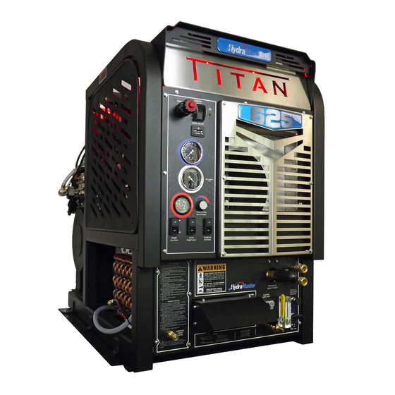
Titan 625
Owner's Manual
HydraMaster
11015 47
Avenue West
th
Mukilteo, Washington 98275
MAN-47854 REV A. October 2021
(P/N: 000-182-306D)
No part of this manual may be reproduced or used in any form or by any means (i.e. graphic, electronic, photocopying or electronic
retrieval systems) without the express written permission of HydraMaster. Specifications and information in this document are
subject to change without prior notice. All rights reserved. © 2021 HydraMaster
Advertisement
Table of Contents

Subscribe to Our Youtube Channel
Related Manuals for HydraMaster Titan 625


Summary of Contents for HydraMaster Titan 625
- Page 1 No part of this manual may be reproduced or used in any form or by any means (i.e. graphic, electronic, photocopying or electronic retrieval systems) without the express written permission of HydraMaster. Specifications and information in this document are subject to change without prior notice. All rights reserved. © 2021 HydraMaster...
-
Page 3: Table Of Contents
High Altitude Operation ..................1-15 Local Water Precautions .................. 1-15 INSTALLATION INFORMATION ..............SECTION 2 Operating theTitan 625 in Hot Weather.............. 2-2 Setting Up the Titan 625..................2-5 Orientation of Fuel Pump ................... 2-6 CLEANING AND CHEMICALS ..............SECTION 3 Precautions ......................3-1 Preparing the Carpet for Extraction.............. - Page 4 High Pressure System ..................8-8 Vacuum System ....................8-10 ASSEMBLIES AND PARTS LISTS ............SECTION 9 Titan 625 With 100 Gallon URT Assembly Parts List ..........9-4 Titan 625 With 70 Gallon URT Assembly Parts List ..........9-6 Console Assembly Parts List .................9-12 Blower Assembly Parts List ..................9-14...
- Page 5 Chemical System ....................11-1 Control Panel ....................11-1 Vacuum and Solution Hoses ................11-2 Cleaning Wand and Tool ...................11-2 Water Heating System ..................11-2 Hard Water Deposits ..................11-2 Warranty Procedure ..................11-2 ACCESSORIES AND CHEMICAL SOLUTIONS ........SECTION 12 iii - Titan 625 Owner’s Manual...
- Page 6 Figure 1-1. Hard Water Map of Mainland United States ..........1-16 Figure 2-1. Location of Roof Vents in Vehicle ..............2-1 Figure 2-2. Recommended Location of Titan 625 in Van ..........2-3 Figure 2-3. Install Fuel Pump, Outlet Side Up ..............2-6 Figure 2-4. Fuel Pump Must Be in Vertical Position .............2-6 Figure 4-1.
- Page 7 Figure 7-3. Wiring Diagram - View 2 of 2 ..............7-4 Figure 9-1. Adhesive/ Material Reference ..............9-2 Figure 9-2. Titan 625 with 100 gallon URT ..............9-3 Figure 9-3. Titan 625 with 70 gallon URT ..............9-5 Figure 9-4. Console Assembly - View 1 of 5 ..............9-7 Figure 9-5.
- Page 8 Figure 9-40. Sacrificial Anode Assembly ..............9-58 Figure 9-41. AWDS Universal Kit Assembly ...............9-59 Figure 9-42. High Pressure Washing Kit - Pump Assembly ........9-61 Figure 9-43. High Pressure Washing Kit - Lower Left Dash Assembly ......9-63 Titan 625 Owner’s Manual - vi...
- Page 9 1- General Information The simple but powerful Titan™ 625 is a carefully engineered truckmount carpet cleaning machine designed and manufactured by HydraMaster. A Kohler 38 HP EFI Engine powers the 625’s Gardner Denver TF408 vacuum blower and the high pressure water pump, which is rated at 4 gpm.
-
Page 10: General Information
It is imperative that no section of this manual be overlooked when preparing for operation of the Titan 625. Please read the manual to familiarize yourself with the operation of your Titan 625, paying special attention to all Warnings and Cautions. -
Page 11: System Concept
SYSTEM CONCEPT This is how the Titan 625 works: Incoming water enters the water box and is pressurized by the high pressure water pump. The water is heated by the engine exhaust in the blower exhaust heat exchanger. Cleaning solution is then injected into the pressurized water stream and the heated solution is delivered to the cleaning tool. -
Page 12: Contact Information
To find a local distributor, please visit our website at https://hydramaster.com/dealer-locator/ If your question cannot be resolved by your distributor or by the information within this manual, you may contact HydraMaster direct using the following phone numbers. HOURS TELEPHONE NUMBERS... -
Page 13: Warnings, Cautions And Notices
WARNINGS, CAUTIONS AND NOTICES HydraMaster uses this WARNING symbol throughout the manual to warn of possible injury or death. This CAUTION symbol is used to warn of possible equipment damage. This NOTICE symbol indicates that federal or state regulatory laws may apply, and also emphasizes supplemental information. - Page 14 Transporting a vented fuel container that presently contains, or has ever contained in the past, a flammable liquid is strictly forbidden by HydraMaster and by federal and state regulations. Doing so will increase the risk of fire and explosion. Serious injury or death may result.
- Page 15 Never smoke in or around the truckmount. Doing so will increase the risk of fire and explosion. Serious injury or death may result. During the operation of the truckmount the exhaust system will become extremely hot. Keep all flammable materials away from the truckmount exhaust system. Failure to do so will increase the risk of fire and explosion.
- Page 16 Never allow water to freeze inside the truckmount. Serious component damage will occur. Perform all freeze guarding procedures outlined in this digital Owner’s Manual. Many vehicles have critical components mounted directly below the floor that can easily be damaged. Before drilling holes in the floor of the vehicle inspect the underside of the vehicle for critical components.
-
Page 17: Responsibilities
RESPONSIBILITIES Purchaser’s Responsibilities • Prior to purchasing a van, ensure that the payload is suitable for all of the equipment that will be installed and transported. This includes and is not limited to: the truckmount, recovery tanks, fresh water tanks and any other on-board water, hose reels, hoses, cleaning tools, chemicals and drying equipment. - Page 18 • Ensure proper connection of the fuel lines. • Ensure proper connection and installation of the battery. Verify that the battery is in accordance with HydraMaster’s recommendation. • Check the pump, vacuum blower and engine oil levels prior to starting the truckmount.
- Page 19 Training The distributor should provide a thorough review of the operation manual with the purchaser along with instruction and familiarization in: How all the truckmount’s systems function. All safety precautions and their importance. How to correctly start and shut down the truckmount. How to correctly clean with the truckmount.
-
Page 20: Machine Specifications
MACHINE SPECIFICATIONS Frame Dimensions 26.0" W x 45" D x 39" H Weight 850 lbs Engine - 38HP Kohler EFI Oil Type 5W-30 Synthetic* Capacity 2.7 quarts when changing oil and filter Engine rpm High - 2700 rpm Idle - 1,500 rpm Fuel Consumption 1.6 gph Ignition... - Page 21 Owner’s Manual (on USB) Owner’s Guide (printed) The Titan 625 comes standard with an exhaust deflector to which a hose cannot connect. HydraMaster strongly recommends you purchase the Exhaust Thru Floor Kit which directs the hot air outside of the van, away from the machine. This kit is highly recommended for vans with barn doors.
-
Page 22: Spare Parts
SPARE PARTS The following table is a list of available Titan 625 spares that distributors may purchase to have on hand for repairs and maintenance. Part No Description 000-010-128 Belt, 9330HD Pump Drive 000-010-131 Belt, 3vx450 Eng. Drive 000-025-033 Cable, Throttle... -
Page 23: High Altitude Operation
HIGH ALTITUDE OPERATION Elevation plays a key role in how truckmounts operate, however, with Titan 625’s Kohler engine, it is not required to change or adjust the fuel system due to changes in altitude. The Kohler engine electronic control system constantly monitors the barometric pressure and fuel mixture in the exhaust and will compensate for any altitude. -
Page 24: Figure 1-1. Hard Water Map Of Mainland United States
Cleaning efficiency and equipment life is increased, chemical use decreased, and the appearance of cleaned carpets enhanced when water softeners are incorporated in hard water areas. HydraMaster strongly urges the use of water softener units with the Titan 625 in areas exceeding 3.0 grains per gallon. - Page 25 Another solution to the disposal problem is to equip your Titan 625 with an Automatic Wastewater Disposal System (AWDS). These systems are designed to remove waste water from the extractor’s recovery system and actively pump the water through hoses to a suitable disposal drain.
-
Page 26: Installation Information
Although there are many different heavy duty vehicles used for carpet cleaning equipment, the preferable vehicle for a Titan 625 installation is a cargo van with a heavy-duty suspension package and a 3/4 HD ton capacity. If a fresh water tank is added, a one ton or larger capacity van is required. -
Page 27: Operating Thetitan 625 In Hot Weather
OPERATING THE TITAN 625 IN HOT WEATHER HydraMaster recommends the following steps when operating the Titan 625 during periods of hot weather (95º F or higher). This will help ensure that your Titan 625 continues to run at 100% capacity during even the hottest days. -
Page 28: Figure 2-2. Recommended Location Of Titan 625 In Van
Figure 2-2. Recommended Location of Titan 625 in Van Secure Installation No matter how the unit is installed, check to see if the Titan 625 is properly secured to the floor of the van with the hardware provided. This safety measure will ensure that the machine will not slide inside the van. - Page 29 Transporting any vented fuel container that presently holds or has ever held a flammable liquid in a vehicle containing the Titan 625 is strictly forbidden by HydraMaster Corporation and by federal and state regulation. The engine exhaust from this product contains chemicals known to the State of California to cause cancer, birth defects or other reproductive harm.
-
Page 30: Setting Up The Titan 625
Setting the vacuum level higher than the recommended value can result in an increased risk of serious component damage. The Titan 625 is shipped from the factory with antifreeze added to the solution system. Recover this antifreeze and dispose of the recovered antifreeze as stated in the local laws and regulations. -
Page 31: Orientation Of Fuel Pump
ORIENTATION OF FUEL PUMP For proper fuel pump operation and fuel flow, the vehicle’s fuel pump must be installed in a lower position with respect to the fuel tank and in as vertical a position as possible outlet side up - Black = Negative see Figure 2-3 and Figure 2-4). -
Page 32: Precautions
3 - Cleaning Information The Titan 625 has been engineered using the latest and most sophisticated technology available to produce the finest carpet cleaning results possible. Despite this, it remains only a tool of the carpet cleaning trade and can produce only as a good a job as the person operating it. -
Page 33: Preparing The Carpet For Extraction
Relying on the rinse detergent to do the majority of the cleaning will result in overly long dry times and excess detergent residue left in the carpet. HydraMaster recommends the use of our pre-sprays: Fastbreak™ for residential carpet and Blitz™ for commercial carpet needs. -
Page 34: Overwetting
OVERWETTING Overwetting is an annoyance to all concerned. Extended drying times will leave the customer with a negative impression of both the cleaning company and the process used. Several factors that will cause over-wetting include: Too few vacuum strokes. Clogged vacuum blower filter or vacuum tank lid not sealing properly. Vacuum tank drain valve left partially open. -
Page 35: Cleaning Tool Tips
CLEANING TOOL TIPS Wands With a wand, keep cleaning strokes short, front to back, and run a “dry pass”. After pulling the wand for a strip of 3 or 4 ft long with the solution trigger activated, go back up to the top of the stroke, and make a “dry “ pass [i.e. no solution flowing]. This gives the wand a second chance to pick up the solution on the carpet. - Page 36 3-5: Cleaning Information...
- Page 37 Only 8.8 lbs 2" Titanium Tube 16" Head 6 Stainless Steel Jets Item #000-163-054 16” ◂ 2” Titanium Truckmount Wand Only 6.8 lbs 1.5" Tube, 10" Head, Single Jet 10” Item #000-163-759 ◂ Evolution Stair Wand Cleaning Information: 3-6...
- Page 38 Only 6.8 lbs Item #000-163-058 2" Evolution Flood Wand 16” 3-7: Cleaning Information...
- Page 39 RX20 NEXT GEN Tool for Carpet, Hard Surface and Bonnet Cleaning Before turning on the RX20 NEXT GEN, adjust the handle; it should rest right below or even with the bottom of your pants’ front pockets, with the tool resting flat on the floor. Take your time in adjusting the tool’s height;...
- Page 40 Upholstery Tool - DriMaster 3 Use the upholstery tool on small rugs and furniture. When you clean rugs, be sure that the temperature and chemicals are safe for that particular type of rug. As with the larger tools, do not leave the surface of the upholstery too wet. Adjust the volume of water on the tool without it touching any surface: the water should just barely come out of the tool before the vacuum pulls it back in.
-
Page 41: Operating Instructions
4 - Operating Instructions This section describes how to operate the Titan 625, starting with a description of the dash assembly (see Figure 4-1). Power Switch with Guard Throttle (START, RUN and OFF) Cable MIL LED Pressure Gauge Vacuum Vacuum... -
Page 42: Figure 4-2. Titan 625 Lower Dash Assembly
• Water pressure • Chemical metering • Water box drain The lower dash assembly also houses the blower lube port and the two high pressure cleaning solution port where the wand/tools connect to the Titan 625. Chemical Pressure Control System Adjustment Regulator Figure 4-2. -
Page 43: Setting The Temperature
Photographs and illustrations included in this document can represent optional equipment as well as standard equipment. SETTING THE TEMPERATURE Depending upon the type of cleaning jobs you need to do, the temperature knob can be adjusted clockwise to increase or counter clockwise to decrease the solution temperature. Figure 4-3. -
Page 44: Start Up Procedure
After the engine starts, allow the truckmount to run in “IDLE” for 2 - 3 minutes to warm up. Never clean when the Titan 625 is in the “IDLE” mode. Failure to follow this caution may result in serious component or engine damage. -
Page 45: Setting The Pressure (For Optional High Pressure Washing Kit)
SETTING THE PRESSURE (FOR OPTIONAL HIGH PRESSURE WASHING KIT) Lower the pressure below 1,200 psi prior to moving the “WATER PRESSURE SELECTOR” valve to “CARPET CLEANING” mode. Failure to do so may result in serious component or engine damage. Set the cleaning pressure to the desired level as follows. Carpet Cleaning: 300 to 400 psi: Position the “WATER PRESSURE SELECTOR”... -
Page 46: Shut Down Procedure
Do NOT apply a vacuum load while using the Titan 625 in “PRESSURE WASHING” mode. Doing so may cause the machine to overheat. Turn the “CHEMICAL SYSTEM” switch to the “PRIME” position to purge any air from the system (see Figure 4-5). - Page 47 Cap off the inlet(s) to the vacuum tank. Spray a HydraMaster-recommended spray lubricant into the “BLOWER LUBE PORT” for about 5 to 10 seconds while the unit is running (see Figure 4-6). Allow machine to run additional 2 to 5 minutes under load to flush off lubricant.
-
Page 48: Machine Maintenance
A maintenance log, provided in the Owner’s Guide, must be correctly and completely filled out. HydraMaster may request to inspect the logs before a warranty claim is honored. It is recommended that the log be affixed to the vehicle door near the truckmount for convenience and to serve as a maintenance reminder. -
Page 49: Operational Maintenance
• Inspect the truckmount for water and oil leaks, loose electrical connections, etc. and repair as needed. • Lubricate the blower lube port with a HydraMaster-recommended lubricant. Weekly Maintenance • Inspect the recovery tank filters for tears, holes, etc. Repair or replace as needed. - Page 50 Quarterly Maintenance • Check the fuel lines. Repair or replace as needed. • Clean and gap the spark plugs to 0.030”. Replace if excessive carbon buildup is visible. • Change the high pressure pump oil. • Check fuel filter. Replace as necessary. 500 Hours •...
-
Page 51: Overall Machine Maintenance
OVERALL MACHINE MAINTENANCE Maintenance, troubleshooting and repair are much easier tasks to accomplish on a clean truckmount. Regular cleaning of the truckmount offers the user an opportunity to visually inspect all facets of the truckmount and spot potential problems before they occur. In addition to the operational maintenance the following “housekeeping”... -
Page 52: Engine Maintenance
ENGINE MAINTENANCE Engine Oil Level Check The engine oil level should be checked daily. It is recommended that the oil be checked just before the engine is started for the first time for that day. The oil level should be between the ‘Add’... - Page 53 Engine Oil Recommendation Kohler recommends use of Kohler oils for best performance. Other high-quality detergent oils (including synthetic) of API (American Petroleum Institue) service class SJ or higher are acceptable. Select viscosity based on air temperature at time of operation as shown in the table below.
-
Page 54: High Pressure Pump Maintenance
HIGH PRESSURE PUMP MAINTENANCE Daily Check the oil level and the condition of the oil. The oil level should be up to the center of the sight glass on the side or rear of the pump or between the “MIN” and “MAX” lines on the dipstick. -
Page 55: Figure 5-1. Remove Valve Cap And Valve Assembly
Servicing Valves on the High Pressure Pump Removing a Valve Remove the valve cap and extract the valve assembly (see Figure 5-1). Figure 5-1. Remove Valve Cap and Valve Assembly Remove the valve assembly (retainer, spring, valve plate, valve seat) from the valve cavity. -
Page 56: Figure 5-3. Replace Center Inlet Check Valve With Modified Check Valve
Replace the center inlet check valve with a modified check valve (Figure 5-3). Modified Check Valve Figure 5-3. Replace Center Inlet Check Valve With Modified Check Valve Apply O-ring grease to O-rings and install valves (Figure 5-4). Replace valve cap and torque to 95 ft. lbs (see Figure 5-5). 10. -
Page 57: Figure 5-6. Separate Manifold From Crankcase
Figure 5-6. Separate Manifold from Crankcase It may be necessary to rotate crankshaft or tap manifold with rawhide or plastic mallet to loosen. When sliding manifold from crankcase, use caution not to damage ceramic plungers. 12. The seal assemblies may come off with the manifold (see Figure 5-7) 13. -
Page 58: Figure 5-9. Remove Stainless Steel Plunger Bolt And Ceramic Plunger
16. If the slinger washer is removed, be certain it is re-installed or replaced. 17. Separate plunger bolt from ceramic plunger (see Figure 5-9). 18. Install new Teflon back-up ring and O-ring on the plunger bolt. Apply a film of O-ring ®... -
Page 59: Figure 5-11. Extract Retainers And Seals
Extracting Seals With manifold removed from crankcase: Insert proper extractor collet through main seal retainer (see Figure 5-11). Tighten collet and extract retainers and seals. The Teflon seals of the HT series will be damaged during disassembly so new ones with have to be installed. Figure 5-11. -
Page 60: Figure 5-12. Seal Kit And Insertion Tool For Seal Installation
Replacing the Seal Assemblies Only one seal kit is necessary to repair all the seals in the pump (see Figure 5-12). Use an insertion tool for seal installation Figure 5-12. Seal Kit and Insertion Tool for Seal Installation To install a seal assembly: 1. -
Page 61: Figure 5-14. Install Retainers Into Cavities
To install the intermediate retainers and the low pressure seals: Insert the brass intermediate retainer into the cavity. Press the new low pressure seal into the brass low pressure seal retainer and install a new O-ring on the outside (see Figure 5-14). Figure 5-14. -
Page 62: Figure 5-16. Re-Install Manifold And Torque Fasteners
Re-Installing Manifold Position the outer plungers at the same position (see Figure 5-16). Re-install manifold and torque the fasteners in an “X” pattern to 50% of specification and then retorque to 100% specification (see Figure 5-17 and Figure 5-18). Figure 5-16. Re-install Manifold and Torque Fasteners Figure 5-17. -
Page 63: Vacuum System Maintenance
Cap off the inlet(s) to the vacuum tank. Spray a HydraMaster-recommended spray lubricant into the “BLOWER LUBE PORT” for about 5 to 10 seconds while the unit is running. Uncap the inlet(s) and run the unit for another minute to allow the blower to cool down. -
Page 64: Descaling Procedure (Required)
DESCALING PROCEDURE (REQUIRED) Scale deposits on the interior of the heating system can cause a noticeable loss in heating performance. Deposits of this kind result from hard water. The frequency with which descaling procedures are required will vary. If the area has particularly hard water, you may have to descale often. -
Page 65: Freeze Guarding
FREEZE GUARDING To avoid permanent damage to the truckmount, it is imperative to follow the Freeze Guard Procedure whenever the possibility of freezing temperatures exists. When disposing of antifreeze, follow local laws and regulations. Do not discard into storm sewers, septic systems or onto the ground. Antifreeze is harmful or fatal if swallowed. - Page 66 Freeze Guard Procedure With the truckmount turned off and the incoming water line disconnected, open the water box drain valve on the front of the truckmount. Allow the system to fully drain. Close the water box drain valve. In some extreme cold-temperature locations, you may find it necessary to disconnect the pressure gauge hose from the high pressure pump and drain the hose.
- Page 67 To freeze guard the hoses and wand, perform the preceding procedure with the items to be freeze guarded attached. Always check the freezing level of your reclaimed antifreeze with a glycol tester before reusing. Failure to do so may result in serious component damage. Recovering Antifreeze for Re-Use Attach all hoses and wands which have been freeze guarded to the truckmount.
-
Page 68: Water And Chemical System
6 - Water and Chemical System This section describes the Titan 625’s water and chemical systems, and includes the exhaust subsystem in the diagrams. • Water and Chemical Flow Operation • Water and Chemical Flow Diagrams WATER AND CHEMICAL FLOW OPERATION Fresh water is brought through the front of the truckmount into the water box. - Page 69 Water and Chemical System: 6-2...
- Page 70 REVISION DESCRIPTION CODE DATE RELEASE DRAWING 6/8/2021 C.I.R. Figure 6-1. TITAN 625 Flow Diagram - View 1 of 3 000-179-080 - A FROM CHEMICAL PUMP CHECK VALVE SOLUTION OUT ORIFICE ASSEMBLY WATER BOX SECONDARY FILTER (LARGER) ORIFICE TO RECOVERY INLET WATER...
- Page 71 Figure 6-2. TITAN 625 Flow Diagram - View 2 of 3 000-179-080 - A OUTLET MANIFOLD CHEMICAL ADJUSTMENT VALVE CHEMICAL PUMP 3-WAY PRIMING VALVE FLOW CHECK METER VALVES RECOVERY TANK HIGH PRESSURE LOW PRESSURE FILTER SOAP JUG PROPRIETARY INFORMATION 11015 47th Avenue West,...
- Page 72 Figure 6-3. TITAN 625 Flow Diagram - View 3 of 3 000-179-080 - A VACUUM GAUGE ENGINE EXHAUST BLOWER LUBE BLOWER EXHAUST FROM WAND BLOWER VACUUM RECOVERY TANK COMBINED EXHAUST VACUUM RELIEF FILTER VALVE FILTER APO/DRAIN FLOW HI-WATER FS-2 CUT OFF...
-
Page 73: Electrical System
„ Wiring Diagram ELECTRICAL SYSTEM INFORMATION The Titan 625 electrical system operates on 12 - 14 V DC which is provided by the battery. Battery levels are maintained by a 25-Amp alternator mounted on the engine. When a new battery is installed, check that it is properly charged before installation or damage to the charging system may occur. -
Page 74: Figure 7-1. Electrical Schematic
REVISION DESCRIPTION CODE DATE CHKD APPVD REVERSED I AND G ON TEMP GAUGE LRIP 10/19/2021 C.I.R. L.O.L. L.O.L. 28(YEL/BLK) (BLK) Figure 7-1. Electrical Schematic 000-179-078 Rev. B 27(PNK/BLK) 29(WHT/RED) 26(PUR) [TO PUMP CLUTCH SWITCH SW-2 #3] TEMPERATURE PUMP IN SENSOR SWITCH VACUUM TANK SW-4... -
Page 75: Figure 7-2. Wiring Diagram - View 1 Of 2
PROPRIETARY INFORMATION 11015 47th Avenue West, Mukilteo, Washington 98275 20(BLK) 14 GA 22(YEL) WIRING DIAGRAM - TITAN 625 22(YEL) [TO INLINE FUSE FU-2 - 14 GA.] 24(BLK) [TO PUMP IN PUMP - PMP-1] 50(GRY) [TO TB1-6 14 GA.] 25(BRN) DATE... -
Page 76: Figure 7-3. Wiring Diagram - View 2 Of 2
Figure 7-3. Figure 7-3. Wiring Diagram - View 2 of 2 Wiring Diagram - View 2 of 2 000-179-079 Rev. C 000-179-079 Rev. C PUMP IN PUMP IN (OPTIONAL) 28(YEL/BLK) (BLK) PUMP CLUTCH CONTROLLER CL-1 BRACKET (BLK) [TO PUMP IN PUMP SWITCH SW-4 #3] 50(GRY) GROUND 27(PNK/BLK) 29(WHT/RED) - Page 77 This page intentionally left blank. 7-5: Electrical System...
-
Page 78: Systems Troubleshooting
8 - Systems Troubleshooting This section describes the standard troubleshooting procedures in the following areas: „ Heating System „ Chemical System „ Engine „ High Pressure System „ Vacuum System 8-1: Systems Troubleshooting... -
Page 79: Heating System
HEATING SYSTEM 1. The truckmount overheats and shuts down Possible Cause Solution 1.1. Primary orifice plate Clean orifice plate and filter or filter is clogged 1.2. Reduced flow through Descale machine heat exchanger 1.3. Dump solenoid faulty Replace solenoid 1.4 RTD sensor not Test sensor per the HM RTD Sensor Simulator field working properly procedure (164-028) -
Page 80: Chemical System
CHEMICAL SYSTEM 1. System will not prime Possible Cause Solution 1.1. The check valves in Remove the valves and inspect. Clean or replace as chemical pump are faulty. necessary. 1.2. The chemical pump Remove and inspect. Replace as necessary. diaphragm is faulty. 1.3. -
Page 81: Engine
ENGINE 1. The engine will not turn over Possible Cause Solution 1.1. A loose or corroded Clean and tighten the battery terminal connections. battery terminal. 1.2. The battery is dead. Recharge or replace the battery. Test the charging system. Repair if necessary. Do not attempt to jump start the truckmount from a running vehicle. - Page 82 2. The engine turns over but will not start. Possible Cause Solution 2.1. The recovery tank is Drain the tank. full 2.2. The recovery tank Inspect the float. Repair or replace as necessary. float is faulty. 2.3. The engine ignition Refer to a qualified service technician for further system in faulty.
- Page 83 4. Runs rough at high speed Possible Cause Solution 4.1. The spark plug(s) Remove and inspect the plugs. Clean or replace as are faulty. necessary. 4.2. The spark plug Inspect the wires and connectors for damage or loose wire(s) are faulty. connections.
- Page 84 7. Engine Troubleshooting Chart: 8-7: Systems Troubleshooting...
-
Page 85: High Pressure System
HIGH PRESSURE SYSTEM 1. The pump will not come up to normal cleaning pressure Possible Cause Solution 1.1. The pressure Inspect the valve. Repair or replace if necessary. adjusting valve is faulty. 1.2. Worn seals or valves Test the pump output volume directly from the pump in the pump. - Page 86 4. The psi gauge reads normal (low pressure from wand) Possible Cause Solution 4.1. Restriction in the Inspect the tool jet(s) and clean or replace as necessary. cleaning tool Inspect any filters in the cleaning tool and clean or replace as necessary.
-
Page 87: Vacuum System
VACUUM SYSTEM 1. Weak vacuum at wand. The gauge reads normal. Possible Cause Solution 1.1. Blockage in the Disconnect the hoses and check for an obstruction. hoses or wand tube 1.2. Excessive length of Do not attach excessive lengths of hose. hose connected to the truckmount 2. - Page 88 5. The vacuum blower is locked and will not turn Possible Cause Solution 5.1. Truckmount has Spray penetrating oil into the blower and let sit for at least been inactive for a one hour. Then very carefully use pipe wrench on the outer period of time and the diameter of the pulley on the coupler to attempt to free blower was not properly...
-
Page 89: Assemblies And Parts Lists
If you have an electronic copy (a .pdf) of this manual, you can search for the part number by pressing the CTRL key and the F key at the same time. This will “pop up” the Find window on your monitor. Type the part number, including dashes, into the Find window and press the Enter key. „ Titan 625 with 100 Gal URT Assembly Parts List .............9-4 „ Top Cover Assembly Parts List ................9-40 „... -
Page 90: Figure 9-1. Adhesive/ Material Reference
HydraMaster equipment. Refer to Figure 9-1 to identify those substances such as A1, A2 and so forth. Equivalent products are acceptable if they meet or exceed current specifications and are approved by HydraMaster. Figure 9-1. Adhesive/ Material Reference... -
Page 91: Figure 9-2. Titan 625 With 100 Gallon Urt
65.422 Figure 9-2. TITAN 625 WITH 100 GALLON URT 62.505 750-011-759-10 Rev. B 41.905 39.612 PART OF WAND, 1-1/2" X 13" EVO ALUMINUM VARIOUS 000-163-034 39.612 MANUAL, TITAN 625 DIGITAL VARIOUS 000-182-306D BETWEEN BLOWER LABEL SET, HM EQUIPPED VINYL 000-081-057 &... - Page 92 L.O.L. C.I.R. C.I.R. ADDED 182-306D; UPDATED VIEWS. 10/19/2021 L.O.L. C.I.R. C.I.R. TITAN 625 WITH 100 URT Assembly Parts List Item Part Number Description 610-050-759 ASSEMBLY, CONSOLE - TITAN 625 610-003-759 ASSEMBLY, 100URT 625 - E01 000-068-598 HOSE, 1-1/2” DUMP - BLUE 000-068-317 HOSE, 1-1/2”...
-
Page 93: Figure 9-3. Titan 625 With 70 Gallon Urt
43.055 65.422 Figure 9-3. TITAN 625 WITH 70 GALLON URT 62.505 750-012-759-10 Rev. B 41.905 39.612 PART OF WAND, 1-1/2" X 13" EVO ALUMINUM VARIOUS 000-163-034 39.612 MANUAL, TITAN 625 DIGITAL VARIOUS 000-182-306D LABEL SET, HM EQUIPPED VINYL 000-081-057 KIT, PARTS PACKAGE XL 575... -
Page 94: Titan 625 With 70 Gallon Urt Assembly Parts List
L.O.L. C.I.R. C.I.R. ADDED 182-306D; UPDATE VIEWS. 10/19/2021 L.O.L. C.I.R. C.I.R. TITAN 625 WITH 70 GALLON URT Assembly Parts List Item Part Number Description 610-050-759 ASSEMBLY, CONSOLE - TITAN 625 610-003-083 ASSEMBLY, 100URT 625 - E01 000-068-598 HOSE, 1-1/2” DUMP - BLUE 000-068-317 HOSE, 1-1/2”... -
Page 95: Figure 9-4. Console Assembly - View 1 Of 5
FILTER, CHEMICAL INLET HIGH PRESSURE CLAMP, 1-1/2" T-BOLT CLAMP, SIZE #6 MINI HOSE CLAMP, SIZE #4 MINI HOSE ASSEMBLY, WATER BOX 8G - TITAN 625 ASSEMBLY, UPPER DASH - TITAN 625 ASSEMBLY, TOP COVER - TITAN 525 ASSEMBLY, TEMP CONTROL - TITAN 625 ASSEMBLY, SIDE COVER - MACHINE - E01 ASSEMBLY, PUMP &... -
Page 96: Figure 9-5. Console Assembly - View 2 Of 5
Figure 9-5. Console Assembly - View 2 of 5 610-050-759 Rev. B 000-081-327 LABEL, ANSI WARNING - TEXT ONLY 000-081-327 LABEL, ANSI WARNING - TEXT ONLY 9-8: Assemblies and Parts Lists... -
Page 97: Figure 9-6. Console Assembly - View 3 Of 5
Figure 9-6. Console Assembly - View 3 of 5 610-050-759 Rev. B 000-081-327 LABEL, ANSI WARNING - TEXT ONLY 000-081-327 LABEL, ANSI WARNING - TEXT ONLY 9-9: Assemblies and Parts Lists SOME FRAME MEMBERS HIDDEN FOR CLARITY PROPRIETARY INFORMATION 11015 47th Avenue West,... -
Page 98: Figure 9-7. Console Assembly - View 4 Of 5
PUMP ASSEMBLY HIDDEN FOR CLARITY PUMP ASSEMBLY HIDDEN FOR CLARITY PROPRIETARY INFORMATION 9-10: Assemblies and Parts Lists 11015 47th Avenue West, Mukilteo, Washington 98275 PROPRIETARY INFORMATION 11015 47th Avenue West, Mukilteo, Washington 98275 ASSEMBLY, CONSOLE - TITAN 625 ASSEMBLY, CONSOLE - TITAN 625... - Page 99 Figure 9-8. Console Assembly - View 5 of 5 610-050-759 Rev. B 26.000 47.576 47.576 39.612 39.612 39.612 PROPRIETARY INFORMATION 11015 47th Avenue West, Mukilteo, Washington 98275 ASSEMBLY, CONSOLE - TITAN 625 SIZE DRAWN L.O.L. 05/27/2021 PART NUMBER 49.422 CHECKED C.I.R. 09/20/2021 610-050-759 49.422...
-
Page 100: 625 Console Assembly Parts List
HOSE ASSY, 5/16” TEFLON X 66.5” LG w/JIC ENDS 610-005-759 ASSEMBLY, BLOWER HEAT EXCHANGER - TTIAN 625 1 (PUMP OUTLET TO BYPASS INLET) 610-004-759 ASSEMBLY, ENGINE KOHLER 38HP - TITAN 625 000-068-791 HOSE, 1” SUCTION X 24” LG. (WB TO PUMP INLET) 610-001-759 ASSEMBLY, FRAME - TITAN 625 000-068-402 HOSE, 1/2”... -
Page 101: Figure 9-9. Blower Assembly
Figure 9-9. Blower Assembly 610-002-759 Rev. A 000-027-120 CAP, OIL SIGHT GLASS (COMES W/ BLOWER) ITEM 9-13: Assemblies and Parts Lists UNLES DIMEN BREAK A ANGU... -
Page 102: Blower Assembly Parts List
Blower Assembly Parts List Item Part Number Description Item Part Number Description 000-001-872 ADAPTER, BLOWER INLET 4007 - CASTING 000-109-142 PULLEY, 5.3” OD TRI-3VX SECTION 000-001-874 ADAPTER, 625 BLOWER - WELDMENT 000-143-723 SCREW, INSERT 3/8”-16UNC ID X 5/8”-11UNC OD 000-111-218 BLOWER, GD 408 TRIFLOW 000-143-017 SCREW, 3/8”-16UNC x 0.75”... -
Page 103: Figure 9-10. Blower Heat Exchanger Assembly
REVISION DESCRIPTION CODE DATE CHKD APPVD RELEASE DRAWING. 05/25/2021 L.O.L. C.I.R. C.I.R. Figure 9-10. Blower Heat Exchanger Assembly 610-005-759 Rev. A COME W/ 6 WASHER, #10 FLAT S. STEEL 000-174-001 ASTM A653- SPACER, HEAT EXCHANGER SUPPORT - BOTTOM 000-154-176 SCREW, 1/4"-20UNC x 0.50" LG. WHIZ LOCK S. -
Page 104: Blower Heat Exchanger Assembly Parts List
PLATE, OUTLET BLOCKING - HX 000-013-075 BOX, HEAT EXCHANGER INLET & OUTLET PLENUM 1 000-105-556 PLATE, PLENUM FRONT 000-013-138 BOX, PLENUM TITAN 625 - WELDMENT 000-140-017 RIVET, 1/8” x 3/8” BLIND POP s/s 000-033-015 CLAMP, 4” HOSE 000-143-583 SCREW, #10-24UNC x 0.50” LG. HEX HEAD Z/P 000-038-073 CORE, HEAT EXCHANGER 8”... -
Page 105: Figure 9-11. Engine Assembly - View 1 Of 2
000-049-590 REPLACEMENT FUEL FILTER Figure 9-11. Engine Assembly - View 1 of 2 610-004-759 Rev. A TORQUE TO 9 FT LBS 9-17: Assemblies and Parts Lists... - Page 106 Figure 9-12. Engine Assembly - View 2 of 2 610-004-759 Rev. A 000-049-591 REPLACEMENT AIR CLEANER FILTER 000-049-589 REPLACEMENT OIL FILTER 000-049-590 REPLACEMENT FUEL FILTER 9-18: Assemblies and Parts Lists...
-
Page 107: Engine Assembly Parts List
REVISION DESCRIPTION CODE Engine Assembly Parts List RELEASE DRAWING. Item Part Number Description 000-049-591 610-013-759 ASSEMBLY, EXHAUST - TITAN 625 REPLACEMENT AIR CLEANER FILTER 610-021-759 ASSEMBLY, FLYWHEEL - TITAN 625 000-049-589 000-010-131 BELT, 3VX450 SUPER HC V REPLACEMENT OIL FILTER... -
Page 108: Exhaust Assembly Parts List
000-057-279 GASKET, MUFFLER TO INLET PLENUM 000-090-108 MANIFOLD, EXHAUST - WELDED - KOHLER 38HP 000-149-058 000-093-169 MUFFLER, WELDMENT - TITAN 625 SENSOR, O2 KOHLER M18 PS (COMES W/ ENGINE) 000-094-129 NUT, 5/16”-18UNC HEX 000-143-331 SCREW, 1/4”-20UNC x 1.00” LG. HEX HEAD GRD 8 000-143-124 SCREW, 5/16”-18UNC x 1.75”... -
Page 109: Figure 9-14. Flywheel Plate Assembly
Figure 9-14. Flywheel Plate Assembly 610-021-759 Rev. A REVISION DESCRIPTION CODE DATE RELEASE DRAWING. 05/25/20 WASHER, 5/16" FLAT, USS Z/P WASHER, 3/8" LOCK WASHER, 3/8" FLAT Z/P 9-21: Assemblies and Parts Lists SPACER, 0.88" O.D. x 0.44" I.D. x 0.250" THK. - FABRICATED SPACER, IDLER PULLEY - 0.375"... -
Page 110: Flywheel Plate Assembly Parts List
Flywheel Plate Assembly Parts List Item Part Number Description Item Part Number Description 000-015-1451 BRACKET, ENGINE MOUNT FLYWHEEL - 000-143-798 SCREW, 7/16”-14UNC X 5” HEX TAP GRD 5 KOHLER 38HP - COATED 000-150-179 SHAFT, IDLER PULLEY 2.1”LG 000-015-1447 BRACKET, ENGINE MOUNTING - COATED 000-154-241 SPACER, IDLER PULLEY - 0.375”... -
Page 111: Figure 9-15. Frame Assembly
Figure 9-15. Frame Assembly 610-001-759-B REVISION DESCRIPTION CODE DATE CHKD APPVD RELEASE DRAWING. 5/25/2021 L.O.L. C.I.R. C.I.R. 033-117 WAS QTY. 1; 08/30/2021 L.O.L. C.I.R. C.I.R. WASHER, 5/16" LOCK S. STEEL 000-174-018 WASHER, 5/16" FLAT 18-8 S. STEEL 000-174-049 WASHER, 1/4" LOCK S/S S. -
Page 112: Frame Assembly Parts List
000-033-135 CLAMP, 1-3/4” CUSHION LOOP w/ 7/16” HOLE 000-143-015 SCREW, 5/16”-18UNC X 1.50” LG. HEX HEAD 000-055-190 FRAME - COATED - TITAN 625 000-143-013 SCREW, 5/16”-18UNC x 1.00” LG. HEX HEAD GRD 8 000-092-032 MOUNT, WATER BOX SUPPORT - COATED 000-143-106 SCREW, 5/16”-18UNC x 2.5”... - Page 113 Figure 9-16. Lower Dash Assembly - View 1 of 2 610-019-759 Rev. A 000-081-537 000-081-536 LABEL, LOWER DASH - LEFT LABEL, LOWER DASH - RIGHT REVISION DESCRIPTION CODE DATE CHKD APPVD RELEASE DRAWING 05/25/2021 L.O.L. C.I.R. C.I.R. WASHER, 7/16" FLAT SAE STEEL 000-174-038 WASHER, 5/8"...
-
Page 114: Figure 9-17. Lower Dash Assembly - View 2 Of 2
Figure 9-17. Lower Dash Assembly - View 2 of 2 610-019-759 Rev. A WASHER, 7/16" FLAT SAE WASHER, 5/8" FLAT WASHER, 3/8" FLAT WASHER, 1/2" I.D. x 3/4" O.D. x 0. WASHER, 1/2" FLAT WASHER, #10 LOCK WASHER, #10 FLAT KNOB, 3-WAY BALL VALVE VALVE, CHEMICAL METERING (PART OF... -
Page 115: Lower Dash Assembly Parts List
Description 610-009-759 ASSEMBLY, BY-PASS VALVE - TITAN 625 000-094-034 NUT, #10-24UNC HEX NYLOCK 610-008-759 ASSEMBLY, HI PRESSURE MANIFOLD - TITAN 625 000-094-098 NUT, 7/16”-24UNF - 2 WAY METERING VALVE 000-033-003 CLAMP, SIZE #4 MINI HOSE 000-100-383 PANEL, LOWER DASH - RIGHT - COATED E01 000-033-057 CLAMP, 1”... -
Page 116: Figure 9-18. By-Pass Valve Assembly - View 1 Of 2
Figure 9-18. By-Pass Valve Assembly - View 1 of 2 610-009-759 Rev. B REVISION DESCRIPTION CODE DATE CHKD APPVD RELEASE DRAWING. 5/24/2021 L.O.L. C.I.R. C.I.R. 052-086 WAS QTY. 3. 08/30/2021 L.O.L. C.I.R. C.I.R. ITEM NO. UNLESS OT DIMENSION BREAK ALL SH TOLERAN .XX= .XXX=... -
Page 117: By-Pass Valve Assembly Parts List
052-086 WAS QTY. 3. 08/30/2021 L.O.L. C.I.R. C.I.R. Figure 9-19. By-Pass Valve Assembly - View 2 of 2 610-009-759 Rev. B By-Pass Valve Assembly Parts List Item Part Number Description 000-015-515 BRACKET, BY-PASS VALVE MOUNT - WELDMENT 000-052-142 ELBOW, 3/8” F x F BRASS 000-052-086 ELBOW, 3/8”... -
Page 118: High Pressure Manifold Assembly Parts List
REVISION DESCRIPTION CODE RELEASE DRAWING 05/24 Figure 9-20. High Pressure Manifold Assembly 610-008-759 Rev. A REVISION DESCRIPTION CODE DATE CHKD APPVD RELEASE DRAWING 05/24/2021 L.O.L. C.I.R. C.I.R. WASHER, 3/8" FLAT Z/P WASHER, 3/8" FLAT Z/P STEEL 000-174-005 VALVE, DIFFERENTIAL VALVE, DIFFERENTIAL VARIOUS 000-169-236 SENSOR, RTD COMPRESSION FITTING STYLE... -
Page 119: Differential Check Valve Assembly Parts List
Figure 9-21. Differential Check Valve Assembly 000-169-236 Rev. B Apply O-ring grease or equivalent to items 5 and 4 prior to installation. Differential Check Valve Assembly Parts List Item Part Number Description Item Part Number Description 000-005-012 Ball, 0.500 Dia Stainless Steel 000-097-054 O-Ring, Chem. -
Page 120: Orifice Assembly Parts List
Figure 9-22. Orifice Assembly 610-021-729 Rev. A REVISIONS REVISION CODE DATE CHKD APPVD Orifice Assembly Parts List Item Part Number Description Item Part Number Description TEE, 1/8" FPT BRASS 000-052-092 000-052-084 ELBOW, 1/8” NPT STREET 000-052-582 NIPPLE, TEE JET STYLE COLLAR X 1/8” NPT ORIFICE, PLATE 0.067"... -
Page 121: Pump And Silencer Assembly Parts List
Figure 9-23. Pump and Silencer Assembly 610-021-741 Rev. B Pump and Silencer Assembly Parts List Item Part Number Description Item Part Number Description 000-093-105 Silencer, 4” Slip Connection - Coated 610-007-741 Assembly, Pump 000-174-005 Washer, 3/8” Flat 000-143-018 Screw, 3/8”-16UNC X 1” Hex Head - Grade 8 9-33: Assemblies and Parts Lists... - Page 122 Figure 9-24. Pump Assembly - View 1 of 2 610-007-741 Rev. C 9-34: Assemblies and Parts Lists...
- Page 123 Figure 9-25. Pump Assembly - View 2 of 2 610-007-741 Rev. C 9-35: Assemblies and Parts Lists...
-
Page 124: Pump Assembly Parts List
Pump Assembly Parts List Item Part Number Description Item Part Number Description 000-094-071 Nut, 1/4”-20UNC Nylock Half 000-001-154 Adapter, GP To Chem Pump S/S 4.0 Gallon 000-010-128 Belt, HD9330 Green Back 000-105-550 Plate, Pump Clutch - GP 4.0 gpm 000-015-990 Bracket, Pump Mount - Coated 000-111-188 Pump, 4.0 gpm GP... -
Page 125: Figure 9-26. Side Cover - Console Assembly
Figure 9-26. Side Cover - Console Assembly 610-023-759 Rev. A PROPRIETARY INFORMATION 11015 47th Avenue West, Mukilteo, Washington 98275 LEFT COVER RIGHT COVER ASSEMBLY, SIDE COVER - MACHINE - E01 DRAWN P.E. 7/12/2021 SIZE PART NUMBER CHECKED C.I.R. 7/12/2021 610-023-759 APPVD C.I.R. -
Page 126: Side Cover Assembly Part List
610-050-727 BOXXER XL SIZE 610-050-743 TITAN H2O DRAWN P.E. 7/12/2021 PART NUMBER DRAWN P.E. 7/12/2021 SIZE PART NUMBER 610-050-759 TITAN 625 CHECKED C.I.R. 7/12/2021 610-023-759 CHECKED C.I.R. 7/12/2021 APPVD C.I.R. 7/12/2021 610-050-753 TITAN 575 2019 610-023-759 NEXT ASSY USED ON APPVD C.I.R. -
Page 127: Temperature Control Assembly Parts List
REVISION DESCRIPTION CODE DATE CHKD APPVD RELEASE DRAWING. 05/24/2021 L.O.L. C.I.R. C.I.R. REVISION DESCRIPTION CODE DATE CHKD APPVD Figure 9-27. Temperature Control Assembly RELEASE DRAWING. 05/24/2021 L.O.L. C.I.R. C.I.R. 610-021-016 Rev. A Temperature Control Assembly Parts List Item Part Number Description WASHER, 5/16"... -
Page 128: Top Cover Assembly Parts List
S. STEEL 000-094-063 NUT, #10-24UNC HEX NYLOCK S. STEEL 000-094-034 LAMP, 12V LED 12MM PANEL MOUNT - RED VARIOUS 000-084-025 LABEL, DOME - HYDRAMASTER POLYESTER 000-081-526 ASTM A1008 CS COVER, MACHINE TOP - COATED 525 000-041-932 TYPE B ASTM A1008 CS... -
Page 129: Figure 9-29. Upper Dash Assembly
POLYESTER 000-081-534 KNOB, TEMPERATURE ADJUSTMENT VARIOUS 000-061-056 HOUSING, RADIATOR SHROUD - WELDED 5052-H32 000-042-102 GAUGE, 0-30" HG VAC. 2 1/2" HYDRAMASTER FACE VARIOUS 000-074-017 9-41: Assemblies and Parts Lists GAUGE, TEMPERATURE (140-320°F) VARIOUS 000-074-016 GAUGE, PRESSURE 0 -1500 PSI VARIOUS... -
Page 130: Upper Dash Assembly Parts List
000-143-171 SCREW, #10-24UNC x 1.25” LG. HEX HEAD SWITCH, IGNITION VARIOUS 000-157-152 000-074-017 GAUGE, 0-30” HG VAC. 2 1/2” HYDRAMASTER FACE 1 000-157-040 SWITCH, 20 AMP ROCKER SWITCH, 20 AMP ROCKER VARIOUS 000-157-040 SCREW, #10-24UNC x 1.25" LG. HEX HEAD S. - Page 131 Mukilteo, Washington 98275 MACHINE TOLERANCES FINISH .X= .1 .XX= .03 .XXX= .010 ANGULAR = 2° ASSEMBLY, WATER BOX 8G - TITAN 625 - - - - - - - - - - - - - - - - - - DRAWN L.O.L.
-
Page 132: Water Box Assembly Parts List
Water Box Assembly Parts List Item Part Number Description Item Part Number Description 000-049-151 ASSEMBLY, DIFFUSER FILTER 000-052-754 INSERT, #F1216 (3/4” FPT x 1” BARB) 000-169-235 ASSEMBLY, ROBERT FLOAT VALVE 000-052-488 INSERT, #F66 (3/8” NPT x 3/8” HOSE BARB) 000-052-728 BULKHEAD, 1/2”... -
Page 133: Diffuser Filter Assembly Parts List
Figure 9-31. Diffuser Filter Assembly 000-049-151 Rev. B Diffuser Filter Assembly Parts List Item Part Number Description Item Part Number Description 000-027-115 Cap, 2” PVC Modified for Diffuser 000-052-074 Nipple, 3/8” NPT Hex 000-033-131 Clamp, Diffuser 000-125-222 Tube, Diffuser 000-052-104 Insert, #66 (3/8”... - Page 134 Figure 9-32. Chemical Jug Tray/Hose/Connection Package 000-079-048 Rev. B Chemical Jug Tray/Hose/Connection Package Parts List Item Part Number Description 610-015-040 Assembly, Chemical Jug Tray 000-033-063 Clamp, 2” T-Bolt 000-068-882 Hose, 1.5” I.D. Red Stripe X 48” Lg. 000-068-141 Hose, 2” X 10 ft Vacuum w/ Cuffs 9-46: Assemblies and Parts Lists...
-
Page 135: Chemical Jug Tray Assembly Parts List
Figure 9-33. Chemical Jug Tray Assembly 610-015-040 Rev. E Chemical Jug Tray Assembly Parts List Item Part Number Description 000-143-001 Screw, 1/4”-20 Unc X 0.75” Lg. Hex Head 000-143-166 Screw, #10-24 Unc X 0.375” Lg. Hex Head 000-166-023 Tray, Outer Chemical Jug - Coated 000-166-025 Tray, Chemical Jug - Inner - Coated 000-078-039... -
Page 136: Figure 9-34. 100 Gallon Universal Recovery Tank (Urt) Assembly
Figure 9-34. 100 Gallon Universal Recovery Tank (URT) Assembly 610-003-759 Rev. C REVISION DE REVISION DESCRIPTION CODE DATE CHKD APPVD MOVE DUMP VALVE TO FR MOVE DUMP VALVE TO FRONT; 6/1/2021 L.O.L. C.I.R. C.I.R. ONE 000-052-100 WAS 052- ONE 000-052-100 WAS 052-102. BETA 06/07/2021 M.B.B. -
Page 137: 100 Gallon Universal Recovery Tank (Urt) Assembly Parts List
100 Gallon Universal Recovery Tank (URT) Assembly Parts List Item Part Number Description Item Part Number Description 000-001-135 ADAPTER, Ø3.0 TANK TO x 90° BLOWER HOSE 000-094-113 NUT, 1/4”-20UNC NEOPRENE WELLNUT 610-029-001 ASSY, 100 GAL, REC TANK CVR w/ 2.5” PORT E-01 000-105-785 PLATE, BLOWER FLAT FILTER - ZR 610-026-724... -
Page 138: Figure 9-35. 100 Gallon Universal Recovery Tank (Urt) Cover Assembly
REVISION DESCRIPTION CODE DATE CHKD APPVD CREATED DRAWING 4/5/2012 E.J.B. L.O.L. L.O.L. 000-041-928 WAS 000-041-465 09/09/2019 T.D.L. P.E. P.E. Figure 9-35. 100 Gallon Universal Recovery Tank (URT) Cover Assembly 610-029-001 Rev. B REVISION DESCRIPTION CODE DATE CHKD APPVD CREATED DRAWING 4/5/2012 E.J.B. -
Page 139: 100 Gallon Universal Recovery Tank (Urt) Cover Assembly Parts List
100 Gallon Universal Recovery Tank (URT) Cover Assembly Parts List Item Part Number Description Item Part Number Description 000-052-219 Adapter, 2” NPT X 2” F Slip 000-094-063 Nut, #6-32UNC Nylock 000-041-928 Cover 100 URT 3 Port w/2.5” Port - Coated - E-01 000-094-009 Nut, 1/4”-20UNC Nylock 000-052-222... -
Page 140: Figure 9-36. 70 Gallon Universal Recovery Tank(Urt) Assembly
Figure 9-36. 70 Gallon Universal Recovery Tank (URT) Assembly RELEASE 610-003-083 Rev. B REVISION DESCRIPTION CODE DATE CHKD APPVD ONE 052- RELEASE DRAWING. 5/10/2021 L.O.L. C.I.R. C.I.R. ONE 052-100 WAS 052-102 BETA 06/07/2021 M.B.B. C.I.R. C.I.R. WASHER, WASHER, WASHER, WASHER, VALVE, 12 TEE, 1/4"... -
Page 141: 70 Gallon Universal Recovery Tank (Urt) Assembly Parts List
70 Gallon Universal Recovery Tank (URT) Assembly Parts List Item Part Number Description Item Part Number Description 000-094-009 NUT, 1/4”-20UNC HEX NYLOCK 000-001-135 ADAPTER, Ø3.0 TANK TO x 90° BLOWER HOSE 610-029-010 ASSEMBLY, COVER, 70 GAL, DUAL VAC, URT E-01 000-105-785 PLATE, BLOWER FLAT FILTER - ZR 000-106-049... -
Page 142: Figure 9-37. 70 Gallon Universal Recovery Tank (Urt) Cover Assembly
REVISION DESCRIPTION ADDED NOTE 2 000-041-444 WAS MODIFIED Figure 9-37. 70 Gallon Universal Recovery Tank (URT) Cover Assembly 610-029-010 Rev. B NOTES: ADHERE ITEMS 4 & 7 TO BOTTOM SIDE OF COVER W ITEM 8 IS PART OF RECOVERY TANK BOM. VACUUM INLET STOPPER SCREW, #6-32UNC x 0.50"... -
Page 143: 70 Gallon Universal Recovery Tank (Urt) Cover Assembly Parts List
70 Gallon Universal Recovery Tank (URT) Cover Assembly Parts List Item Part Number Description Item Part Number Description 000-057-204 Gasket, Side - Recovery Tank 000-052-219 Adapter, 2” NPT X 2” F Slip 000-041-444 Recovery Tank, Cover Dual Vac, Weldment - Coated 000-086-008 Latch, Bungee - Strike 000-094-063... -
Page 144: Vacuum Relief Valve Assembly Parts List
Figure 9-38. Vacuum Relief Valve Assembly 610-026-724 Rev. B Vacuum Relief Valve Assembly Parts List Item Part Number Description Item Part Number Description 000-015-182 Bracket, Vacuum Relief Valve - Fabricated 000-105-332 Plate, Vacuum Relief Valve Mounting - Coated 000-143-198 Screw, 3/8”-16UNC X 4” Lg. Hex Head - Full Thread 000-027-032 Cap, Spun Vacuum Relief Valve 000-155-026... -
Page 145: Vacuum Inlet Stopper Assembly Parts Lis
REVISION DESCRIPTION CODE DATE CHKD APPVD UPDATED TITLE BLOCK. 08/08/2011 E.J.B. L.O.L. L.O.L. ADDED 1 QTY. 174-001 AND 1 QTY. 143-166. 03/10/2016 P.E. ECRB ECR #2678 Figure 9-39. Vacuum Inlet Stopper Assembly 000-078-039 Rev. C Vacuum Inlet Stopper Assembly Parts List REVISION DESCRIPTION CODE Item Part Number... -
Page 146: Sacrificial Anode Kit Assembly Parts List
000-108-025 000-094-058; 000-025-098 000-025-098 Figure 9-40. Sacrificial Anode Assembly 000-079-226 Rev. C Sacrificial Anode Assembly Parts List Item Part Number Description 000-015-1413 BRACKET, SACRIFICIAL ANODE - FABRICATED 000-025-098 CABLE, 1/16 S-STEEL - 31” 000-033-149 CLAMP, WIRE SLEEVE 1/16Ø S-STEEL DETAIL B 000-094-034 NUT, #10-24UNC HEX NYLOCK SCALE 2 : 2.5... -
Page 147: Figure 9-41. Awds Universal Kit Assembly
WIRE 18 GXL WHITE BULK 1 WIRE 18 GXL BROWN BULK WIRE 12 GXL RED BULK 12 WIRE 12 GXL BLACK BULK Figure 9-41. AWDS Universal Kit Assembly WASHER, 5/16" FLAT 000-079-220 Rev. E WASHER, 1.5" O.D. x 1.073" WASHER, 1" FLAT VALVE, 3/4"... - Page 148 AWDS Universal Kit Assembly Item Part Number Description Item Part Number Description 000-013-040 BOX, AWDS ELECTRICAL 000-037-073 TERM BLOCK SPADE 22 16 GA FORK 000-037-009 TERM FULLY INSUL MALEQ C 000-015-1331 BRACKET, CHECK VALVE - APO 000-015-035 BRACKET, ELECTRICAL BOX - AWDS 000-037-012 TERM FULLY INSULATED FEMALE Q 000-018-007...
-
Page 149: Figure 9-42. High Pressure Washing Kit - Pump Assembly
Figure 9-42. High Pressure Washing Kit - Pump Assembly 610-021-013 Rev. B 9-61: Assemblies and Parts Lists... - Page 150 High Pressure Washing Kit - Pump Assembly Parts List Item Part Number Description Item Part Number Description 000-001-154 Adapter, GP to Chem Pump S/S 4.0 Gallon 000-111-188 Pump, 4.0 gpm GP 000-015-253 Bracket, Chem Pump Main Support - Coated 000-111-184 Pump, GP Chemical 000-015-254 Bracket, Chem Pump Mount - Coated...
-
Page 151: High Pressure Washing Kit Lower Left Dash Assembly Parts List
Figure 9-43. High Pressure Washing Kit - Lower Left Dash Assembly High Pressure Washing Kit - Lower Left Dash Assembly Parts List 610-021-014 Rev. C Item Part Number Description 000-027-008 Cap, 3/8” Brass Pipe 000-052-751 Elbow, 3/8” JIC X 1/4” NPT 000-052-086 Elbow, 3/8”... -
Page 152: Titan 625 Hose Routings
Titan 625 Hose Routings Part Number Connection 1 Connection 2 Type Length 000-068-791 Water Box Pump Inlet 1" Reinforced 24" 000-068-402 Inlet Water Water Box 1/2" Rubber 57" 000-068-994 Bypass Valve Return Thermo Valve @ WB 1/2" Rubber 62" 000-068-682... -
Page 153: 10 - How To Order Parts
EMERGENCIES If, for any reason, your distributor is unable to supply you with the necessary parts, they may call us and arrange for expedited shipping. HydraMaster sells parts only through authorized distributors and service centers. 10-1: How to Order Parts... -
Page 154: 11 - Warranty Information
Such causes listed in this section shall constitute abuse or neglect. BLOWER • Failure to lubricate impellers daily with a HydraMaster-recommended lubricant, to lubricate bearings, to maintain proper oil levels, or to use the correct oil grade and viscosity as recommended in blower manual. -
Page 155: Vacuum And Solution Hoses
Warranty coverage is available to you through your local distributor. If you have moved to a new area or have purchased a used machine and need information regarding your local distributor, call HydraMaster at (800) 426-1301 or email us at: techsupport@hydramaster.com. - Page 156 All material must be properly authorized by HydraMaster prior to being returned. When returning, please provide an explanation of the problem and include the serial number of the machine as well as the name of the selling organization. All defective material must be returned to HydraMaster within 60 days of authorization.
-
Page 157: Accessories And Chemical Solutions
12 - Accessories and Chemical Solutions HydraMaster’s machine accessories are the most innovative collection available in the cleaning industry. For example, our RX20 Next Gen™ Rotary Extractors have changed the shape of steam cleaning. In addition, our hoses, reels and tanks are of the finest quality construction. - Page 158 Accessories and Chemical Solutions: 12-2...
Need help?
Do you have a question about the Titan 625 and is the answer not in the manual?
Questions and answers