Advertisement
Model PC100
IMPORTANT !!!! Read this manual before
attempting any installation, wiring or operation.
BadgerMeter,Inc.
®
Process Controller
SERVICE INFORMATION
(FILE MANUAL FOR FUTURE REFERENCE AND SERVICE)
Serial Number
Service Line
Installation &
Operation Manual
Date Installed
Operator
/
/
IOM-036-06
Part No. 53400-036
1-03
Advertisement
Table of Contents

Related Manuals for Badger Meter PC100


Summary of Contents for Badger Meter PC100
- Page 1 Installation & Model PC100 Process Controller Operation Manual IMPORTANT !!!! Read this manual before attempting any installation, wiring or operation. SERVICE INFORMATION (FILE MANUAL FOR FUTURE REFERENCE AND SERVICE) Serial Number Date Installed Service Line Operator IOM-036-06 BadgerMeter,Inc. Part No. 53400-036 1-03 ®...
- Page 3 The COMMUNICATIONS MENU should be referenced only After all items of the MAIN MENU have been implemented, if you are connecting the PC100 to a serial printer or to a select and program those in the OPTIONAL and COMMUNI- computer or process controller.
- Page 4 AND INSTALL THE PC100 Note: If damage to the shipping container is obvious, The rear panel of the PC100 controller contains 36 screw request that the carrier be present when the product is terminals for connecting #28 to #18 gauge insulated wire unpacked.
-
Page 5: Operation
PC100 and should be referred to in this manual. DESCRIPTION 3. Open the PC100 carton and remove the unit. Use the The PC100XP is a standard batch controller mounted in enclosed mounting clips to mount the PC100 to the an explosion proof enclosure. - Page 6 AC power lines away from signal lines. Do not bundle or route these together since this may cause erratic operation of the PC100. DO NOT ground the cable shield at the transmitter end. • REED SWITCH TRANSMITTERS (Type A) Reed switch transmitters close a contact to DC common.
- Page 7 The following diagrams show how to wire the (2) relay on AC main power. outputs of the PC100. Each relay has a single set of form C contacts (one normally open and one normally closed). Relay outputs are typically used to energize or de-energize solenoids in valves, motors, pumps, and alarms.
- Page 8 End of Batch Signal: Can be used to totalize batches or cycle runs during a period of time, or to cascade several PC100s, so that one PC100 can start when the other finishes. This signal duration is adjustable. • FLOW ALARMS Used with a low powered piezoelectric or similar sounding device.
- Page 9 10 to 15, transmit P15*. the 20 mA to RS transformer to the serial input of the • If a line is accepted by the PC100, the * sign is changed computer. Then, connect the serial output to the first PC100 to @.
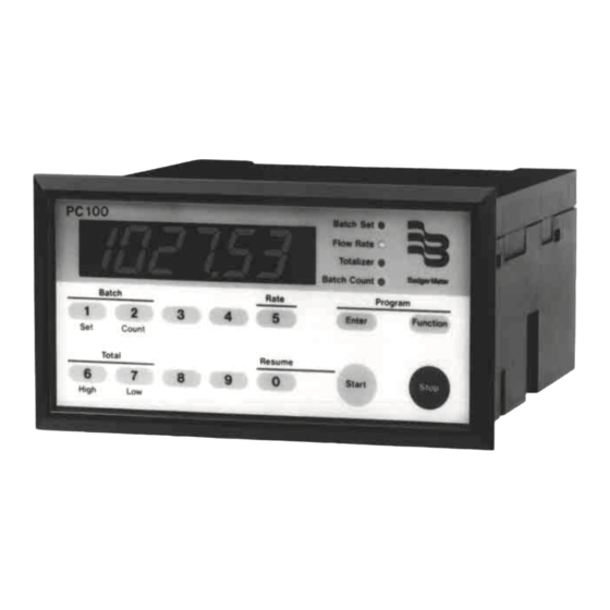
- Page 10 To Program Functions: Press the function key, enter the The PC100 front panel consists of a display of six 7 function number, press the ENTER key to view the present segment LEDs, four yellow LED indicators, and a numeric/ value, change value, and press the ENTER key again to store command keypad.
- Page 11 As we mentioned at the introduction of this manual, many THE PC100 functions are available but only a few must be programmed for the proper operation of the PC100. The functions in this section are not presented in numeric order but instead in lower digits.
-
Page 12: Setup Functions
(day, week, year or shift). If connected to know what your batch is before the next operation, just to terminal #17, a second PC100, it can be used to start press the 1 key and then the ENTER key. - Page 13 #37. If you want the PC100 to register in whole units, you must Connect to a visual or audible alarm to alert you of divide 1 by the unscaled pulses. Program the decimal point irregular flow conditions.
- Page 14 Program a batch value into the PC100 that is larger than the capacity of the vessel that will contain the fluid. Push the START button on the PC100. Press the STOP button when the fluid nears the capacity of the vessel you are filling.
- Page 15 If your operation consists of several batches of the same size, you can program the PC100 to start each batch auto- matically after a preset period of time (0.0 to 999.9 seconds). This is useful in container filling operations.
-
Page 16: Resetting Counters
Use function #52 to reset the totalizer to zero. The 10 digit units per second, minutes or hours. Code 0 is for seconds, totalizer on the PC100 has a capacity to totalize up to 1 is for minutes, and 2 is for hours. To view rate of flow, simply 9,999,999,999 (ten billion.) The totalizer must be reset to... -
Page 17: Serial Communications
I.D. (1 to 99) 3= nothing 3 = INV to each PC100. The I.D. can then be used to channel 4 = C COUNT - B COUNT communications from and to the host controller. - Page 18 This section deals with most of the common problems that representative or call our Industrial Sales Department at you may encounter with the PC100, the possible causes and (414) 355-0400. the recommended remedies. Most of the problems are due to improper wiring and or programming procedures.
- Page 19 ATTN: Customer Service Department “PC100 FOR REPAIR” dure using function #40. Badger Meter Inc. What this will do is put the PC100 into a self test of all 4545 W. Brown Deer Road memories and timers. P.O. Box 245036 During self test all digits and decimal points will light up Milwaukee, WI 53224-9536 in ascending sequence.
- Page 20 Due to continuous research, product improvements and enhancements, Badger Meter reserves the right to change product or system specifications without notice, except to the extent an outstanding bid obligation exists. Please see our website at www.badgermeter.com BadgerMeter,Inc. for specific regions and contacts.
Need help?
Do you have a question about the PC100 and is the answer not in the manual?
Questions and answers