Sign In
Upload
Download
Table of Contents
Contents
Add to my manuals
Delete from my manuals
Share
URL of this page:
HTML Link:
Bookmark this page
Add
Manual will be automatically added to "My Manuals"
Print this page
×
Bookmark added
×
Added to my manuals
Manuals
Brands
Badger Meter Manuals
Controller
ER-420-AC
User manual
Badger Meter ER-420-AC User Manual
Industrial registers, totalizer and rate of flow indicator with 4-20 ma output signal
Hide thumbs
1
2
Table Of Contents
3
4
5
6
7
8
9
10
11
12
13
14
15
16
17
18
19
20
21
22
23
24
25
26
27
28
29
30
31
32
33
34
35
36
37
38
39
40
page
of
40
Go
/
40
Contents
Table of Contents
Troubleshooting
Bookmarks
Table of Contents
Table of Contents
About this Manual
Conventions Used in this Manual
Safety
Warnings
Rules and Precautionary Measures
INTRODUCTION System Description of the ER-420
Operation
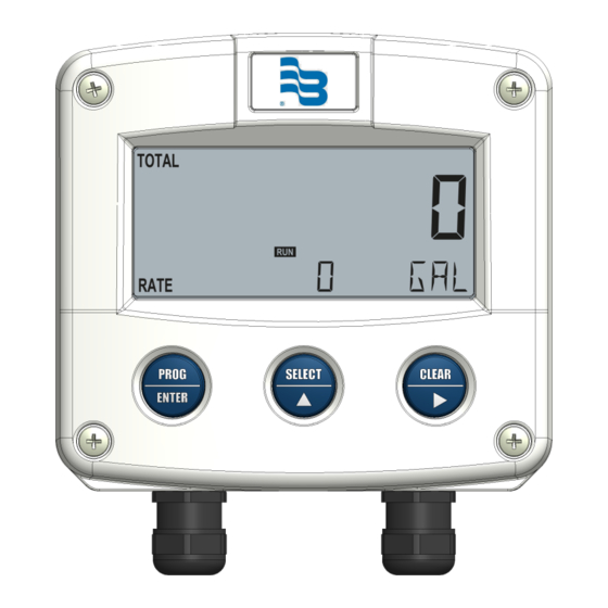
Control Panel
Operator Information and Functions
Configuration
Introduction
Programming Setup Level
Overview of Setup Functions
Details of Setup Functions
Transmitter Pulses Per Unit
Installation
General Directions
Installation Considerations
GRP (Glassfiber-Reinforced Polyamide) Enclosure Dimensions
Installing the Hardware
Industrial Oval Gear Adapter Wiring
Maintenance
General Directions
Repair
Appendix A: Technical Specifications
General
Inputs
Outputs
Operational
Appendix B: Troubleshooting
Your Configuration Settings
Advertisement
Quick Links
1
Control Panel
2
Operation
3
Programming Setup Level
4
General Directions
5
Installation
6
Appendix B: Troubleshooting
Download this manual
Industrial Registers
Models ER-420-AC, ER-420-DC & ER-420-LP
Totalizer and Rate of Flow Indicator with 4-20 mA Output Signal
Users Manual
REG-UM-00018-EN-05 (March 2013)
Table of
Contents
Previous
Page
Next
Page
1
2
3
4
5
Advertisement
Table of Contents
Need help?
Do you have a question about the ER-420-AC and is the answer not in the manual?
Ask a question
Questions and answers
Related Manuals for Badger Meter ER-420-AC
Controller Badger Meter ER-420-LP User Manual
Industrial registers, totalizer and rate of flow indicator with 4-20 ma output signal (40 pages)
Controller Badger Meter PC100 Installation And Operation Manual
(20 pages)
Controller Badger Meter PC200 User Manual
Industrial process controller (36 pages)
Controller Badger Meter CB-30 User Manual
Batch controller (16 pages)
Controller Badger Meter MDS2000 User Manual
Oil management system (66 pages)
Controller Badger Meter Impeller Data Industrial 3100 Series User Manual
Dual channel monitor / controller / transmitter (28 pages)
This manual is also suitable for:
Er-420-dc
Er-420-lp
Table of Contents
Print
Rename the bookmark
Delete bookmark?
Delete from my manuals?
Login
Sign In
OR
Sign in with Facebook
Sign in with Google
Upload manual
Upload from disk
Upload from URL


Need help?
Do you have a question about the ER-420-AC and is the answer not in the manual?
Questions and answers