
Related Manuals for Health in motion INSPIRE DUAL AB BACK


Summary of Contents for Health in motion INSPIRE DUAL AB BACK
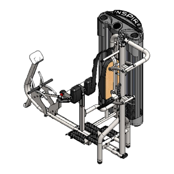
- Page 1 ASSEMBLY & OPERATION MANUAL DUAL Ab Back RECORD SERIAL NUMBER HERE www.inspirefitness.com by Health In Motion LLC 8-28-18...
- Page 2 CONGRATULATIONS… You’ve just taken the first step to a healthier and stronger body. This Dual Ab Back machine by Inspire offers the key to unlocking your body’s potential. Regular strength training on a multi-gym has been shown to deliver a host of benefits including: increased muscle tone, decreased body fat, improved energy levels, a reduction in stress, and improved cardiac output.
-
Page 3: Table Of Contents
TABLE OF CONTENTS Section Description……………………………………………………. Page Important Safety Instructions………………………………………. Tools Required………………………………………………………………… Parts & Hardware List……………………………………………………. Cable Charts…………….……………………………………………………. Assembly Instructions……………………………………………………. Decal Reference……………………………………………………………… Decal Placement…………………………………………………………….. Training Tips…………………………………………………………………… General Maintenance Information…….…………………………… Maintenance Schedule…….……………………………………………… Limited Warranty…………………………………………………………….. -
Page 4: Important Safety Instructions
IMPORTANT SAFETY INSTRUCTIONS Please read this entire manual and familiarize yourself with all decals and warnings before using this Dual Ab Back machine. • WARNING! It is necessary to inspect this Dual Ab Back machine regularly to maintain safety and proper function. Please use the maintenance schedule included towards the back of this manual. -
Page 5: Parts & Hardware List
DUAL AB BACK PARTS & HARDWARE LIST Item Parts Description Qty Qty Rec'd Item Hardware Description Qty Qty Rec'd Main Frame M10 x 25 Hex Bolt Guide Cable Support M10 x 95 Hex Bolt Upright 1 M10 x 75 Hex Bolt Base Frame M6 x 12 Button Head Bolt Top Weight/Selector Stem... -
Page 6: Cable Charts
Page 3... -
Page 7: Assembly Instructions
ASSEMBLY INSTRUCTIONS Page 4... - Page 8 Step 1 Step 2 2 - M10 x 25 Hex Bolts 2 - M10 x 95 Hex Bolts 4 - M10 x 75 Hex Bolts 6 - M10 Flat Washers 8 - M10 Flat Washers 2 - M10 Locknuts 4 - M10 Locknuts Guide Cable Support Main Frame...
- Page 9 Step 4 2 - M10 x 20 Flat Head Bolts 2 - M10 x 75 Button Head Bolts 4 - M10 Flat Washers 2 - M10 Locknuts Upright 2 Rear Legs Main Frame Step 5 Base Frame 2 - M10 x 70 Hex Bolts 1 - M10 x 125 Hex Bolts 6 - M10 Flat Washers 3 - M10 Locknuts...
- Page 10 Step 6 4 - M10 x 75 Button Head Bolts 8 - M10 Flat Washer 4 - M10 Locknuts 4 - M8 x 20 Button Head Bolts 4 - M8 Flat Washer Inner Foot Plate Base Frame Outer Foot Plate Step 6: Attach the Inner and Outer Foot Plate to 4 - M10 x 75 Button Head Bolts Base Frame using:...
- Page 11 Step 8 Step 7 1 – M8 x 16 Cap Screw 2- M10 x 25 Hex Bolts 2 - M10 x 20 Flat Head Bolts 4- M10 Flat Washers Hip Pad Mount 2- M10 Locknuts Install M8 Cap Screw into Stem after Stem is fully Main Frame inserted...
- Page 12 Step 9 M8 x 20 Hex Bolt 1 - M10 x 75 Hex Bolt 2 - M10 x 90 Hex Bolts 6 - M10 Flat Washers Upper Pulley 3 - M10 Locknuts Mount, Left 1 - M8 x 20 Hex Bolt 1 - M8 Flat Washer Main Frame Front of weight plate has recessed...
- Page 13 M8 x 20 Hex Bolt Step 10 1 - M10 x 75 Hex Bolt Front of weight plate has recessed 2 - M10 x 90 Hex Bolts area for the number sticker 6 - M10 Flat Washers 3 - M10 Locknuts 1 - M8 x 20 Hex Bolt 1 - M8 Flat Washer Upper Pulley...
- Page 14 Step 12 Step 13 Step 11 8 – M8 x 12 Button Head Bolts 2 - M10 x 20 Hex Bolts 4 - M10 x 75 Hex Bolts 8 – M8 Flat Washers 2 - M10 Flat Washers 8 - M10 Flat Washers 4 - M10 Locknuts Attachment Arm 2A Main Base...
- Page 15 Step 15 Cable Connector Cable Retainer Cable Routing Inspect Hole Pulley 1 Cable Pulley 2 Jam Nut AB BACK CABLE CHART AB BACK CABLE CHART Pulley 5 Pulley 4 Selector Stem Remove Jam Nut and Slotted Bolt from Cable before installing Cable Assembly Thread bolt completely into selector Remove Jam Nut and Slotted Bolt from stem and tighten jam nut...
- Page 16 Swivel Step 16 Pulley Back Cable Routing Cable Retainer 2 “U” Bracket Assembly Pulley 11 Pulley 10 Pulley 8 Pulley 7 Cable Connector Inspection Hole Weight Slotted Cable Bolt Cable Back Cable Cable Jam Nut Selector Stem Thread Bolt completely into Selector Pulley 9 Pulley 8 Pulley 7...
- Page 17 Back Pad Adjustment Arm Step 17 2 - M10 x 20 Button Head Bolts 2 - M10 Flat Washers Back Pad Arm 2 Back Pad Adjustment Arm NOTE: Top Flat Head Bolt does not use Washer or Locknut Step 18 3 - M8 x 20 Flat Head Bolts 2 - M8 Flat Washers 2 - M8 Locknuts...
- Page 18 Step 21 Ab Back Strap Step 19 Attach Ab Back Strap 1 - M10 x 80 Hex Bolt 1 - M10 x 20 Hex Bolt 2 - M10 Flat Washers Back Pad Step 20 4 - M10 x 20 Button Head Bolts 4 - M10 Flat Washers Back Pad Mount Hip Pad...
- Page 19 Cable Connector Inspection Hole Cable Bolt Step 22: At this point it is necessary to seat the cables. Start by verifying that cables are centered in the grooves of all pulleys. Next, select a weight you can comfortably handle on the Ab Back. Pull the Ab Strap and lightly bounce the weight up and down for about 5 seconds and then repeat for the Revolving Straight Bar.
- Page 20 Step 24 Insert Shroud into Metal Pieces Upper Metal Shroud Fabric Shroud Lower Metal Shroud Step 24: To install Fabric Shroud, start from one end of the Lower Metal Shroud and insert the Fabric Shroud inwards as shown. Make sure to have the same orientation as shown or else the fabric shroud will be installed backwards.
- Page 21 Step 26 3 - M10 x 50 Fully Threaded Hex Bolts 3 - M10 Flat Washers Step 25 1 - M10 x 25 Button Head Bolt 2 - M10 x 70 Hex Bolts 3 - M10 Flat Washers Step 25: Attach the Lower Metal Shroud to the Upright 1 1 –...
- Page 22 Step 27 10 - M6 x 12 Button Head Bolts 10 - M6 Flat Washer Right Metal Shroud Plate Left Metal Shroud Plate Upright 1 Step 27: Attach Right and Left Metal Shroud Plates to 10 – M6 x 12 Button Head Bolts Upright 1 using: 10 –...
- Page 23 Step 28 6 - M8 x 12 Button Head Bolts 6 - M8 Flat Washers Metal Shroud Placard, Right Upper Metal Shroud Metal Shroud Placard, Left Step 28: Attach the Metal Shroud Placard to the 6 – M8 x 12 Button Head Bolts Upper Metal Shroud using: 6 –...
- Page 24 Rubber tablet holder only fits one way. Make sure the outer edge of the tablet holder sits flat against the Cap surface. Step 29 1 - M8 x 12 Button Head Bolt 1 - M8 Flat Washer 2 - M10 x 25 Button Head Bolts 2 - M10 Large OD Flat Washers Rubber Cup Rubber Tablet...
-
Page 25: Decal Reference
DECAL REFERENCE 877-738-1729 7,905,818; 8,096,929; 8,870,718; 9,067,100; 9,302,139 Page 22... - Page 26 DECAL REFERENCE Page 23...
-
Page 27: Decal Placement
DECAL PLACEMENT Globe Logo Label (50mm) Round “INSPIRE” logo Placard Label, Left “PINCH POINT “ Placard Label, Right Label (25 x 40) Weight # labels (1 – 11), included with manual. Silver #’s on black “NOTICE” Label background. on side of Rear (18 x 25) Upright. -
Page 28: Training Tips
Training Tips CONSULT A PHYSICIAN BEFORE STARTING ANY EXERCISE PROGRAM 1. Always warm up before you start weight training. This helps get your muscles warm and prevents injury. You can warm up with light cardio or by doing a light set of each exercise before going to heavier weights. -
Page 29: General Maintenance Information
GENERAL MAINTENANCE INFORMATION • Periodically inspect the cables for splitting, cracking or fraying. Also, watch for bulging or flat areas in the cable. • Immediately replace cables at the first signs of damage or wear. Never use equipment with damaged or worn cables. •... -
Page 30: Maintenance Schedule
MAINTENANCE SCHEDULE COMMERCIAL/ HOME ROUTINE ENTRY DATE LIGHT COMMERCIAL MAINTENANCE MAINTENANCE Inspect: Links, Pull Pins, Spring Clips, DAILY WEEKLY Swivels, Weight Stack Pins. DAILY WEEKLY Clean: Upholstery. Inspect: Cables and DAILY WEEKLY their Fittings for wear or looseness. Inspect: Tautness of DAILY WEEKLY all Shrouds. -
Page 31: Limited Warranty
In Motion reseller. This Warranty does not extend to any Product that has been damaged or rendered defective; (a) as a result of accident, misuse, or abuse; (b) by the use of parts not manufactured or sold by Health In Motion; (c) by modification of the Product;...
Need help?
Do you have a question about the INSPIRE DUAL AB BACK and is the answer not in the manual?
Questions and answers