Table of Contents
Advertisement
Quick Links
Advertisement
Table of Contents

Subscribe to Our Youtube Channel
Related Manuals for Scotchman SHEARMASTER 610


Summary of Contents for Scotchman SHEARMASTER 610
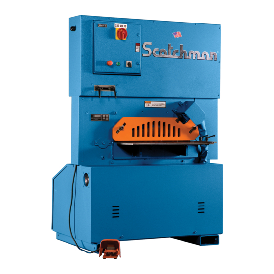
- Page 1 You have downloaded a manual for our Model SHEARMASTER 610 Ironworker.
- Page 2 MODEL SHEARMASTER 24" PLATE SHEAR SEPTEMBER 2021...
-
Page 3: Table Of Contents
TABLE OF CONTENTS SECTION DESCRIPTION PAGE # INTRODUCTION SAFETY PRECAUTIONS WARRANTY WARNING LABELS INSTALLATION AND SET-UP 7-13 Physical Dimensions Machine Moving Procedures Physical Inspection Electrical Requirements Machine Start-Up Machine Stroke Inspection and Adjustment MAINTENANCE 14-16 Lubrication Scheduled Maintenance MACHINE OPERATION 16-20 Bar Shear Operation 6.2A... - Page 4 TABLE OF CONTENTS SECTION DESCRIPTION PAGE # Hydraulics Seal Replacement-Cylinder PARTS LISTS 30-51 Shear Arm Assembly Shear Table Assembly Upper Panel Sheet Metal Electrical Unit Power Unit Hold Down Assembly Cylinder Assembly Material Conveyor 9.10 48" Electric Back Gauge 9.11 Tiger Stop Adapter 9.12 Electrical &...
-
Page 5: Introduction
1.0 INTRODUCTION The Scotchman 610 Shear is a versatile, shearing machine engineered for trouble free operation. The design of the machine combines simplicity of operation with smooth, full stroke control. The ability of the operator to control the machine’s direction of movement at any point in the stroke, (stop, jog or reverse), gives the Scotchman Shear a tremendous advantage over mechanical shears. -
Page 6: Warranty
2.1 WARRANTY Scotchman Industries, Inc. will, within three years of the date of purchase, replace F.O.B. the factory or refund the purchase price for any goods which are defective in materials or workmanship, provided the buyer , at the seller’s option, returns the defective goods freight and delivery prepaid to the seller, which... -
Page 7: Warning Labels
3.0 WARNING LABELS ITEM PART # DESCRIPTION 003100 MAIN WARNING LABEL CAPACITY LABEL 003120 DANGER: VOLTAGE 003105 FINGERS BEYOND (SHEAR) FIGURE 1 PAGE 6... -
Page 8: Installation And Set-Up
4.0 INSTALLATION AND SET-UP Ö CAUTION: THIS SECTION DISCUSSES INSTALLATION AND SET-UP PROCEDURES. PLEASE READ THOROUGHLY BEFORE OPERATING THIS MACHINE. 4.1 PHYSICAL DIMENSIONS INCHES F. Floor To Bottom Of Base 3-1/2 G. Floor To Bar Shear 81.2 K. Height L. Width 33.5 N. -
Page 9: Machine Moving Procedures
4.2 MACHINE MOVING PROCEDURES Ö CAUTION: BE SURE THAT ANY LIFTING DEVICE HAS ADEQUATE CAPACITY BEFORE ATTEMPTING TO MOVE THIS MACHINE. THIS MODEL WEIGHS 3,0100 LB. (1,368 KG.). IT IS DESIGNED TO BE MOVED BY A FORKLIFT OR AN OVERHEAD CRANE. THERE ARE FORKLIFT SLOTS DESIGNED INTO THE BASE OF THE MACHINE FOR THIS PURPOSE. -
Page 10: Physical Inspection
4.3 PHYSICAL INSPECTION Any damage to the machine during shipment should be reported to the delivery carrier immediately. A damage report must be made so that a claim can be placed. The carrier is responsible for shipping damage, but it is the customer’s responsibility to immediately report damages, external or internal. After the machine has been located, remove the side shrouds and inspect the interior of the machine for possible shipping damages. -
Page 11: Electrical Requirements
4.4 ELECTRICAL REQUIREMENTS Ö CAUTION: TO PREVENT DAMAGE TO THE MOTOR AND DANGER TO THE OPERATOR, ALL ELECTRICAL CONNECTIONS SHOULD BE MADE BY A LICENSED ELECTRICIAN. All machines are wired for three phase electrical power unless otherwise specified by customer. The sup- ply voltage should be (+ or -) 10% of the motor voltage rating, to insure satisfactory machine perfor- mance. - Page 12 FIGURE 4 PAGE 11...
-
Page 13: Machine Start-Up
4.5 MACHINE START-UP BEFORE STARTING THIS MACHINE, TAKE TIME TO THOROUGHLY REVIEW THE VHS SAFETY TAPE OR SAFETY CD AND THE OPERATOR’S MANUAL. This machine is equipped with a lock-out, disconnect switch as standard equipment. We strongly urge you to follow the OSHA directive CFR-1910.147 (effective 09-01-90) regarding lock-out, tag-out proce- dures. - Page 14 FIGURE 5 PAGE 13...
-
Page 15: Maintenance
5.0 MAINTENANCE The Scotchman Shear is an exceptionally rugged machine designed for long life with a minimum amount of maintenance. A regular program of servicing will extend the life of the machine and prevent costly down time. 5.1 LUBRICATION IMPORTANT: Before operating the SHEARMASTER 610, apply oil to the bar shear blades. -
Page 16: Scheduled Maintenance
GREASE POINTS FIGURE 6 5.2 SCHEDULED MAINTENANCE A program of scheduled maintenance should be set up and documented according to your application and the frequency you use this machine. The following is a list of some important items that should be included in a scheduled maintenance program. -
Page 17: Machine Operation
HOLD-DOWN DEVICE TO ITS DOWN POSITION. When using the bar shear on your Scotchman Ironworker, always use the hold-down device. Never put any part of your body between the hold-down and the material to be sheared. A maximum clearance of 1/8"... - Page 18 BAR SHEAR GUIDE INSTRUCTIONS SHEARMASTER 610 STOP PIN USE OUTER STOP PIN HOLES STOP PIN HOLE FOR STORAGE OF GUIDE WHEN NOT BEING USED USE INNER STOP PIN HOLES WITH GUIDE ORIENTATED AS SHOWN FOR 90° CUTS ON LEFT SIDE OF TABLE...
- Page 19 THE BASIC METHOD OF OPERATING THE BAR SHEAR CONSISTS OF THE FOLLOWING STEPS: Place the material to be sheared between the shear blades. Adjust the hold-down device down until it is 1/8 to 1/4 of an inch above the material to be sheared. REFER TO SECTION 6.2A.
-
Page 20: A Shear Blade Adjustment
6.2A SHEAR BLADE ADJUSTMENT FIGURE 8 o To set the blades, lower the arm so that the upper blade passes the lower blade. (If fitting new or re-ground blades, ensure that the lower blade is fully adjusted away from the upper blade before lowering the arm.) o Switch off the machine. -
Page 21: B Shear Arm Adjustment
6.2B SHEAR ARM ADJUSTMENT For parts identification, SEE FIGURE 9 BELOW. Ö CAUTION: BEFORE MAKING ANY ADJUSTMENTS, THE BAR SHEAR BLADES MUST BE BACKED AWAY FROM EACH OTHER. The adjustment of the shear arm is maintained by three adjustment bolts. To adjust the arm, loosen the lock nuts on the three adjusting bolts. -
Page 22: Electric Back Gauge
7.0 ELECTRIC BACK GAUGE 7.1 SETTING THE LENGTH STOP TO THE MACHINE The length stop has to be set to suit the model of the machine. The following steps outline this simple procedure. Secure the length stop assembly to the machine. Set the slide block on the bar so that the probe (A) is a set distance from the lower blade, say 10"... -
Page 23: Using Touch And Cut
The "Touch and Cut" can be positioned anywhere along the length of the shear. It will increase produc- tivity, particularly when cropping large batches. Do not be tempted to get that last length of cut from the bar if it is not correctly positioned under the hold down. This may cause serious damage to the machine. On the length left over, mark the desired length and crop off the off-cut. - Page 24 FIGURE 13 PAGE 23...
-
Page 25: Trouble Shooting Guide
8.0 TROUBLE SHOOTING GUIDE 8.1 ELECTRICAL TROUBLE SHOOTING - MOTOR Ö CAUTION: ALL ELECTRICAL WORK PERFORMED ON THE 610 SHEAR SHOULD BE PER- FORMED BY A QUALIFIED ELECTRICIAN. A. MOTOR WILL NOT RUN: 1. Check the selector switch. The machine will not start unless the selector switch is in the START po- sition. - Page 26 5. Check the limit switches. (For procedures, REFER TO SECTION 8.2 ON THE FOLLOWING PAGE.) 6. No power from the transformer: Check the voltage across the transformer’s secondary terminals. It should read 110 to 120 volts. 7. The solenoid on the control valve is not functioning. REFER TO SECTION 8.3. 8.
-
Page 27: Limit Switch Inspection Procedure
8.2 LIMIT SWITCH INSPECTION PROCEDURE To determine if the limit switches are functioning properly, move the limit switches out to their farthest position. Place the selector switch in the START position and power the machine. Place the selector switch in the MANUAL position. While holding the foot pedal, use a pencil or similar device and depress the limit switch that the meter ing boss is traveling towards. -
Page 28: Hydraulics
shifting the spool, turn the machine on and try it again. If the machine now operates, the hydraulic oil and filter should be changed. A defective coil on the control valve: The coils can be checked using an Ohm meter. The wires to the coils must be disconnected. -
Page 29: Seal Replacement-Cylinder
8.5 SEAL REPLACEMENT - CYLINDER For parts identification, REFER TO FIGURE 11 ON THE FOLLOWING PAGE. 1. After removing the cylinder from the machine, lay it on its side, with the ports down, and allow the hydraulic fluid to drain. 2. - Page 30 025106 - SEAL KIT FOR 025105 CYLINDER ITEM QTY PART # DESCRIPTION Please Note that these 025105.1 WEAR RING 025105.10 Part Numbers are for BARREL 025105.2 BACK-UP RING ASSEMBLY REFERENCE ONLY!! 025105.3 O-RING (large) 025105.4 O-RING (small) 025105.5 WEAR RING See next page for for 025105.8 025105.6...
- Page 31 ITEM QTY PART # DESCRIPTION Please Note that these 025105.1 WEAR RING Part Numbers are for 025105.2 BACK-UP RING CUTAWAY VIEW 025105.3 O-RING (large) REFERENCE ONLY!! 025105.4 O-RING (small) See previous page for 025105.5 WEAR RING 025105.6 LOADED U-CUP the Exploded View. 025105.7 ROD WIPER ITEM'S 1-7 ARE INCLUDED IN SEAL KIT P/N 025106...
- Page 32 SHEARMASTER WITH OPTIONAL 5ft. ROLLER CONVEYOR - P/N 026976 STANDARD FEATURES : Hydraulic Hold-Down - Electric Back Gauge - Electric Stroke Control - Electric Foot Pedal Two-Stage Hydraulic Pump - 10 hp Motor - Forklift Accommodations Warranty: Three Years on Parts MADE IN THE USA PAGE 29B...
-
Page 33: Parts Lists
9.0 PARTS LISTS The Following Sections Contain Parts Lists And Drawings. P For Your Convenience, Always Give Your Complete Serial Number When Ordering Parts. 9.1 SHEAR ARM ASSEMBLY ITEM PART # DESCRIPTION 215014 M-12 Hex Nut 017486 Metering Boss 221328 M-12 x 90 SHCS 017485 Main Bushing... - Page 34 FIGURE 14 PAGE 31...
-
Page 35: Shear Table Assembly
9.2 SHEAR TABLE ASSEMBLY ITEM PART # DESCRIPTION 080063 Handles 025705 Guide 026618 Tee Nut 220029 M-10 x 35 BHCS 210012 M-10 Jam Nut 230210 M-10 x 30 FSHCS 026698 Rest Buttons 080430 Table 080435 Complete Table FIGURE 15 PAGE 32... -
Page 36: Upper Panel
9.3 UPPER PANEL ITEM PART # DESCRIPTION 080061 Handles 004087 Pointers 220014 M-6 x 10 BHCS 017496 Stroke Plate 004086 Limit Switch Mounts 562113 Limit Switches 073450 M-4 x 6 SHCS 017493 Top Shroud (Front) 090385 Light 220020 M-6 x BHCS FIGURE 16 PAGE 33... -
Page 37: Sheet Metal
9.4 SHEET METAL ITEM PART # DESCRIPTION 017490 Front Shroud 017491 Rear Shroud 017499 Slug Ramp 017503 Shear Door 017496 Stroke Plate 017500 Cylinder Cover (Hold Down) 017494 Cylinder Cover 017493 Upper Panel (Front) 017492 Upper Panel (Rear) 017495 End Cover 220014 M-6 x 10 BHCS PAGE 34... - Page 38 FIGURE 17 PAGE 35...
-
Page 39: Electrical Unit
9.5 ELECTRICAL UNIT ITEM PART # DESCRIPTION 011861 Transformer 011852 Primary Fuse 011853 Secondary Fuse 011862 Emergency Stop Button 011867 Emergency Stop Switch 013219 Contactor (1PH) 011863 Contactor (3PH) 011869 Start Button 011874 Start Switch 562453 Foot Switch 011753 Cord (Foot Switch) 562452 Micro Switch (Foot Switch) 011868... - Page 40 FIGURE 18 PAGE 37...
-
Page 41: Power Unit
9.6 POWER UNIT ITEM PART # DESCRIPTION Return Line 014115 014210 Fan Cord 006630 Filter Breather Cap 017531 Hold Down Cylinder 003734 Pressure Hose 003731 Pressure Hose 025105 Cylinder 013501 Motor Assembly (220-1PH) 013508 Motor Assembly (230-3PH) 013509 Motor Assembly (460-3PH) 017552 Pressure Hose 017553... - Page 42 FIGURE 19 PAGE 39...
-
Page 43: Hold Down Assembly
9.7 HOLD DOWN ASSEMBLY ITEM PART # DESCRIPTION 201610 M-16 x 25 DIN933 HHCS 113017 M-16 Washer 017502 Hold Down Plate 221315 M-12 x 40 SHCS 017505 Hold Down Guide 017531 Hold Down Cylinder FIGURE 20 PAGE 40... -
Page 44: Cylinder Assembly
9.8 CYLINDER ASSEMBLY ITEM PART # DESCRIPTION 016630 2-1/2" Snap Ring 025071 Cylinder Anchor Pin 025105 Cylinder 017510 Clevis Pin 016620 Snap Ring 017507 Cylinder Clevis FIGURE 21 PAGE 41... - Page 45 9.9 CONVEYOR SYSTEM ITEM PART #'S DESCRIPTION 216015 Flange Nut 213012 M-10 Flat Washer 026955 Bump Roller Mount 026962 Bump Roller 016402 3/4 Snap Ring 201212 M-10 x 35 HHCS 026960 Bump Roller Assembly 026965 Bump Roller Mount 026905 Rollers 026972 Track Assembly 026986...
- Page 46 FIGURE 22 PAGE 43...
-
Page 47: 48" Electric Back Gauge
9.10 48" ELECTRIC BACK GAUGE ITEM PART # DESCRIPTION 025338 Stop 208012 M-10 Hex Nut 201220 M-10 x 50 HHCS 025332 Spring 025335 Spring Plate 025323 Housing 218023 M-6 x 12 SS 218022 M-4 x 10 SHCS 562113 Limit Switch 073450 M-4 x 16 SHCS 220010... - Page 48 FIGURE 23 PAGE 45...
-
Page 49: Tiger Stop Adapter
9.11 TIGER STOP ADAPTER ITEM PART # DESCRIPTION 028451 Stand (Includes 2 & 3) 049217 Foot 208024 Hex Nut 028456 Mounting Bracket 028422 Tee Nut 073420 M-8 x 16 SHCS 214011 M-8 Flat Washer 221115 M-8 x 20 SHCS 208010 M-8 Hex Nut 028450 Complete Stand Assembly... - Page 50 FIGURE 24 PAGE 47...
-
Page 51: Electrical & Hydraulic Schematics
9.12 ELECTRICAL & HYDRAULIC SCHEMATICS FIGURE 25 PAGE 48... - Page 52 FIGURE 26 PAGE 49...
- Page 53 FIGURE 27 PAGE 50...
- Page 54 1 PHASE 3 PHASE INCOMING POWER INCOMING POWER DISCONNECT DISCONNECT 13 NO 13 NO CONTACTOR CONTACTOR CONTACTOR CONTACTOR 14 NO 14 NO _OL_ _OL_ OVERLOAD OVERLOAD OVERLOAD OVERLOAD TEST TEST ZB32-32 ZB32-32 RESET RESET SET TO SET TO MOTOR MOTOR TO MOTOR TO MOTOR FIGURE 28...
- Page 55 All New Machines Now Have The 250 KVA Transformer as Standard Equipment. WITH WORK LIGHT HIGH VOLTAGE C0NNECTION 250 KVA ( 440-480 VOLT 3PH ) PRIMARY SIDE FUSE FUSE H1-H2 H1-H3 H1-H4 H1-H5 EATON 250 VA CO250E6U XF-X2 XF-X3 XF-X4 FUSE SECONDARY SIDE WHITE...
Need help?
Do you have a question about the SHEARMASTER 610 and is the answer not in the manual?
Questions and answers