
Related Manuals for Scotchman Porta-Fab 45


Summary of Contents for Scotchman Porta-Fab 45
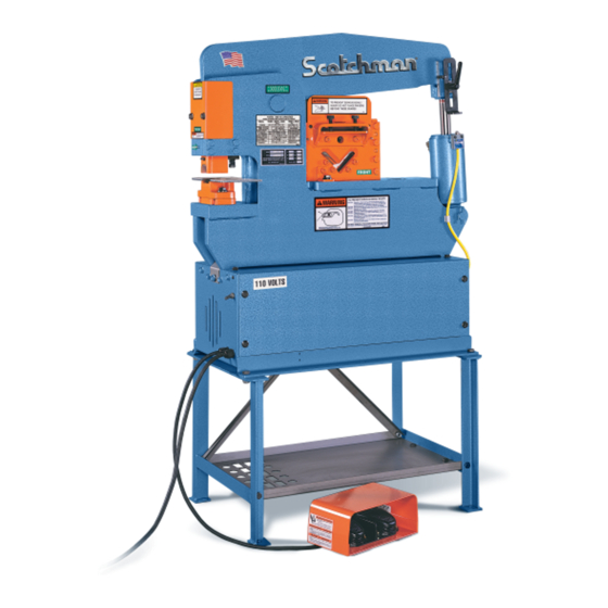
- Page 1 You have downloaded a manual for our Model Porta-Fab 45 Ironworker. This manual does not include all of the optional tooling for this machine. If you would like a tooling manual, please download the #20 Tooling Manual. MADE IN THE USA...
- Page 2 MODEL PORTA-FAB 45 TON IRONWORKER JANUARY 2022 SCOTCHMAN INDS. - 180 E US HWY 14 - PO BOX 850 - PHILIP, SD 57567 Call: 1-800-843-8844...
-
Page 3: Table Of Contents
TABLE OF CONTENTS SECTION DESCRIPTION PAGE # INTRODUCTION SAFETY PRECAUTIONS Warranty WARNING LABELS INSTALLATION & SET UP 8-11 Physical Dimensions Machine Moving Procedures Physical Inspection Electrical Requirements Machine Start-up MAINTENANCE 13-15 Lubrication Scheduled Maintenance MACHINE OPERATION 16-25 Punch Operation Three in One Shear OPTIONAL TOOLING 26-49 Rod Shear... -
Page 4: Introduction
The ability of the operator to control the machine’s direction of movement at any point in the stroke, (i.e. stop, jog or reverse) gives the SCOTCHMAN IRONWORKER a tremendous advantage over mechanical ironworkers. There is no chance of the SCOTCHMAN IRONWORKER being accidentally tripped. -
Page 5: Safety Precautions
2.0 SAFETY PRECAUTIONS The operators of this machine must be qualified and well trained in the operation of the machine. The operators must be aware of the capacities of the machine and the proper use of the hold-down devices, strippers and guards provided with the machine. All of the guards, adjustable restrictors and awareness barriers must be installed on the machine and kept in good working order. -
Page 6: Warranty
2.1 WARRANTY SCOTCHMAN INDUSTRIES, INC. will, within three years of the date of purchase, replace F.O.B. the factory or refund the purchase price for any goods which are defective in materials or workmanship, provided the buyer returns the warranty registration card within thirty (30) days of the purchase date and, at the seller’s option, returns the defective goods freight and delivery prepaid to the seller, which... -
Page 7: Warning Labels
PUNCH & DIE WARNING 019105 DECAL "GREASE POINT" 012372 PORTA-FAB CAPACITY DECAL 019127 US FLAG DECAL 019103 DECAL "LUBRICATE" 010115 15" SCOTCHMAN DECAL 019300 RIGHT HAND RULE 12" 003100 LARGE SAFETY GLASSES 019100 U.S. DATA PLATE 093001 110V STICKER 019120... - Page 8 FIGURE 1 Page 7...
-
Page 9: Installation & Set Up
4.0 INSTALLATION AND SET-UP CAUTION: THIS SECTION DISCUSSES INSTALLATION AND SET-UP PROCEDURES. PLEASE READ ALL SECTIONS OF THIS MANUAL THOROUGHLY BEFORE OPERATING THIS MACHINE. 4.1 PHYSICAL DIMENSIONS WITHOUT STAND WITH STAND INCHES INCHES Floor To The Top Of Die Holder 22.04 55.98 39.54... - Page 10 WITHOUT STAND 012351 012351 Tool Tool 38.13 21.45 22.04 19.20 38.12 20.00 WITH STAND 012351 012351 Tool Tool 4.25 55.63 39.54 36.70 38.95 20.00 Page 9 FIGURE 2...
-
Page 11: Machine Moving Procedures
4.2 MACHINE MOVING PROCEDURES CAUTION: BE SURE THAT ANY LIFTING DEVICE HAS ADEQUATE CAPACITY BEFORE ATTEMPTING TO MOVE THIS MACHINE. The weight of this machine is 605 pounds (274.42 kg) without the optional stand and 635 pounds (288.03 kg) with the stand. FIGURE 3 ON THE FOLLOWING PAGE DEMONSTRATES THE USE OF AN OVERHEAD LIFT OR A FORK LIFT. - Page 12 Punch half holes, punch or shear unknown materials, side load press brakes. SAFETY GLASSES REQUIRED WHEN OPERATING OR OBSERVING THIS MACHINE DO NOT REMOVE THIS SIGN FROM THIS MACHINE 003100 FOR MORE INFORMATION CONTACT SCOTCHMAN INDUSTRIES INC. 1-800-843-8844 REV. 0310 WITHOUT OPTIONAL STAND 012351 Tool...
-
Page 13: Electrical Requirements
4.4 ELECTRICAL REQUIREMENTS CAUTION: TO PREVENT DAMAGE TO THE MOTOR AND DANGER TO THE OPERATOR, ALL ELECTRICAL CONNECTIONS SHOULD BE MADE BY A LICENSED ELECTRICIAN. A 10 foot (3 meter) cord is provided with this machine. The plug you install on the cord must have a minimum rating of 30 amps. -
Page 14: Maintenance
5.0 MAINTENANCE The Scotchman Ironworker is an exceptionally rugged machine designed for long life with a minimum amount of maintenance. A regular program of servicing will extend the machine's life and prevent costly downtime. 5.1 LUBRICATION IMPORTANT: Before operating the Porta-Fab Ironworker, apply oil to the THREE IN ONE TOOL blades and the punch and die. -
Page 15: Scheduled Maintenance
5.2 SCHEDULED MAINTENANCE A program of scheduled maintenance should be set up and documented according to your application and the frequency you use this machine. The following is a list of important items that should be included in a scheduled maintenance program: EVERY 250 HOURS OR THREE MONTHS: Check the clearance between the punch barrel (A) and the punch barrel guide (B). - Page 16 FIGURE 4 Page 15...
-
Page 17: Machine Operation
6.0 MACHINE OPERATION 6.1 PUNCH OPERATION ALWAYS WEAR SAFETY GLASSES. THE FIRST AND MOST IMPORTANT PROCEDURE IS THE PROPER METHOD OF INSTALLING AND ALIGNING PUNCHES AND DIES. WARNING: FAILURE TO PROPERLY ALIGN PUNCHES AND DIES CAN CAUSE SERIOUS INJURY TO PERSONNEL AND/OR DAMAGE TO EQUIPMENT. - Page 18 ALIGNMENT AND REMOVAL OF PUNCHES AND DIES. REFER TO FIGURE 5 ON THE PRECEDING PAGE. With the punch in the down position and the arm up, turn the machine’s electrical power OFF. Remove the stripper (B) by pressing down on the tab (A) and pulling the stripper toward you. Loosen and remove the bolts (G) holding the die holder (C) and remove the die holder (C) and spacer (D).
- Page 19 Align the punch to the die so that there is equal clearance on all sides of the punch in the die. Insert and tighten both the die holder bolts (G) firmly. Check to be sure that the punch and die are still in alignment. Realign, if necessary. Replace the stripper (B).
- Page 20 PUNCHING ANGLE IRON. This machine is designed to punch angle iron with the leg down. If the application requires punching closer to the web than the standard dies allow, special offset dies are available. FOR ADDITIONAL INFORMATION ON PUNCHES AND DIES, SEE THE TOOLING MANUAL. CAUTION: PUNCHING ANGLE IRON WITH THE LEG UP WILL CAUSE DAMAGE TO THE PUNCH RETAINING NUT.
- Page 21 TONS REQUIRED PER HOLE TO PUNCH MILD STEEL HAVING 65,000 PSI TENSILE STRENGTH 3/16 5/16 7/16 9/16 11/16 13/16 15/16 HOLE DIAMETER .1875 .250 .3125 .375 .4375 .500 .5625 .625 .6875 .750 .8125 .875 .9375 1.00 .125 METAL THICKNESS P R E S S U R E I N T O N S GAUGE INCHES .015...
- Page 22 Under normal punching conditions, a punch will use a corresponding die stamped the same size. A 3/8 inch punch will use a die stamped 3/8 inch. All Scotchman #20K punches and dies are stamped withthe size. All dies have a larger hole in the bottom side for slug relief.
- Page 23 MAINTAIN SUFFICIENT MATERIAL BETWEEN THE PUNCHED HOLE AND THE EDGE OF THE WORKPIECE. The edge of the punch should clear the edge of the workpiece by a distance equal to the thickness of the material. Any edge distance less than this will result in a deformed workpiece. DO NOT WORK WITH DULL OR DAMAGED TOOLING.
- Page 24 BEST IN THE BUSINESS WARRANTY MADE IN THE USA...
- Page 25 6.2 THREE IN ONE COMBINATION TOOL The Three In One shear is a component tool designed to shear angle iron, round stock and plate. It installs on the tool table and has a maximum capacity of 3" x 3" x 5/16" inch (76x76x8mm) mild steel angle iron, 3/4"...
- Page 26 THE THREE IN ONE SHEAR MOUNTS ON THE TOOL TABLE AS SHOWN ON PREVIOUS PAGE. The arm must be in the up position. Slide the tool under the arm with the Warning Label and the (2) thumb screws facing the operator's side of the machine.
- Page 27 6.2B THREE IN ONE COMBINATION TOOL OPERATION Apply oil to the upper and lower blades before the first cut is made and every 10 to 15 cuts, thereafter. Grease the slide block every two hours of operation. This reduces cutting tonnage and increases blade life.
- Page 28 Moving Blade must be positioned in the tool as shown below or damage will result!! 12359 12355 201215 201215 (2)Thumb Screws Adjust Down to Material Shear Shear Angle Shear 012351 Tool Page 25 FIGURE 8...
- Page 29 7.0 OPTIONAL TOOLS CAUTION: WHEN USING THE TOOL STATION REMOVE THE PUNCH AND DIE FROM THE PUNCH STATION. AS WITH ALL FUNCTIONS ON THIS MACHINE, SAFETY GLASSES ARE REQUIRED WHEN USING OPTIONAL TOOLS OF ANY TYPE. Each self contained tool has its own stroke and tonnage requirements. This section will cover the installation, operation and maintenance of each tool.
-
Page 30: Rod Shear
7.1 ROD SHEAR The rod shear is a component tool designed to shear solid sections of round and square stock. It has a maximum capacity of 3/4 inch (19mm) in round or square. 7.1A ROD SHEAR INSTALLATION SEE FIGURE 10 BELOW. The rod shear mounts on the tool table in place of the Three in One shear and is anchored with the bolts provided. -
Page 31: Six Inch Brake
7.2 SIX INCH BRAKE The six inch brake is a component tool designed to bend and form mild steel. The six inch brake mounts in the punch station. 7.2A SIX INCH BRAKE INSTALLATION SEE FIGURE 11 ON THE FOLLOWING PAGE. Remove the die holder, stripper and punch retaining nut. - Page 32 REMOVE Stripper Mounting 3 pcs. Plate Spring 201220 M10x50 Bolt Page 29 FIGURE 11...
-
Page 33: Eight & Twelve Inch Brakes
7.3 EIGHT AND TWELVE INCH BRAKES The eight and twelve inch brakes are component tools designed to bend and form mild steel. They mount on the tool table in place of the angle shear. The brakes are shipped with standard dies to accommodate material up to 1/4 inch (6mm) thick. - Page 34 8" Brake 433003 MOUNTING BOLTS 2-3/8 INCH FROM FRAME 12" Brake 433000 MOUNTING BOLT 1-3/4 INCH FROM FRAME Page 31 FIGURE 12...
- Page 35 If parts require bends less than 90 degrees, adjust the stroke until the desired bend is obtained. A great variety of standard brake dies can be used with this unit. These are available from Scotchman Industries or your local dealer. CAUTION: ALWAYS REMOVE THIS TOOL WHEN IT IS NOT IN USE.
- Page 36 B R A K E T O N N A G E C H A R T PRESSURE IN TONS PER LINEAR FOOT REQUIRED TO MAKE 90 DEGREE AIR BEND IN MILD STEEL THICKNESS WIDTH OF V-DIE OPENING OF METAL GAUGE INCHES 1/4 5/16 3/8 1/2 5/8 3/4 7/8 1-1/8 1-1/4 1-1/2...
- Page 37 7.4 PIPE NOTCHER The pipe notcher is a component tool designed to saddle cut pipe or tubing for applications such as railings. There are dies available to notch angles in tubes and pipe, also. For prices and availability, contact your local dealer or the factory. 7.4A PIPE NOTCHER INSTALLATION SEE FIGURE 14 ON THE FOLLOWING PAGE.
-
Page 38: Pipe Notcher
400609 001194 1226 203225 203225 221005 221005 212012 212012 12450 1209 1209 1226 221005 221005 001194 221005 221005 221225 221225 1209 1209 221005 221005 1226 201615 221225 221225 1294 1226 201615 1294 203225 203225 212012 212012 12450 1226 221005 221005 1209 1209 221005... - Page 39 Never remove the M-10 dowel pin from the upper die (Vendored item). Generally, it should not be necessary to remove the set screw that holds the insert in the top die (Scotchman product). Check the alignment of the unit. After cleaning the unit, always check the alignment of the punch and die.
- Page 40 UPPER DIE LOWER DIE PROPER ALIGNMENT OF PIPE NOTCHER DIES CORRECT WRONG Page 37 FIGURE 15...
-
Page 41: Rectangle Notcher
7.5 RECTANGLE NOTCHER The rectangle notcher is a component tool designed to make rectangle and vee notches in angle iron and flat stock. The maximum capacity of this tool is 2 by 1-3/4 inch (51 x 44mm) rectangle notch in 1/4 inch (6mm) material or a 1-1/2 inch (38mm) vee notch. - Page 42 400610 340031 440013 340003 340032 Stripper Mounting Plate REMOVE DETAIL These 3 pcs. Spring 201220 M10x50 Bolt 400610 340031 440013 340003 340032 Page 39 FIGURE 16...
-
Page 43: Picket Tool
7.6 PICKET FENCE TOOL The picket fence tool is designed to make picket points on square tubing for ornamental fence applications. The tool has a maximum capacity of 1 inch (25mm), 16 gauge tubing. 7.6A PICKET FENCE TOOL INSTALLATION SEE FIGURE 17 ON THE FOLLOWING PAGE. This tool mounts on the tool table in place of the Three in One shear and is anchored with the same bolts. - Page 44 TO PREVENT SERIOUS BODILY INJURY AND/OR DAMAGE TO MACHINE REMOVE TOOL WHEN NOT IN USE 003145 GUIDE GUIDE TO PREVENT SERIOUS BODILY INJURY AND/OR DAMAGE TO MACHINE REMOVE TOOL WHEN NOT IN USE 003145 Page 41 FIGURE 17...
-
Page 45: X 6 Ninety Degree Notcher
7.7 6 x 6 NINETY DEGREE NOTCHER The six inch (152mm) ninety degree notcher is a component tool designed to make square and vee notches in angle iron and flat stock. The maximum capacity of the tool is 3 x 3 x 1/4 inch (76 x 76 x 6mm) or 6 x 6 x 1/8 inch (152 x 152 x 3mm). - Page 46 7.7B 6 x 6 NINETY DEGREE NOTCHER OPERATION Lubricate the blades before starting and every 10 to 15 cuts, thereafter. Oil the pressure block every two hours of operation. Do not attempt to shear material thicker than 1/4 inch (6mm) and never side load the notcher.
-
Page 47: Square Tube Shear
7.8 SQUARE TUBE SHEAR The square tube shear is designed to shear square tubing from 1/4" to 1". 16 gauge is the maximum material thickness. 7.8A SQUARE TUBE SHEAR INSTALLATION SEE FIGURE 19 ON THE FOLLOWING PAGE. The tool mounts on the tool table in place of the Three-In-One Shear and is anchored with the same bolts (C). - Page 48 1307 203212 1309 1350 Assy. 1307 203212 1309 1350 Assy. NOTE: If tool ever jams or gets stuck - REMOVE THE TOOL FROM THE MACHINE BEFORE ATTEMPTING TO FREE IT. Page 45 FIGURE 19...
-
Page 49: Multi-Shear Tool
7.10 MULTI-SHEAR TOOL The Multi-Shear Tool is designed to shear standard Unistrut profiles, as well as many other specialty profiles. 7.10A MULTI-SHEAR TOOL INSTALLATION SEE FIGURE 20 ON THE FOLLOWING PAGE. If the punch and die are mounted on the machine, remove them. Run the Punch Beam above the too table, up to its highest setting. - Page 50 NOTE: See-Thru Guard is for Clarity 201420 M12x50 201420 M12x50 243101 243101 221210 M10 x 25 221210 M10 x 25 Tool Table Page 47 FIGURE 20...
-
Page 51: Weld Coupon Bender Tool
7.11 WELD COUPON BENDER TOOL The Weld Coupon Bender Tool is designed to bend welded test coupons into "U" and "V" shapes for the purpose of testing soundness and ductility of welds. The maximum size of a test clip is 7" long x 2" wide x 3/8"... - Page 52 201417 M12x45 "V" 201417 M12x45 "U" Setting The Stroke Set stroke with bottom of Ram V-Die Stroke U-Die Stroke Page 49 FIGURE 21...
-
Page 53: Open End Brake
7.12 OPEN END BRAKE The Open End Brake is a tool designed to bend notched angle iron into a "picture frame" corner. It can bend flat metal as well. Please scan the QR Code on the following page with the camera on your phone to see this tool in use. - Page 54 The "OPEN" end of brake is facing the operator. 201417 M12x45 001362 201417 M12x45 The "OPEN" end of brake is facing the hydraulic cylinder. 1365 Scan QR Code below to see a video of this tool. Page 50.1 FIGURE 21A...
- Page 55 BEST IN THE BUSINESS WARRANTY MADE IN THE USA...
-
Page 56: Trouble Shooting Guide
8.0 TROUBLE SHOOTING GUIDE 8.1 ELECTRICAL-MOTOR A. IF THE MOTOR WILL NOT START: Make sure that you have the machine plugged into an outlet with adequate power to supply the machine. Check the wiring connections on the switch and the motor. THE MOTOR RUNS BUT THE MACHINE WILL NOT CYCLE. -
Page 57: Cylinder Seal Replacement
8.3 CYLINDER SEAL REPLACEMENT Use the following steps to replace the seals in the hydraulic cylinder: SEE FIGURE 22 ON THE FOLLOWING PAGE. With the arm up, turn the machine’s power OFF. Block the arm up on the tool table. SEE ITEM (A). Remove the hoses from the cylinder and allow the fluid to drain. - Page 58 Cylinder Detail Page 53 FIGURE 22...
-
Page 59: Machine Parts Lists
9.0 MACHINE PARTS LISTS The Following Sections Contain The Ironworker And Optional Tooling Parts Lists And Drawings. For Your Own Convenience, Always Give Your Complete Serial Number When Ordering Parts. 9.1 PUNCH ASSEMBLY ITEM PART NUMBER DESCRIPTION Punch Beam (Includes B, F, G, H, I, & J) 012305 012304 Bushing... - Page 60 201220 M10x50 230107 230005 230107 230005 Page 55 FIGURE 23...
- Page 61 9.2 STAND ASSEMBLY ITEM PART # DESCRIPTION 012343 LEG ASS'Y 45 STAND SHELF 012349 012440 PF BRACE BASE 201210 M10 X 20MM HHCS 215012 M10 GREER NUT 201410 M12 X 25MM HHCS 215014 M12 GREER NUT Complete Stand Assy. 012342 Page 56...
- Page 62 201410 M12x25 201410 M12x25 201210 M10x20 201210 M10x20 201410 M12x25 201210 M10x20 201410 M12x25 201210 M10x20 Page 57 FIGURE 24...
-
Page 63: Base Assembly
9.3 BASE ASSEMBLY ITEM PART # DESCRIPTION 012390 PF Punch Guard 224205 M-10 x 16MM DIN-BN73 WLCS 012323 Punch Slug Chute 012371 Bucket Washer 012380 Punch Slug Receptacle 012383 PF Shroud Sales Assembly 224105 M-8 x 16MM DIN-BN73 WLCS 012336 On/Off Switch 012378 Switch Assembly (Includes H &... - Page 64 FIGURE 25 Page 59...
-
Page 65: Power Unit
ITEM PART # DESCRIPTION 012435 T - Ass’y Pressure Hose 012332 Porta-Fab 45 Cylinder Raw 012402 Porta-Fab 45 Cylinder Seal Kit Upper Cylinder Hose 012434 012333 Lower Cylinder Hose 000202 1/2" liq. Type Cord Conn. 1/2 Conduit Lock Nut 562502... - Page 66 HYD. HOSE ROUTING HOSE C "T" Fitting Top Port of Cylinder to C2 (outside) Port on Power Unit HOSE D Bottom Port Cylinder to Elbow to C1 (inside)Port on Power Unit NOTE: Tighten Nut to no more than 40 • in-lb (4.5 N m) or coils will be damaged!! 201140...
-
Page 67: In 1 Combination Tool
9.5 3 IN 1 COMBINATION TOOL PARTS LIST ITEM PART # DESCRIPTION 003105 FINGERS BEYOND BAR GUARD 012353 REAR PLATE MULTI 012354 GUIDE MULTI TOOL 012355 UPPER BLADE MULTI TOOL 012357 FRONT MOUNT MULTI TOOL (BLACK) 012358 REAR MOUNT MULTI TOOL (BLACK) 012359 CAP MULTI TOOL 012366... - Page 68 Page 63 FIGURE 27...
- Page 69 9.6 OPTIONAL MATERIAL STOP 30 INCH (76 CM) ITEM PART # DESCRIPTION 677436 Stop Clamp 060315 Stop Shaft 060310 Shaft 073460 M-10 x 16 SHCS 210016 M-16 Jam Nut 076930 Complete Material Stop Page 64...
- Page 70 FIGURE 28 Page 65...
-
Page 71: Stroke Control
9.7 STROKE CONTROL ITEM QTY. PART # DESCRIPTION 412191 Upper Punch Pin - Metric 243101 M-6 x 13.5 OAL Gold Zerk 155010 1" External Snap Ring 012327 Cylinder Clevis 019305 Right Hand Rule 012410 45 Pointer S.C. 073407 M-5 x 6 Slot Head 214012 M-10 Regular Washer 080061... - Page 72 FIGURE 29 Page 67...
-
Page 73: Wiring Diagram
10.0 WIRING DIAGRAM ITEM PART # DESCRIPTION 012378 Switch Assembly (Inc. A1 & A2) 012336 On/Off Switch 012376 Boot On/Off Switch 562113 M.S. Limit Switch 012338 Foot Switch Assembly 012412 Coil 110V Parker Porta 012400 Coil 110V Barnes (Old Style) (Call factory before ordering D) 012426 110V Contactor (CANADA) - Page 74 10.1 WIRING DIAGRAMS LED WORK LIGHT TOGGLE SWITCH FTS1 CVC1 ON/OFF (BLACK) JUMPER POWER CVC2 (GRAY) FTS2 BLACK=T1,T3,T5 WHITE=T2,T4,T8 110V PORTA-FAB LEGEND GREEN=GROUND TERMINAL STRIP # TO REVERSE MOTOR WIRE # SWITCH #5 & #8 110V WIRE COLOR COMPONENT TERMINAL # PN 012444 RATING TABLE (XO) NORMAL POSITION...
- Page 75 LED WORK LIGHT FTS1 CVC1 (BLACK) L1 L2 L3 POWER CVC2 (GRAY) FTS2 BLACK=T1,T3,T5 WHITE=T2,T4,T8 110V (CANADIAN) GREEN=GROUND LEGEND TERMINAL STRIP # TO REVERSE MOTOR SWITCH #5 & #8 110V WIRE # WIRE COLOR COMPONENT TERMINAL # PN 012444 RATING TABLE (XO) NORMAL POSITION LINE VOLTAGE (1PH)
- Page 76 LED WORK LIGHT 50KVA FTS1 CVC1 TRANSFORMER (BLACK) 220V 110V L1 L2 L3 POWER CVC2 (GRAY) FTS2 GREEN JUMPER TOGETHER=T2,T3,T5 BLACK=T1 TO REVERSE MOTOR WHITE=T4,T8 SWITCH #5 & #8 GREEN=GROUND 220V 1 PH PORTA-FAB 220 V 1 PH 50/60 Hz LEGEND TERMINAL STRIP # WIRE #...
- Page 77 10.2 ELECTRICAL BOX WIRING DIAGRAMS FIGURE 33 Page 72...
- Page 78 FIGURE 34 Page 73...
- Page 79 FIGURE 35 Page 74...
-
Page 80: Hydraulic Schematic
11.0 HYDRAULIC SCHEMATIC FIGURE 36 Page 75...
Need help?
Do you have a question about the Porta-Fab 45 and is the answer not in the manual?
Questions and answers