Table of Contents
Advertisement
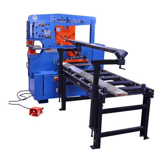
You have downloaded a manual for our
Model 9012-24M Ironworker.
This manual does not include all of the
optional tooling for this machine.
If you would like a tooling manual,
please download our #40 Tooling Manual.
START
STOP
START
PUNCH
SHEAR
RUN
JOG
PROBE
004085
JOG
LUBRICATE
BEFORE
OPERATING
19103
0481
9012-24M
MACHINE CAPACITIES
SPEC. BASED ON MILD STEEL-65,000 PSI TENSILE
PUNCH
PUNCH
THROAT DEPTH
STROKE
90 TONS
12" - 300MM
Ø1-1/16 THRU 1"
2.25" - 57MM
Ø27 THRU 25MM
FLAT SHEAR
ANGLE SHEAR
6"X6"X 1/2"
BLADE LENGTH 24" - 600MM
1X8 - 1/4X 24"
150X150X12MM
25X200 - 6X600MM
#019139
5,03
WHEN MITERING
DO NOT EXCEED
3 X 3 X 1/4
003195
0502
MODEL
H.P.
VOLT
SERIAL
HZ
FLA
SCOTCHMAN INDUSTRIES, INC.
PH
PSI
PHILIP, SOUTH DAKOTA, U.S.A.
BLADE LENGTH
PH. 605-859-2542
MADE IN U.S.A.
WARNING
TO PREVENT SERIOUS BODILY INJURY
NEVER-
Operate, install tooling, service or adjust machine without
proper instructions and without reading and understanding the
operator's manual and safety film.
NEVER-
Service machine with electrical power connected.
NEVER-
Operate any station without the respective strippers or
hold-downs in place.
NEVER-
Operate machine with protective guards removed.
NEVER-
Place any part of your body under blade, punch or moving
members.
NEVER-
Operate punch station without checking the punch to die
alignment and tightness.
(Check alignment and tightness daily.)
NEVER-
Punch half holes, punch or shear unknown materials, side load
press brakes.
SAFETY GLASSES REQUIRED WHEN
DO NOT REMOVE THIS SIGN FROM THIS MACHINE
OPERATING OR OBSERVING THIS MACHINE
003100
FOR MORE INFORMATION CONTACT SCOTCHMAN INDUSTRIES INC.
AT
1-800-843-8844
REV. 0310
LUBRICATE
BEFORE
OPERATING
19103
0481
DANGER
3120
0389
Advertisement
Table of Contents

Related Manuals for Scotchman 9012-24M


Summary of Contents for Scotchman 9012-24M
- Page 1 Punch half holes, punch or shear unknown materials, side load press brakes. SAFETY GLASSES REQUIRED WHEN DO NOT REMOVE THIS SIGN FROM THIS MACHINE OPERATING OR OBSERVING THIS MACHINE 003100 FOR MORE INFORMATION CONTACT SCOTCHMAN INDUSTRIES INC. 1-800-843-8844 REV. 0310 LUBRICATE BEFORE OPERATING...
- Page 2 MODEL 9012-24M IRONWORKER PRINTED SEPTEMBER 2021 SCOTCHMAN INDS. - 180 E. HWY 14 - PO BOX 850 - PHILIP, SD 57567 PHONE: 1-800-843-8844...
-
Page 3: Table Of Contents
TABLE OF CONTENTS SECTION DESCRIPTION PAGE # INTRODUCTION SAFETY PRECAUTIONS WARRANTY WARNING LABELS INSTALLATION & SET-UP 10-19 Physical Dimensions Machine Moving Procedures Physical Inspections Electrical Requirements Machine Start Up Machine Stroke Inspection & Adjustment MAINTENANCE 20-23 Lubrication Routine Lubrication Scheduled Maintenance MACHINE OPERATION 24-34 Punch Operation... - Page 4 TABLE OF CONTENTS SECTION DESCRIPTION PAGE # 6 x 6 Ninety Degree Notcher Rectangle Notcher Brakes Angle Iron Brake Channel Shear Pipe Notcher Picket Tool 7.10 Square Tube Shear 7.11 Optional Punch and Die Holders 7.11A 2-1/2" & 3" Die Inserts 7.11B Offset Die Holder 7.11C...
- Page 5 TABLE OF CONTENTS SECTION DESCRIPTION PAGE # IRONWORKER PARTS LISTS 72-93 Shear Arm Assembly Punch Assembly Stripper Assembly Urethane Stripper Upper Arm Assembly Stroke Control Assembly Hold Down Assembly Cylinder Assembly Connecting Link Assembly 9.10 Power Unit - Serial # 20661 & Up 9.11 Electrical Unit 9.12...
-
Page 6: Introduction
The ability of the operator to control the machine’s direction of movement at any point in the stroke (stop, jog or reverse) gives the Scotchman 9012-24M Ironworker a tremendous advantage over mechanical ironworkers. There is no chance of the Scotchman being "accidentally tripped". -
Page 7: Safety Precautions
2.0 SAFETY PRECAUTIONS The operators of this machine must be qualified and well trained in the operation of the machine. The operators must be aware of the capacities of the machine and the proper use of the hold down devices, strippers and guards provided with the machine. All of the guards, adjustable restrictors and awareness barriers must be installed on the machine and kept in good working order. -
Page 8: Warranty
2.1 WARRANTY Scotchman Industries Inc. will, within three years of date of purchase, replace F.O.B. the factory or refund the purchase price for any goods which are defective in materials or workmanship, provided that the buyer returns the warranty registration card within thirty days of the purchase date and, at the seller’s option, returns the defective goods freight and delivery prepaid to the seller, which shall be the... -
Page 9: Warning Labels
DANGER VOLTAGE LABEL 003140 FINGER BEYOND TOOL SHEAR 019107 U.S. FLAG DECAL 003195 3 X 3 X 1/4 MAX STICKER 010117 27" SCOTCHMAN DECAL 019139 90T CAPACITY DECAL 019103 LUBRICATE DECAL (4) 019105 GREASE POINT DECAL (7) 003175 CAUTION CONTAMINATION (Not shown.) - Page 10 FIGURE 1 Page 9...
-
Page 11: Installation & Set-Up
4.0 INSTALLATION & SET UP CAUTION: THIS SECTION DISCUSSES INSTALLATION AND SET-UP PROCEDURES. PLEASE READ THOROUGHLY BEFORE OPERATING THIS MACHINE. 4.1 PHYSICAL DIMENSIONS INCHES Floor to Punch Ram 43-3/16 109.7 Floor to Top of Die Holder 104.1 Floor to Punch Bolster 36-3/8 92.4 Floor to Bottom Rail... - Page 12 FIGURE 2 Page 11...
-
Page 13: Machine Moving Procedures
4.2 MACHINE MOVING PROCEDURES This machine is designed to be moved with a forklift. The weight of this machine is 4,000 pounds (1,818 Kg.). Check the capacity of the lifting equipment before attempting to move the machine. THIS MACHINE IS TOP HEAVY AND SHOULD BE MOVED WITH CARE AND ON FLAT SURFACES ONLY. -
Page 14: Physical Inspections
4.3 PHYSICAL INSPECTIONS After the machine has been located, remove the side shrouds and inspect the interior of the machine for possible shipping damages. CHECK SPECIFICALLY THE FOLLOWING ITEMS: Stroke control handles and limit switches. Pump and motor assembly. Hydraulic hoses and fittings. Starter box and control box. -
Page 15: Electrical Requirements
4.4 ELECTRICAL REQUIREMENTS CAUTION: TO PREVENT DAMAGE TO THE MOTOR AND DANGER TO THE OPERATOR, ALL ELECTRICAL CONNECTIONS SHOULD BE MADE BY A LICENSED ELECTRICIAN. All machines are wired for three phase electrical power unless otherwise specified. To insure satisfactory machine performance, the supply voltage should be (+ or -) 10% of the motor voltage rating. - Page 16 FIGURE 4A Page 15...
- Page 17 FIGURE 4B Page 16...
- Page 18 FIGURE 4C Page 17...
-
Page 19: Machine Stroke Inspection & Adjustment
4.6 MACHINE STROKE INSPECTION & ADJUSTMENT The stroke setting is important for the proper operation of the machine. If this setting has changed, the machine may over-travel and cause the cylinder to "bottom out". This continued condition will eventually cause the starter overload to open. It can also cause the hydraulic oil to overheat and damage hydraulic system components. - Page 20 START STOP START PUNCH SHEAR PROBE 004085 START STOP 201110 M6x12 START PUNCH SHEAR PROBE 004085 WHEN MITERING DO NOT EXCEED 3 X 3 X 1/4 003195 0502 7711 Sales - 7710 Assy. 9-1/32 (229mm) 6-25/32 (172mm) DOWN FIGURE 5 Page 19...
-
Page 21: Maintenance
5.1 LUBRICATION IMPORTANT: Before operating the 9012-24M, apply oil to the angle shear blades, bar shear blades and the punch and die. Re-oil punches and dies every 5 to 10 holes and blades every 10 to 15 cuts. The oil will allow the machine to shear, punch and strip more easily and increase tool life considerably. - Page 22 FIGURE 6 Page 21...
-
Page 23: Scheduled Maintenance
If the clearance between the pin and the bushing exceeds twelve (.012) thousandths of an inch (.3mm), replace the bushing. Since the 9012-24M can be used for a wide variety of applications with many optional tools, it may be necessary to include additional items in a scheduled maintenance program. - Page 24 FIGURE 7 Page 23...
-
Page 25: Machine Operation
6.0 MACHINE OPERATION 6.1 PUNCH OPERATION WHEN USING A URETHANE STRIPPER, SEE SECTION 7.13 FOR INSTRUCTIONS. ALWAYS WEAR SAFETY GLASSES. THE FIRST AND MOST IMPORTANT PROCEDURE IS THE PROPER METHOD OF CHANGING AND ALIGNING PUNCHES AND DIES. FIGURE 8 Page 24... - Page 26 ALIGNMENT AND REMOVAL OF PUNCHES AND DIES: WARNING: Failure to properly align punches and dies can cause serious bodily injury to personnel and/or damage to equipment. Please read carefully and understand the following method. It will also be helpful to refer to the safety dvd provided for a visual reference. If you did not receive a safety CD, please contact your dealer or the factory.
- Page 27 DO NOT PUNCH ANYTHING THICKER THAN THE PUNCH DIAMETER. This "rule of thumb" can be extended, but the punch supplier or Scotchman should be consulted first. (i.e. Do not punch plate thicker than 1/2 inch with a 1/2 inch diameter punch). This rule of thumb applies to mild steel and must be reduced when punching alloy steels.
- Page 28 Any edge distance less than this will result in a deformed workpiece. STAY WITHIN RATED PUNCHING CAPACITIES. Your 9012-24M Ironworker is designed to operate in mild steel. Within conservative limits, it can also operate in medium, carbon annealed steel and some forms of abrasion resistant steels.
-
Page 29: B Stripper Adjustment
6.1B STRIPPER ADJUSTMENT CAUTION: TO PREVENT PUNCH BREAKAGE ON THE RETURN STROKE, THE STRIPPER MUST BE ADJUSTED SO THAT THE BOTTOM OF THE STRIPPER IS PARALLEL WITH THE MATERIAL BEING PUNCHED. REFER TO FIGURE 10 BELOW. TO ADJUST THE STRIPPER: The height of the stripper is adjusted using the adjustment bolts (A &... -
Page 30: Bar Shear Operation
When using the Bar Shear on your Scotchman Ironworker, ALWAYS use the hold-down device. NEVER put any part of your body between the hold-down and the material to be sheared. -
Page 31: A Shear Arm Adjustment
THE BASIC METHOD OF OPERATING THE BAR SHEAR CONSISTS OF SIX STEPS: Place the selector switch in the START position and power the machine. Place the selector switch in the SHEAR position. Place the material to be sheared between the shear blades. Crank the hold-down device down to the material being sheared. - Page 32 Loosen the six adjusting screws (H) in the frame for the rub block (I) and remove the rub block by taking out the three mounting screws (G). (If excessive concave wear is noted on the rub block, it can be turned and the back surface used.) Set the pressure plate adjustment before resetting the rub blocks.
-
Page 33: B Shear Blade Adjustment
6.2B SHEAR BLADE ADJUSTMENT PROCEDURE (SERIAL #'S 21601M & UP) SEE FIGURE 12 ON THE FOLLOWING PAGE. Place the selector switch in the SHEAR position and allow the arms to raise completely. Crank the hold-down devise all the way up and remove the shear table. To remove the shear table, loosen the jam nut (F) on the bolts (C) and remove the bolt. - Page 34 2° CANT MATERIAL THICKNESS BLADE CLEARANCE QUICK GUIDE TO .035 (.030-.040) CHANGING BAR SHEAR BLADES .026 (.020-.030) .022 (.018-.026) 1st - remove lower blade .017 (.012-.022) 2nd - change upper blade .013 (.010-.017) 3rd - start bolts (E) in lower blade .009 (.007-.012) 4th - place shim between blades .004 (.004-.008)
- Page 35 THIS PAGE LEFT BLANK INTENTIONALLY. Page 34...
-
Page 36: Optional Tool Operation
There is a graphical illustration of the available tonnage at locations along the Upper Arm. SEE FIGURE 13 BELOW. This graph will be helpful in setting up various Scotchman or custom tooling. 7.1 6 X 6 ANGLE SHEAR The 6 x 6 angle shear is a component tool designed to shear angle iron. - Page 37 7.1A 6 X 6 ANGLE SHEAR INSTALLATION SEE FIGURE 14 ON THE FOLLOWING PAGE. The 6 x 6 Angle shear mounts in the tool station under the upper arm. Before mounting the tool under the arm, remove the upper blade and install the return springs (A).
- Page 38 CAUTION: IF THE ANGLE SHEAR SHOULD JAM FOR ANY REASON, DO NOT ATTEMPT TO FREE IT BY HAND!!! USE A PRY BAR OR SIMILAR DEVICE. REPLACE THE BLADES OR INSTALL SHIMS, DEPENDING ON WHAT CAUSED THE JAM. FIGURE 14 Page 37...
-
Page 39: Rod Shear
7.2 ROD SHEAR The rod shear is a component tool designed to shear sections of solid round and square stock. It has 9 round cavities that range from 1/4 to 1-1/4 inches (6 to 30mm) and one square cavity that has the capacity 1/4 to 1 inch (6 to 25mm). - Page 40 FIGURE 15 Page 39...
-
Page 41: X 6 Ninety Degree Notcher
7.3 6 X 6 NINETY DEGREE NOTCHER The 6 x 6 ninety degree notcher is a component tool designed to cut 90 degree Vee notches in angle and flat stock. It has a maximum capacity of 5/16 inch (8mm) thick mild steel. 7.3A 6 X 6 NINETY DEGREE NOTCHER INSTALLATION SEE FIGURE 16 ON THE FOLLOWING PAGE. - Page 42 FIGURE 16 Page 41...
-
Page 43: Rectangle Notcher
7.3C BLADE REPLACEMENT The lower blades are symmetrical and can be rotated to expose four cutting edges. The upper blade has two cutting edges. TO ROTATE OR REPLACE THE BLADES, use the following steps: CAUTION: THE UPPER CASTING OF THE NOTCHER IS HEAVY ENOUGH TO CAUSE INJURY IF DROPPED. - Page 44 7.4B RECTANGLE NOTCHER OPERATION CAUTION: BEFORE OPERATING THIS TOOL, THE DOWNSTROKE OF THE MACHINE MUST BE SET SO THAT THE FRONT OF THE TOP BLADE JUST PASSES THE LOWER BLADES, (FAR ENOUGH SO THAT THE WIDE PART OF THE UPPER BLADE JUST PASSES THE LOWER BLADES).
-
Page 45: Brakes
7.5 12 AND 24 INCH BRAKES Brakes are component tools designed to bend and form mild steel. They are shipped standard with dies to accommodate material up to 1/4 of an inch (6mm) thickness. The selector switch must be in the SHEAR position to operate these tools. - Page 46 If the parts require a bend of less than 90 degrees, adjust the down stroke of the machine until the desired bend is obtained. A great variety of standard brake dies can be used with this unit. These are available from Scotchman Industries or brake die suppliers. ALWAYS REMOVE THE TOOL WHEN IT IS NOT IN USE.
-
Page 47: Angle Iron Brake
7.6 ANGLE IRON BRAKE This brake is designed to form box frames out of angle iron. It has a maximum capacity of 1/4" (6mm). 7.6A ANGLE IRON BRAKE INSTALLATION SEE FIGURE 20 ON THE FOLLOWING PAGE. This brake mounts in the punch station and the selector switch must be in the PUNCH position to operate this tool. - Page 48 FIGURE 20 Page 47...
-
Page 49: Channel Shear
7.7 CHANNEL SHEAR The Channel Shear is a component tool designed to shear 2 to 6 inch (51 to 152mm) standard channel on this model. 7.7A CHANNEL SHEAR INSTALLATION SEE FIGURE 21 ON THE FOLLOWING PAGE. The Channel Shear installs under the upper arm in the tool station. The selector switch must be in the SHEAR position to operate this tool. - Page 50 — PROCEDURE FOR SHEARING: Lubricate the blades before making the first cut and every 10 to 15 cuts, thereafter. This lubrication is critical on the channel shear. Position the workpiece. Snug the movable blades up to the channel’s flange. Depress the foot switch and shear the workpiece.
-
Page 51: Pipe Notcher
7.8 PIPE NOTCHER The Pipe Notcher is a component tool designed to saddle cut pipe or tubing for applications such as railings. There are notchers available to notch angles in pipe and tubing, also. For prices and availability, contact your local dealer or the factory. 7.8A PIPE NOTCHER INSTALLATION SEE FIGURE 22 ON THE FOLLOWING PAGE. - Page 52 FIGURE 22 7.8C PIPE NOTCHER CAPACITIES Two inch (2") Schedule 80 is the maximum thickness that can be cut. Lighter weight tubing may be cut, but will probably require different dies for best cutting results. Separate dies are required for each size of pipe or tubing being notched.
-
Page 53: Picket Tool
7.9 PICKET TOOL INSTALLATION & OPERATION This tool mounts in the punch station only. REFER TO THE DRAWING ON THE FOLLOWING PAGE. The machine must be in the PUNCH position to operate this tool. Remove the die holder, stripper and the punch retaining nut. Install the tool so that the punch ram aligns with the ram on the picket tool and anchor it to the punch bolster with the finger clamps (C) provided. - Page 54 FIGURE 24 Page 53...
-
Page 55: Square Tube Shear
7.10 SQUARE TUBE SHEAR SEE FIGURE 25 ON THE FOLLOWING PAGE. The square tube shear is designed to shear square tubing from 1/4" to 2" (6mm to 51mm). 16 gauge (.060 or 1.5mm) is the maximum material thickness. 7.10A SQUARE TUBE SHEAR INSTALLATION SEE FIGURE 25 ON THE FOLLOWING PAGE. - Page 56 FIGURE 25 Page 55...
-
Page 57: Optional Punch And Die Holders
7.11 OPTIONAL PUNCH AND DIE HOLDERS 7.11A 2-1/2" AND 3" DIE INSERTS The 2-1/2 and 3 inch (63 and 76mm) die inserts are designed to fit in the standard die holder in place of the 2 inch (51mm) insert. They are used in oversize punching applications. for applications, REFER TO THE PUNCH AND DIE SECTION OF THE TOOLING PARTS MANUAL. -
Page 58: E Heavy Duty Split Ring Retaining Nut
7.11E HEAVY DUTY SPLIT RING RETAINING NUT SEE FIGURE 26 BELOW. The heavy duty split-ring retaining nut is used in oversize punching applications that require a punch with a 2 inch (51mm) shank diameter (E). This retaining nut requires a pin wrench (F), which should be ordered when ordering the nut. -
Page 59: Optional Gauging Equipment
7.12 OPTIONAL GAUGING EQUIPMENT AND CONTROLS 7.12A 48 INCH DELUXE BACK GAUGE The 48 inch back gauge mounts on the drop-off side of the machine and will reach all three stations from one point. It is designed to be used as a length stop in the shear, punch and tooling stations. It is available with a scale, a digital readout or an electrically controlled stop. -
Page 60: Urethane Stripper
7.13 URETHANE STRIPPER Scotchman does not recommend this unit for all general punching applications. However, using this specially designed "Non Deform" stripper unit does offer a significant advantage over a standard stripper arrangement in reducing distortion when punching a confined pattern or series of holes in flat bar or plate. - Page 61 7.13A CHANGING THE URETHANE SPRINGS If the unit is constantly over stroked or over a period of time, it may be necessary to renew the urethane springs. REFER TO FIGURE 27 ON PAGE 61. The springs should be checked periodically. (A sure sign of over stroking is cracking or splitting of the springs.) ...
- Page 62 FIGURE 27 Page 61...
- Page 63 7.13B INSTALLING THE URETHANE STRIPPER & PUNCH & DIE REFER TO FIGURE 28. Raise the top limit switch to its highest position. Power the machine and let the punch ram retract to its full UP position. Open the standard stripper and remove it from the machine by removing the left hand mounting bolt.
- Page 64 Slide the bottom half of the urethane stripper onto the stripper mounting plate (A) from the inside of the machine. Make sure that the spring retainers (G) are positioned so that the lip on the retainer fits against the machined area on the front of the mounting plate (A). Finger tighten the retaining nuts (I). Power the machine and jog the ram down until the urethane stripper contacts the top of the die die holder.
-
Page 65: Weld Coupon Bender Tool
After bending the weld test coupon, let the tool return to the resting position. Remove the test coupon and inspect the weld. The tool can be seen in use at www.scotchman.com. CAUTION: REMOVE THE WELD COUPON BENDER WHEN IT IS NOT IN USE. - Page 66 FIGURE 29 Page 65...
-
Page 67: Multi-Shear Tool
7.15 MULTI-SHEAR TOOL The Multi-Shear tool is designed to shear standard Unistrut profiles, as well as many other specialty profiles. 7.15A MULTI-SHEAR TOOL INSTALLATION SEE FIGURE 30 ON THE FOLLOWING PAGE. If the punch and die are mounted on the machine, REMOVE THEM. Turn the machine on and put it in the SHEAR position. - Page 68 FIGURE 30 Page 67...
-
Page 69: Trouble Shooting Guide
8.0 TROUBLE SHOOTING GUIDE 8.1 ELECTRICAL TROUBLE SHOOTING-MOTOR CAUTION: ALL ELECTRICAL WORK PERFORMED ON THE 9012 IRONWORKER SHALL BE DONE BY A QUALIFIED ELECTRICIAN. MOTOR WILL NOT RUN: Check to be sure that the disconnect switch is in the ON position and that the selector switch is in the START position. -
Page 70: Limit Switch Inspection
TO TEST THE FOOT SWITCH, place the selector switch in the START position and power the machine. Place the selector switch in the PUNCH or the SHEAR position and test the voltage between terminal #’s 4, 5, 10 & ground. Test between terminal # 4 & ground to determine that there is voltage present at the foot switch. -
Page 71: Hydraulics
8.4 HYDRAULICS THE MOST COMMON HYDRAULIC PROBLEMS ARE: Low level of hydraulic oil in the reservoir: The reservoir holds 13.5 U.S. gallons (51 liters). The level should be 2 inches (50mm) below the top of the reservoir. Contamination in the hydraulic oil: The oil and the filter should be changed at least once a year and any time that there is a possibility that contamination has gained access into the system. - Page 72 Oil all of the seals before reassembling the cylinder. After the piston and head are assembled on the shaft, they can be tapped back into the tube with a brass or plastic hammer. Re-thread the cylinder head into the tube. Reconnect the hoses to the cylinder.
-
Page 73: Ironworker Parts Lists
9.0 9012 IRONWORKER PARTS LISTS FOR YOUR CONVENIENCE, ALWAYS GIVE YOUR COMPLETE SERIAL NUMBER WHEN ORDERING PARTS. 9.1 SHEAR ARM ASSEMBLY (SER. # 21601M & UP) ITEM PART # DESCRIPTION 030650 Rub Block 030550 Shear Arm (Includes C & G) 080169 Brass Bushings 080031... - Page 74 FIGURE 32 Page 73...
-
Page 75: Punch Assembly
9.2 PUNCH ASSEMBLY ITEM PART # DESCRIPTION 030640 Punch Bolster (Ser.# 21600 & Prior) 080424 Punch Bolster (Ser.# 21601M & Up) 221420 M-16 SHCS 113017 Reid Washer 201625 M-16 HHCS 006013 Die Holder 218058 M-10 Set Screw 006202 #82 Die Insert (2 Inch) 204220 M-10 x 30 HHCS 026713... - Page 76 P/N 010236 Kit Includes M, W, EE, FF and GG. 221120 M8 x 25 221120 M8 x 25 221120 M8 x 25 221120 M8 x 25 221120 M8 x 25 221120 M8 x 25 221120 M8 x 25 221120 M8 x 25 221315 M12x40 221315...
-
Page 77: Stripper Assembly
9.3 STRIPPER ASSEMBLY ITEM PART # DESCRIPTION 007228 Stripper (Includes H, I, J, N & O) 007229 Adjustment Screw (Left) 007237 Stripper Stud (Left) 007240 Spring Retainer 007241 Spring 007236 Adjustment Screw (Right) 007239 Spring Rod 220014 M-6 x 10 BHCS 007268 Sight Glass (5 x 2-5/16) 001541... - Page 78 FIGURE 34 Page 77...
-
Page 79: Urethane Stripper
9.4 URETHANE STRIPPER ITEM PART # DESCRIPTION 025443 Post Retainer 025450 Lexan Shield 025455 Urethane Spring 025454 Spring Post 025456 Spring Spacer 025453 Post Nut 025441 Top Plate 073691 Knob 221326 M-12 x 65 SHCS 218023 M-6 x 12 SS 025447 Stripper Plate 026039... - Page 80 FIGURE 35 Page 79...
-
Page 81: Upper Arm Assembly
9.5 UPPER ARM ASSEMBLY ITEM PART # DESCRIPTION 030560 Upper Arm (Includes A, B, D & F) 006172 Bushing 080174 Grease Bolt 012070 Upper Arm Bushing 035666 Upper Arm Pin 032074 Punch Pin & Bushing 212016 M-16 Lock Washer Page 80... - Page 82 FIGURE 36 Page 81...
-
Page 83: Stroke Control Assembly
9.6 UPPER PANEL & STROKE CONTROL ITEM PART # DESCRIPTION 007711 Control Cover - Painted 077907 Edge Material 073206 M-6 Hex Nut 562040 Wire Cable Clamp 220020 M-6 x 16 BHCS 011862 E-Stop Operator 011500 Stop Legend 011872 Mounting Adaptor 011867 Contact Block 011869... - Page 84 FIGURE 37 Page 83...
-
Page 85: Hold Down Assembly
9.7 HOLD DOWN ASSEMBLY ITEM PART # DESCRIPTION 013185 Guard 080342 Housing 080337 Post-Left 080336 Post-Right 017340 Key 7 x 7 x 24 080347 Gear-Left 003105 Warning Label 080348 Gear-Center 080349 Gear-Right 080338 Wheel Shaft 080344 Base 201110 M-6 x 12 HHCS 141415 1/4 x 1-3/4 Roll Pin 017342... - Page 86 FIGURE 38 Page 85...
-
Page 87: Cylinder Assembly
9.8 CYLINDER ITEM PART # DESCRIPTION 006190 Clevis Pin 030580 Cylinder Clevis 030605 Cylinder (Includes B) 030595 Cylinder Anchor Pin 016620 2" Snap Ring 030233 Cylinder Shroud 224205 M-10 WLCS 030631 Rear Shroud - Ser. # 20600M & Prior 080423 Rear Shroud - Ser. -
Page 88: Connecting Link Assembly
9.9 CONNECTING LINK ASSEMBLY ITEM PART# DESCRIPTION 030570 Connecting Link 006190 Connecting Link Pins 016620 2" Snap Ring 243101 M-6 Grease Zerk FIGURE 40 Page 87... -
Page 89: Power Unit - Serial # 20661 & Up
9.10 POWER UNIT ITEM PART # DESCRIPTION 006875 Filter Housing 006860 Filter (Ser.#’s 21772M0613 & Prior) 006863 Filter (Ser.#’s 21773M0613 & Up) Fitting 006840 Return Hose 016088 Breather Cap 017105 1" Nipple 003810 Ball Valve Fitting 006830 Suction Hose Fitting Motor (Must specify.) 007340 Pump... - Page 90 FIGURE 41 Page 89...
-
Page 91: Electrical Unit
9.11 ELECTRICAL UNIT ITEM PART # DESCRIPTION DIL-M 011930 Transformer (Without Work Light) 011861 Transformer (With Work Light) 011933 Primary Fuse 011835 Secondary Fuse 011846 Coil 562453 Foot Switch 011753 Cord (Foot Switch) 562452 Micro Switch (Foot Switch) 011854 Disconnect Switch 011895 Disconnect Switch Knob See note. - Page 92 FIGURE 42 Page 91...
- Page 93 FIGURE 43 Page 92...
-
Page 94: Standard Die Holder W/Inserts
9.12 STANDARD DIE HOLDER WITH INSERTS ITEM PART # DESCRIPTION 006013 Cast Die Holder 006302 3" Die Insert (76mm) 006252 2-1/2" Die Insert (63mm) 006202 2" Die Insert (50mm) 218058 M-10 Set Screw 201625 M-16 HHCS 113017 Reid Washer 077145 219060 M-10 x 50 SS 204220... -
Page 95: Punch Retaining Nuts
9.13 PUNCH RETAINING NUTS ITEM PART# DESCRIPTION 026501 Ring Nut 026502 Split-Ring 026503 Retaining Ring 221212 M-10 SHCS 026504 M-8 Brass Set Screw 016095 #40 Punch Retaining Nut 016096 #45 Punch Retaining Nut 018507 Wrench For A 019098 Wrench For F & G 026500 Complete Heavy Duty Nut Includes A, B, C, D &... - Page 96 THIS PAGE LEFT BLANK INTENTIONALLY. Page 95...
-
Page 97: Supplement For Older Models
10.0 SUPPLEMENT FOR OLDER MODELS 10.1 SHEAR ARM ASSEMBLY (SERIAL #'S 21600M & PRIOR) ITEM PART # DESCRIPTION 030650 Rub Block 030550 Shear Arm 080169 Brass Bushings 080031 24" Shear Blades 006250 Lower Blade Holder 007100 Shear Table 010182 Main Pin Bushing 030555 Shear Arm Pin 080174... - Page 98 FIGURE 46 Page 97...
- Page 99 10.2 SHEAR BLADE ADJUSTMENT PROCEDURE (SERIAL #'S 21600 & PRIOR) SEE FIGURE 47 ON THE FOLLOWING PAGE. Remove the shear table (K) and unlock the lock nuts on the back-up screws (E). Loosen the four (4) socket head retaining screws (D) that hold the lower blade support (C) to the top of the shear bed and remove the blade and the lower blade holder.
- Page 100 FIGURE 47 Page 99...
Need help?
Do you have a question about the 9012-24M and is the answer not in the manual?
Questions and answers