Table of Contents
Advertisement
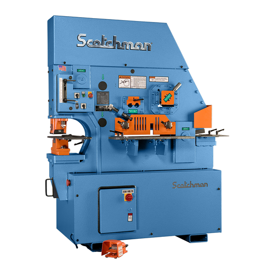
You have downloaded a manual for our
Model FI-8510-20M Ironworker.
This manual does not include all of the
optional tooling for this machine.
If you would like a tooling manual,
please download our #40 Tooling Manual.
15377
START
STOP
START
PUNCH
SHEAR
RUN
JOG
PROBE
JOG
TO PREVENT SERIOUS BODILY INJURY
WARNING
NEVER-
Operate, install tooling, service or adjust machine without
proper instructions and without reading and understanding the
operator's manual and safety film.
NEVER-
Service machine with electrical power connected.
NEVER-
Operate any station without the respective strippers or
hold-downs in place.
NEVER-
Operate machine with protective guards removed.
NEVER-
Place any part of your body under blade, punch or moving
members.
NEVER-
Operate punch station without checking the punch to die
alignment and tightness.
(Check alignment and tightness daily.)
NEVER-
Punch half holes, punch or shear unknown materials, side load
press brakes.
SAFETY GLASSES REQUIRED WHEN
DO NOT REMOVE THIS SIGN FROM THIS MACHINE
OPERATING OR OBSERVING THIS MACHINE
003100
FOR MORE INFORMATION CONTACT SCOTCHMAN INDUSTRIES INC.
AT
1-800-843-8844
REV. 0310
FULLY INTEGRATED
8510-20M
MACHINE CAPACITIES
SPEC. BASED ON MILD STEEL-65,000 PSI TENSILE
PUNCH
FLAT SHEAR
85 TONS
BLADE LENGTH 20" - 508MM
Ø1-1/16 THRU 1"
1X12 - 3/4X 20"
Ø27 THRU 25MM
25X300 - 19X508MM
THROAT DEPTH
RECT. NOTCHER
10" - 254MM
3"w X 5"d X 1/2"t
4758
PUNCH STROKE
76X127X12MM
3.45" - 87MM
ROD SHEAR
ANGLE SHEAR
Ø1-1/2" ROUND
Ø38MM
6"X6"X 1/2"
150X150X12MM
1-1/4 SQUARE
32 SQUARE
#015380
1,05
4295
GUARD FACE TO SHEAR EDGE
15600 Assy.
15788
ADD 4-1/4" (108MM)
MODEL
H.P.
VOLT
SERIAL
HZ
FLA
SCOTCHMAN INDUSTRIES, INC.
PH
PSI
PHILIP, SOUTH DAKOTA, U.S.A.
BLADE LENGTH
PH. 605-859-2542
MADE IN U.S.A.
113017
201610
230 Volts
19121
OFF
11856
EATON
DANGER
ELECTRICAL HAZARD
Turn off power
and lock out
before servicing.
3122
1213
11893Raw 11898 Assy.
WARNING
TO PREVENT SERIOUS BODILY
INJURY DO NOT PLACE FINGERS
BEYOND THESE GUARDS
1210
003105
10mm ss
12mm
6 mm ss
10mm ss
10mm ss
10mm
12mm
10mm ss
12mm
10mm
12mm
25070
10mm ss
10mm
10mm
12mm
15273
10mm ss
10mm ss
10mm ss
113017
201610
25078
Advertisement
Table of Contents

Related Manuals for Scotchman FI-8510-20M


Summary of Contents for Scotchman FI-8510-20M
- Page 1 Punch half holes, punch or shear unknown materials, side load press brakes. SAFETY GLASSES REQUIRED WHEN DO NOT REMOVE THIS SIGN FROM THIS MACHINE OPERATING OR OBSERVING THIS MACHINE 003100 FOR MORE INFORMATION CONTACT SCOTCHMAN INDUSTRIES INC. 1-800-843-8844 REV. 0310 10mm ss 12mm 6 mm ss...
- Page 2 MODEL FI-8510-20M IRONWORKER SEPTEMBER 2021 SCOTCHMAN INDS. - 180 E US HWY 14 - PO BOX 850 - PHILIP, SD 57567 Call: 1-605-859-2542...
-
Page 3: Table Of Contents
TABLE OF CONTENTS SECTION DESCRIPTION PAGE # INTRODUCTION SAFETY PRECAUTIONS WARRANTY WARNING LABELS INSTALLATION AND SET-UP 10-17 Physical Dimensions Machine Moving Procedures Physical Inspection Electrical Requirements Machine Start-Up Machine Stroke Inspection and Adjustment MAINTENANCE 20-23 Lubrication Scheduled Maintenance MACHINE OPERATION 24-42 Punch Operation Bar Shear Operation... - Page 4 TABLE OF CONTENTS SECTION DESCRIPTION PAGE # Rectangle Notcher Operation 6.6A Rectangle Notcher Blade Adjustment or Replacement Jog Control OPTIONAL TOOLS 42-67 Pipe Notcher 6 x 6 Ninety Degree Notcher 12 & 24 Inch Brakes Angle Iron Brake Channel Shear Picket Fence Tool Square Tube Shear Optional Die Holders and Punch Retaining Nuts...
- Page 5 TABLE OF CONTENTS SECTION DESCRIPTION PAGE # PARTS LISTS 72-95 Tooling Arm Assembly Drive Arm Assembly Flat Bar Shear Assembly 6" Angle Shear Assembly Rod Shear Assembly Notcher Assembly Upper Panel Stripper Assembly Sheet Metal & Cylinder 9.10 Power Unit 9.11 Punch Retaining Nuts 9.12...
-
Page 6: Introduction
On this model, the tools are an integral part of the machine and are designed for the user that wants the advantage of five separate working stations without the necessity of tooling changes. While this is a fully-integrated machine, Scotchman still offers many optional tools that are adaptable to this model. -
Page 7: Safety Precautions
2.0 SAFETY PRECAUTIONS The operators of this machine must be qualified and well trained in the operation of the machine. The operators must be aware of the capacities of the machine and the proper use of the hold down devices, strippers and guards provided with the machine. All of the guards, adjustable restricters and awareness barriers must be installed on the machine and kept in good working order. -
Page 8: Warranty
2.1 WARRANTY Scotchman Industries, Inc. will, within three (3) years of the date of purchase, replace F.O.B. the factory or refund the purchase price for any goods which are defective in materials or workmanship, provided the buyer returns the warranty registration card within thirty (30) days of the purchase date and, at the seller’s option, returns the defective goods freight and delivery prepaid to the seller, which shall be the... -
Page 9: Warning Labels
3.0 WARNING LABELS ITEM PART # DESCRIPTION 003110 PUNCH WARNING 003100 MAIN WARNING LABEL 003105 FINGERS BEYOND (SHEAR) 003120 DANGER: VOLTAGE 003140 FINGERS BEYOND (TOOL) 004349 NOTCHER NOTICE 015380 CAPACITY LABEL PAGE 8... - Page 10 FIGURE 1 PAGE 9...
-
Page 11: Installation And Set-Up
4.0 INSTALLATION AND SET-UP CAUTION: THIS SECTION DISCUSSES INSTALLATION AND SET-UP PROCEDURES. PLEASE READ THOROUGHLY BEFORE OPERATING THIS MACHINE. 4.1 PHYSICAL DIMENSIONS ITEM DESCRIPTION INCHES Floor to Punch Ram 109.2 Floor to Top of Die 37-1/4 94.6 Floor to Top of Bolster 31-1/4 79.4 Floor to Bottom of Bolster... - Page 12 FIGURE 2 PAGE 11...
-
Page 13: Machine Moving Procedures
4.2 MACHINE MOVING PROCEDURES CAUTION: BE SURE THAT ANY LIFTING DEVICE HAS ADEQUATE CAPACITY BEFORE ATTEMPTING TO MOVE THIS MACHINE. THIS MODEL WEIGHS 4,500 LB. (2,068 KG.). IT IS DESIGNED TO BE MOVED BY A FORKLIFT, ONLY. THERE ARE FORKLIFT SLOTS DESIGNED INTO THE BASE OF THE MACHINE FOR THIS PURPOSE. -
Page 14: Physical Inspection
4.3 PHYSICAL INSPECTIONS Any damage to the machine during shipment should be reported to the delivery carrier immediately. A damage report must be made so that a claim can be placed. The carrier is responsible for shipping damage, but it is the customer.s responsibility to immediately report damages, external or internal. After the machine has been located, remove the side shrouds and inspect the interior of the machine for possible shipping damages. -
Page 15: Electrical Requirements
4.4 ELECTRICAL REQUIREMENTS CAUTION: TO PREVENT DAMAGE TO THE MOTOR AND DANGER TO THE OPERATOR, ALL ELECTRICAL CONNECTIONS SHOULD BE MADE BY A LICENSED ELECTRICIAN. All machines are wired for three phase electrical power unless otherwise specified by customer. The supply voltage should be (+ or -) 10% of the motor voltage rating, to insure satisfactory machine performance. - Page 16 NORMAL POSITION OPTIONAL EQUIPMENT PAGE 15A COMPONENT DRAWN BY: SCALE: PART NAME: SCOTCHMAN IND. FI85 3PH ELEC. SCHEMATIC CR - CONTROL RELAY M - MOTOR START RELAY CVC - CONTROL VALVE COIL OL - OVERLOAD (THERMAL) DISC - DISCONNECT PB - PUSH BUTTON...
- Page 17 NORMAL POSITION OPTIONAL EQUIPMENT PAGE 15B COMPONENT DRAWN BY: SCALE: PART NAME: SCOTCHMAN IND. FI85 230V 1PH ELEC. SCHEMATIC CR - CONTROL RELAY M - MOTOR START RELAY CVC - CONTROL VALVE COIL OL - OVERLOAD (THERMAL) DISC - DISCONNECT...
- Page 18 1 PHASE 3 PHASE INCOMING POWER INCOMING POWER DISCONNECT DISCONNECT 13 NO 13 NO CONTACTOR CONTACTOR CONTACTOR CONTACTOR 14 NO 14 NO _OL_ _OL_ OVERLOAD OVERLOAD OVERLOAD OVERLOAD TEST TEST ZB32-32 ZB32-32 RESET RESET SET TO SET TO MOTOR MOTOR TO MOTOR TO MOTOR FIGURE 4C...
- Page 19 All New Machines Now Have The 250 KVA Transformer as Standard Equipment. WITH WORK LIGHT HIGH VOLTAGE C0NNECTION 250 KVA ( 440-480 VOLT 3PH ) PRIMARY SIDE FUSE FUSE H1-H2 H1-H3 H1-H4 H1-H5 EATON 250 VA CO250E6U XF-X2 XF-X4 XF-X3 FUSE SECONDARY SIDE WHITE...
- Page 20 OPTIONAL TOOLING IS AVAILABLE VISIT WWW.SCOTCHMAN.COM FOR MORE INFORMATION 026350 - SQUARE TUBE SHEAR 243101 243101 1302 203212 1309 203217 026350 - Assy. 1313 243101 203217 201210 201210 201210 201210 203217 26306 026500 - HEAVY DUTY RETAINING NUT (punch not included)
-
Page 21: Machine Start-Up
4.5 MACHINE START-UP BEFORE STARTING THIS MACHINE, TAKE TIME TO THOROUGHLY REVIEW THE VHS SAFETY TAPE OR SAFETY CD AND THE OPERATOR’S MANUAL. This machine is equipped with a lock-out, disconnect switch as standard equipment. We strongly urge you to follow the OSHA directive CFR-1910.147 (effective 09-01-90) regarding lock-out, tag-out procedures. BEFORE POWERING THE MACHINE be sure that all packing materials and tools have been removed from the machine and that all work stations are clear. - Page 22 Punch half holes, punch or shear unknown materials, side load SAFETY GLASSES REQUIRED WHEN press brakes. OPERATING OR OBSERVING THIS MACHINE DO NOT REMOVE THIS SIGN FROM THIS MACHINE 003100 FOR MORE INFORMATION CONTACT SCOTCHMAN INDUSTRIES INC. 1-800-843-8844 REV. 0310 10mm ss 12mm 6 mm ss...
-
Page 23: Maintenance
5.0 MAINTENANCE The Scotchman Ironworker is an exceptionally rugged machine designed for long life with a minimum amount of maintenance. A regular program of servicing will extend the life of the machine and prevent costly down time. 5.1 LUBRICATION IMPORTANT: Before operating the 6509-24M, apply oil to the angle shear blades, bar shear blades and the punch and die. - Page 24 FIGURE 6 PAGE 21...
-
Page 25: Scheduled Maintenance
The following is a list of some important items that should be included in a scheduled maintenance program. Since the FI-8510-20M can be used for a wide variety of applications with many optional tools, every user must design and implement a scheduled maintenance program that fits their needs. - Page 26 FIGURE 7 PAGE 23...
-
Page 27: Machine Operation
6.0 MACHINE OPERATION 6.1 PUNCH OPERATION THE FIRST AND MOST IMPORTANT PROCEDURE IS THE PROPER METHOD OF CHANGING AND ALIGNING PUNCHES AND DIES. ALWAYS WEAR SAFETY GLASSES. FIGURE 8 PAGE 24... - Page 28 ALIGNMENT AND REMOVAL OF PUNCHES AND DIES: WARNING: Failure to properly align punches and dies can cause serious bodily injury and/or damage to equipment. Please read carefully and understand the following method. It will also be helpful to refer to the safety tape provided for a visual reference. If you did not receive a safety tape, please contact your dealer or the factory.
- Page 29 B. KEYED PUNCHES: This machine is equipped with a 1/4 inch (6.3mm) keyed punch ram. When punching holes other than rounds, we recommend using keyed punches. All Scotchman shaped punches are supplied with the keyway as standard equipment. NOTE: If you do not use keyed punches, it may be helpful to hold the body of the punch with a wrench while tightening the punch retaining nut.
- Page 30 D. PROPER ADJUSTMENT OF THE STRIPPER. (SEE FIGURE 9 BELOW.) The height of the stripper is adjusted using the adjustment bolts (A & B). The stripper is opened by pushing up on item (C) and swinging it out toward the front of the machine.
- Page 31 DO NOT PUNCH ANYTHING THICKER THAN THE PUNCH DIAMETER. This "rule of thumb" can be extended, but the punch supplier or Scotchman should be consulted first, i.e. (Do not punch plate thicker than 1/2 inch with a 1/2 inch diameter punch.) This rule of thumb applies to mild steel only and must be reduced when punching alloy steels.
- Page 32 ► NOTE: When punching larger diameter holes or alloy steels, set the down stroke of the machine so that the punch stops just above the plane of the die, approximately fifteen thousandths of an inch (.3mm). This will reduce the punching shock encountered in these applications. Rated on mild steel having 65,000 psi tensile.
-
Page 33: Bar Shear Operation
HOLD-DOWN DEVICE TO ITS DOWN POSITION. When using the bar shear on your Scotchman Ironworker, always use the hold-down device. Never put any part of your body between the hold-down and the material to be sheared. A maximum clearance of 1/8"... - Page 34 Place the selector switch in the SHEAR position. Place the material to be sheared between the shear blades. Adjust the hold-down device down until it contacts the material to be sheared and tighten both hold-down knobs. REFER TO SECTION 6.2A. This prevents "kick-up" of the workpiece and possible damage to the machine.
-
Page 35: A Hold Down Adjustment
6.2A HOLD-DOWN ADJUSTMENT Ensure that the hold-down is correctly adjusted for the relevant material. NEVER allow the ends of the material to pass beyond the hold-down when shearing. This may cause serious damage to the machine. Always feed material from the hold-down side. Keep the blade area clean. -
Page 36: B Shear Blade Adjustment
6.2B SHEAR BLADE ADJUSTMENT To set the blades, lower the arm so that the upper blade crosses the lower blade. (If fitting new or re-ground blades, ensure that the lower blade is fully adjusted away from the upper blade before lowering the arm.) Switch off the machine. -
Page 37: Tooling Arm Adjustment
6.3 TOOLING ARM ADJUSTMENT For parts identification, SEE FIGURE 15 ON THE FOLLOWING PAGE. Adjustment of the tooling arm is maintained by a pressure plate at the pivot point, two rub plates backing up the arm and the two rub plates at the notcher station. CAUTION: BEFORE MAKING ANY ADJUSTMENTS ON THE TOOLING ARM, THE BAR SHEAR BLADES, ANGLE SHEAR BLADES AND ROD SHEAR BLADES MUST BE BACKED OFF TO PREVENT DAMAGE TO THE BLADES. - Page 38 FIGURE 15 PAGE 35...
-
Page 39: Angle Shear Operation
6.4 ANGLE SHEAR OPERATION The angle shear on this model is a crop-off design that parts the material without a slug. The maximum capacity of the angle shear is 6 x 6 x 1/2 inch (157 x 157 x 12mm) mild steel. To prevent kick-up of the material, adjust the hold-down device to within 1/16 of an inch (1.5mm) of the material. - Page 40 FIGURE 16 PAGE 37...
-
Page 41: Rod Shear Operation
6.5 ROD SHEAR OPERATION The rod shear cavity is designed to shear up to 1-1/2 inch (38mm) round and 1-1/4 inch (31mm) square rods. To prevent kick-up of the material, adjust the hold-down device to within 1/16 inch (1.5mm) of the material. - Page 42 FIGURE 17 PAGE 39...
-
Page 43: Rectangle Notcher Operation
6.6 RECTANGLE NOTCHER OPERATION This tool is operated with the selector switch in the PUNCH position. CAUTION: WHEN THE NOTCHER STATION IS NOT IN USE, BE SURE THAT THE GUARD IS IN THE FULL DOWN POSITION, TO PREVENT ANYONE FROM STORING TOOLS OR MATERIAL ON THE TABLE OR IN THE BLADE CAVITY. - Page 44 Install the notcher table (H) and adjust the guard down to the proper height. FIGURE 18 PAGE 41...
-
Page 45: Jog Control
POSITION THE SELECTOR SWITCH IS SET IN. 7.0 OPTIONAL TOOLS This segment will cover the optional tools that can be purchased for the FI-8510-20M, along with the proper and safe methods to install and operate them. As with all functions of this machine, safety glasses are required when using any of these tools. - Page 46 CAUTION: WITH THE PIPE NOTCHER MOUNTED IN THE MACHINE, THE DOWN STROKE OF THE MACHINE MUST BE ADJUSTED TO PREVENT DAMAGE TO THE TOOL AND POSSIBLE INJURY TO THE OPERATOR. THE UPPER DIE SHOULD NOT PASS THE LOWER DIE BY MORE THAN 1/32 OF AN INCH (.8MM). FIGURE 19 PAGE 43...
- Page 47 7.1B PIPE NOTCHER OPERATION The following is Scotchman Industries’ recommendation for maintenance and alignment of this tool. PLEASE READ CAREFULLY BEFORE USE. TO ACHIEVE THE BEST RESULTS FROM YOUR UNIT, PLEASE OBSERVE THESE SIMPLE RULES: Keep the unit clean. Whenever dirt or metal chips accumulate, remove the 8mm limit screw located in the center, at the rear of the punch.
- Page 48 FIGURE 20 PAGE 45...
-
Page 49: X 6 Ninety Degree Notcher
7.2 6 X 6 NINETY DEGREE NOTCHER The 6 x 6 ninety degree notcher is a component tool designed to cut 90 degree Vee notches in angle and flat stock. It has a maximum capacity of 5/16 inch (8mm) thick mild steel. 7.2A 6 X 6 NINETY DEGREE NOTCHER INSTALLATION SEE FIGURE 21 ON THE FOLLOWING PAGE. - Page 50 FIGURE 21 PAGE 47...
-
Page 51: 24 Inch Brakes
7.3 12 & 24 INCH BRAKES Brakes are component tools designed to bend and form mild steel. They are shipped standard with dies to accommodate material up to 1/4 of an inch (6.3mm) thickness. 7.3A 12 & 24 INCH BRAKE INSTALLATION SEE FIGURE 22 ON THE FOLLOWING PAGE. - Page 52 FIGURE 22 PAGE 49...
- Page 53 If parts require bends of less than 90 degrees, adjust the stroke until the desired bend is obtained. A great variety of standard brake dies can be used with this unit. Dies are available from Scotchman Industries or your local dealer. All brakes are shipped with 2 inch (50mm) vee opening dies, unless otherwise specified.
- Page 54 B R A K E T O N N A G E C H A R T PRESSURE IN TONS PER LINEAR FOOT REQUIRED TO MAKE 90 DEGREE AIR BEND IN MILD STEEL THICKNESS WIDTH OF V-DIE OPENING OF METAL GAUGE INCHES 1/4 5/16 3/8 1/2 5/8 3/4 7/8 1-1/8 1-1/4 1-1/2...
-
Page 55: Angle Iron Brake
7.4 ANGLE IRON BRAKE This brake is designed to form box frames out of angle iron. It has a maximum capacity of 1/4" (6mm). 7.4A ANGLE IRON BRAKE INSTALLATION SEE FIGURE 24 ON THE FOLLOWING PAGE. This brake mounts in the punch station and the selector switch must be in the PUNCH position to operate this tool. - Page 56 FIGURE 24 PAGE 53...
-
Page 57: Channel Shear
7.5 CHANNEL SHEAR The channel shear is a component tool designed to shear 2 to 6 inch (51 to 152mm) standard channel. It is mounted in the punch station and is operated with the selector switch in the PUNCH position. 7.5A CHANNEL SHEAR INSTALLATION For clarity, the tool is shown with the guard removed. - Page 58 FIGURE 25 PAGE 55...
- Page 59 7.5B CHANNEL SHEAR OPERATION The following are basic steps in shearing with the Channel Shear. ADJUST BOTH MOVING AND STATIONARY SIDE BLADES TO THE SIZE OF CHANNEL BEING SHEARED. Improper adjustment of the vertical blades will result in damage to the Channel Shear. To keep the channel centered in the unit, it is necessary to reset the stationary side blades for each size of channel.
- Page 60 Position the workpiece. "Snug" the movable blades up to the channel’s flange and make the shear stroke. Before releasing the foot pedal, back the movable blades off by 1/2 turn of the crank. Make sure that the slug drops from the chute after each stroke. All of the bottom and vertical blades are symmetrical and can be turned to present four (4) cutting edges.
-
Page 61: Picket Fence Tool
7.6 PICKET FENCE TOOL The picket fence tool is designed to put picket fence points on square tubing from 1/2 to 1 inch (12 to 25 mm). This tool is mounted in the punch station and operated with the selector switch in the PUNCH position. - Page 62 FIGURE 26 PAGE 59...
-
Page 63: Square Tube Shear
7.7 SQUARE TUBE SHEAR SEE FIGURE 27 ON THE FOLLOWING PAGE. The square tube shear is designed to shear square tubing from 1/4" to 2" (6mm to 51mm). 16 gauge (.060 or 1.5mm) is the maximum material thickness. 7.7A SQUARE TUBE SHEAR INSTALLATION SEE FIGURE 27 ON THE FOLLOWING PAGE. - Page 64 FIGURE 27 PAGE 61...
-
Page 65: Optional Die Holders And Punch Retaining Nuts
7.8 OPTIONAL DIE HOLDERS AND PUNCH RETAINING NUTS 7.8A OFFSET DIE HOLDER OR FLANGE PUNCHING The offset die holder is used for punching holes in the flange of structural shapes such as channel, I-beam and H-beam. The offset die holder is installed in place of the standard die holder. Use the same method of installing and aligning punches and dies as outlined IN SECTION 6.1, with a few exceptions. -
Page 66: E Heavy Duty Split-Ring Retaining Nut
7.8E HEAVY DUTY SPLIT-RING RETAINING NUT The heavy duty split-ring retaining nut is used in oversize punching applications that require a punch with a 2 inch (50mm) shank diameter (E). Follow the instructions in SECTION 6.1 for proper punch and die alignment. This retaining nut requires a pin wrench (F) which should be ordered when ordering the nut. -
Page 67: Inch Back Gauge
7.9 FORTY-EIGHT INCH BACK GAUGE The back gauge is an option that mounts to the drop-off side of the machine. It is an adjustable fifty four inch length gauge capable of reaching all work stations on this machine from one location. For parts identification, REFER TO FIGURE 29 ON THE FOLLOWING PAGE. - Page 68 FIGURE 29 PAGE 65...
-
Page 69: Trouble Shooting Guide
8.0 TROUBLE SHOOTING GUIDE 8.1 ELECTRICAL TROUBLE SHOOTING - MOTOR CAUTION: ALL ELECTRICAL WORK PERFORMED ON THE FI-8510-20M IRONWORKER SHOULD BE PERFORMED BY A QUALIFIED ELECTRICIAN. MOTOR WILL NOT RUN: Check the selector switch. The machine will not start unless the selector switch is in the START position. - Page 70 Check the fuses in the control box. There are two fuses on the primary side and one on the secondary side. Remove the fuses and check them with an Ohm meter. Check the limit switches. (For procedures, REFER TO SECTION 8.2 ON THE FOLLOWING PAGE.) No power from the transformer: Check the voltage across the transformer’s secondary terminals.
-
Page 71: Limit Switch Inspection Procedure
8.2 LIMIT SWITCH INSPECTION PROCEDURE To determine if the limit switches are functioning properly, place the run/jog switch in the JOG position and move the limit switches out to their farthest position. Place the selector switch in the START position and power the machine. Place the selector switch in the PUNCH position. -
Page 72: Hydraulics
8.4 HYDRAULICS THE MOST COMMON HYDRAULIC PROBLEMS ARE: LOW LEVEL OF HYDRAULIC OIL IN THE RESERVOIR: The reservoir holds 13.5 U.S. gallons (51 Liters). The level should be 2"(50mm) below the top of the reservoir. CONTAMINATION IN THE HYDRAULIC OIL: The oil and the filter should be changed at least once a year and any time there is a possibility that contamination has gained access into the system. -
Page 73: Seal Replacement-Cylinder
8.5 SEAL REPLACEMENT - CYLINDER For parts identification, REFER TO FIGURE 30 ON THE FOLLOWING PAGE. After removing the cylinder from the machine, lay it on its side, with the ports down, and allow the hydraulic fluid to drain. After the fluid drains, clamp the cylinder in a vise or similar holding device. The cylinder head (A) is threaded into the cylinder tube. - Page 74 FIGURE 30 PAGE 71...
-
Page 75: Parts Lists
9.0 PARTS LISTS The Following Sections Contain Parts Lists And Drawings. For Your Convenience, Always Give Your Complete Serial Number When Ordering Parts. 9.1 TOOLING ARM ASSEMBLY ITEM PART # DESCRIPTION 015388 Tooling Beam B & C 015313 Main Pin & Bushing 004232 Brass Wear Plate E &... - Page 76 FIGURE 31 PAGE 73...
-
Page 77: Drive Arm Assembly
9.2 DRIVE ARM ASSEMBLY ITEM QTY PART # DESCIPTION 015385 Drive Beam Assy. 006174 Pin & Bushing Kit (2 ea) Snap Ring 2" (4 ea) 016620 015318 Pin & Bushing Kit 016625 2-1/2" Snap Ring (2 ea) 032074 Pin & Bushing Kit 221328 M12 x 75 SHCS 080309... - Page 78 221120 M8 x 25 221120 M8 x 25 221120 M8 x 25 221120 M8 x 25 221120 M8 x 25 221120 221120 M8 x 25 M8 x 25 221120 M8 x 25 221315 M12x40 221315 M12x40 221315 M12x40 221315 M12x40 201640 M16x90 201640...
-
Page 79: Flat Bar Shear Assembly
9.3 FLAT BAR SHEAR ASSEMBLY ITEM PART # DESCRIPTION 025078 Shear Hold Down - Painted 201610 M-16 x 25MM HHCS 113017 1-3/4 OD x 21/32 ID Reid Washer 214014 M-12 Regular Washer 218120 M-12 x 50MM Set Screw 221328 M-12 x 75MM SHCS 025083 Hold Down Knob - Bar Shear 015381... - Page 80 FIGURE 33 PAGE 77...
-
Page 81: 6" Angle Shear Assembly
9.4 SIX INCH ANGLE SHEAR ASSEMBLY (SER.# 1057 & UP) ITEM PART # DESCRIPTION 015114 Short Angle Blade 015108 Lower Angle Blade 015100 Angle Shear Block 025180 Hold Down Screw 025182 Hold Down Slider 015273 Hold Down Assembly 025083 Knob 025183 Hold Down Stand-off 221315... - Page 82 FIGURE 34 PAGE 79...
-
Page 83: Rod Shear Assembly
9.5 ROD SHEAR ASSEMBLY ITEM PART# DESCRIPTION 004095 Beam Blade 004096 Adjustable Blade 004295 Fixed Blade Holder 004758 Hold Down 221212 M-10 x 30 SHCS Bolt 221220 M-10 x 40 SHCS Bolt 219050 M-10 x 25 Set Screw 221220 M-10 x 40 SHCS Bolt 080063 Handle 015278... - Page 84 FIGURE 35 PAGE 81...
-
Page 85: Notcher Assembly
9.6 NOTCHER ASSEMBLY ITEM QTY. PART # DESCRIPTION 015270 FI85 NOTCHER GUARD 213012 M10 BLACK WASHER 090400 M10 X 25MM FK KNOB 230207 M10 X 20 FSHCS 080061 STROKE ADJUSTMENT HANDLE 214012 M10 REGULAR WASHER 014116 L TABLE STOP 033047 D.O. - Page 86 NOTCHER ASSEMBLY 230207 230207 230207 230207 221314 M12x35 221314 M12x35 221314 M12x35 FIGURE 36 PAGE 83...
-
Page 87: Upper Panel
9.7 UPPER PANEL ITEM PART# DESCRIPTION 015602 Contact Box 077907 Trim 073206 M-6 Hex Nut 562040 Cable Clamp 220020 M-6 x 10 HHCS 011862 E-Stop Button 011500 Legend (E-Stop) 011872 Mount 011867 Contact 011879 Start Switch (Includes 8, 10, 12 & 31) 011897 Lens 011509... - Page 88 FIGURE 37 PAGE 85...
-
Page 89: Stripper Assembly
9.8 STRIPPER ASSEMBLY ITEM PART# DESCRIPTION 015228 Stripper 015229 Stripper Ass’y (Includes all items on this page.) 007229 Adjustment Screw (Left) 007237 Stripper Stud (Left) 007240 Spring Retainer 015247 Spring 007236 Adjustment Screw (Right) 007239 Spring Rod 220014 M-6 x 10 BHCS 007248 Sight Glass (4 x 2-1/4) 007268... - Page 90 FIGURE 38 PAGE 87...
-
Page 91: Sheet Metal & Cylinder
9.9 SHEET METAL & CYLINDER ITEM PART# DESCRIPTION 015395 Front Shroud 004220 Hose Cover 224205 M-10 WLCS 016620 2" Snap Ring 015134 Cylinder Anchor Pin 015377 Cylinder Shroud 015000 Cylinder 080375 Cylinder Seal Kit 004185 Cylinder Clevis 015397 Rear Shroud 015098 Punch Cover PAGE 88... - Page 92 FIGURE 39 PAGE 89...
-
Page 93: Power Unit
9.10 POWER UNIT ITEM PART # DESCRIPTION 006860 Filter (Ser.#’s 1225M0613 & Prior) 006863 Filter (Ser.#’s 1226M0613 & Up) Fitting 006840 Return Hose 016088 Breather Cap 017105 Fitting 003810 Ball Valve Fitting 006830 Suction Hose Fitting Motor (Must Specify) 007340 Pump 006960 Motor Pads... - Page 94 FIGURE 40 PAGE 91...
-
Page 95: Punch Retaining Nuts
9.11 PUNCH RETAINING NUTS ITEM PART # DESCRIPTION 026501 Ring Nut 026502 Split Ring (2 Required) 026503 Retaining Ring 221212 M-10 SHCS Bolt 026504 M-8 Brass Set Screw 016095 #40 Jam Nut 016096 #45 Jam Nut 018507 Wrench For A 019099 Wrench For F &... - Page 96 FIGURE 41 PAGE 93...
-
Page 97: Electrical Unit
9.12 ELECTRICAL UNIT ITEM PART # DESCRIPTION DILM 011861 Transformer 011982 Transformer (208V - 277V) 011933 Primary Fuse 011835 Secondary Fuse 004211 Emergency Stop Assembly 004218 Emergency Stop Button 004414 Emergency Stop Box 004216 Emergency Stop Switch 011975 Contactor (DIL-Less Coil DILM-W/Coil) 011846 Coil 562453... - Page 98 NORMAL POSITION OPTIONAL EQUIPMENT PAGE 95 COMPONENT DRAWN BY: SCALE: PART NAME: SCOTCHMAN IND. FI85 3PH ELEC. SCHEMATIC CR - CONTROL RELAY M - MOTOR START RELAY CVC - CONTROL VALVE COIL OL - OVERLOAD (THERMAL) DISC - DISCONNECT PB - PUSH BUTTON...
-
Page 99: Supplement For Older Models
10.0 SUPPLEMENT FOR OLDER MODELS 10.1 SIX INCH ANGLE SHEAR ASSEMBLY (Ser. # 1060 & Prior) ITEM PART # DESCRIPTION 015114 Vertical Blade 015108 Horizontal Blade 015100 Angle Shear Block 015104 Hold Down Screw 015105 Hold Down Block 221212 M-10 x 30 SHCS Bolt 015206 Hold Down Guard 221435... - Page 100 FIGURE 43 SERIAL #’S 4481 & UP PAGE 97...
Need help?
Do you have a question about the FI-8510-20M and is the answer not in the manual?
Questions and answers