
Related Manuals for Ingersoll-Rand Club Car CARRYALL 1500 AWD FH680D


Summary of Contents for Ingersoll-Rand Club Car CARRYALL 1500 AWD FH680D
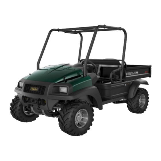
- Page 1 CARRYALL 1500 AWD GASOLINE Operators Manual APPLICABLE TO CARRYALL 1500 AWD FH680D GASOLINE VEHICLES WITH SERIAL PREFIX OF RC...
- Page 2 Copyright © 2020 Club Car, LLC This manual effective July 1, 2020...
-
Page 3: Introduction
INTRODUCTION VEHICLE OWNERSHIP Congratulations! The Club Car brand is widely recognized as the industry leader in vehicle efficiency and long-lasting value. Read, understand, and obey the technical content in this manual to protect your investment and provide years of reliable vehicle operation. Read, understand, and obey all instructions and safety precautions in this manual to prevent the risk of personal injury or property damage. - Page 4 APPROVED DEALERS AND DISTRIBUTORS Club Car’s customer support system offers fast and courteous service. Speak with your dealer or distributor for: • Accessories • Technical Advice • Publications • Warranty Work • Replacement Parts To find your nearest dealer or distributor: •...
- Page 5 NOTICES VEHICLE MODEL AND SERIAL NUMBER The vehicle serial number is located on a bar code decal installed near the accelerator. 1. A two-letter code that identifies the vehicle model. 2. A four-digit code that identifies the model year and production week the vehicle was assembled.
- Page 6 MODIFICATIONS TO THE GOVERNOR WILL VOID THE WARRANTY NOTICE AND DAMAGE THE ENGINE AND OTHER COMPONENTS. DO NOT MODIFY THE GOVERNOR. MODIFICATIONS TO THE VEHICLE MUST NOT COMPROMISE COMPLIANCE WITH STATE OR FEDERAL REGULATIONS. THE DRIVER-SIDE FRAME IS PART OF THE AIR INTAKE SYSTEM. MODIFICATIONS TO THE FRAME CAN DAMAGE THE ENGINE BY CONTAMINATING THE AIR INTAKE SYSTEM.
-
Page 7: Table Of Contents
CONTENTS INTRODUCTION ............................I NOTICES ..............................III SECTION 1 – SAFETY INFORMATION ....................9 General Safety Information ........................ 10 Note To The Owner ......................... 10 Practice Safety..........................10 Safety Signal Words ........................10 Safety Committee .......................... 11 Vehicle Safety Information........................11 Vehicle Safety And Compliance Decals.................. - Page 8 SECTION 4 – VEHICLE FEATURES......................39 Vehicle Features Description ....................... 40 Bucket Seats ............................40 Driver Seat Adjustment ......................... 40 Passenger Seat Adjustment......................40 Electric Bed Lift ............................ 41 Description ............................. 41 Capacity ............................41 Operation............................41 IntelliTrak System..........................42 Modular Cab ............................42 Mud Tire Option ...........................
- Page 9 Vehicle Interior ..........................68 Maintenance Schedule ........................68 Overview............................68 Service Schedule ..........................68 Maintenance Tasks..........................70 Air Filter ............................70 Brake Fluid Level Inspection ......................71 Engine Oil............................72 Front Differential Fluid Level Inspection..................76 Refuel.............................. 77 Lift The Vehicle ..........................78 Lower The Vehicle...........................
- Page 10 Your Warranty Rights And Obligations..................108 Manufacturer’s Warranty Coverage..................... 108 Owner’s Warranty Responsibilities ....................108 Defects Warranty Coverage ......................109 Evaporative Emissions Warranty Parts List ................. 110 CARRYALL 1500 AWD GASOLINE Page viii Operators Manual TPCC01RC00EN019 (Edition C)
-
Page 11: Notices
Safety Information Notices SAFETY INFORMATION CARRYALL 1500 AWD GASOLINE Operators Manual Page 9 TPCC01RC00EN019 (Edition C) -
Page 12: General Safety Information
Safety Information General Safety Information GENERAL SAFETY INFORMATION This vehicle is designed and intended to transport people and cargo in off road applications including commercial, industrial and agriculture. Operation on hard, improved surfaces should be limited. Always adhere to local laws and regulations pertaining to the use of the vehicle. Only operate this vehicle as described in this manual. -
Page 13: Safety Committee
Safety Information Vehicle Safety Information SAFETY SIGNAL WORD SIGNIFICANCE A DANGER identifies a hazardous situation which will result in DANGER death or serious injury. A WARNING identifies a hazardous situation which could result WARNING in death or serious injury. A CAUTION identifies a hazardous situation which could result CAUTION in minor or moderate injury. - Page 14 Safety Information Vehicle Safety Information THE VEHICLE DOES NOT GIVE PROTECTION FROM LIGHTNING, FLYING OBJECTS, OR OTHER STORM RELATED HAZARDS. DO NOT OPERATE THE VEHICLE IN STORMS. STOP THE VEHICLE. GET OUT OF THE VEHICLE IMMEDIATELY AND FIND A SHELTER IN ACCORDANCE WITH APPLICABLE SAFETY GUIDELINES FOR YOUR LOCATION IF IN A STORM.
-
Page 15: Vehicle Safety And Compliance Decals
Safety Information Vehicle Safety Information ACCESSORIES ATTACHED TO THE BED SIDES CAN ADD WIDTH TO THE VEHICLE, HIT NEARBY PERSONS OR OBJECTS, AND CAUSE PROPERTY DAMAGE AND SERIOUS PERSONAL INJURY. USE CAUTION WHEN OPERATING THE VEHICLE WITH ACCESSORIES ATTACHED TO THE BED SIDES. IF THE CAB HAS DAMAGE, DO NOT OPERATE THE VEHICLE. - Page 16 Safety Information Vehicle Safety Information OPERATING INSTRUCTIONS Before using vehicle, read owner’s manual and vehicle safety warnings. Study and understand controls. TO OPERATE • Make sure wheels are turned in desired direction and path is clear. • Place vehicle in NEUTRAL (N) and push the brake pedal. •...
- Page 17 Safety Information Vehicle Safety Information WARNING WARNING • Do not modify or remove Roll-over Protective Structure (ROPS). YOUNG DRIVERS INCREASE CHANCE OF DEATH • Replace ROPS if damaged. Do not attempt repair. UNDER • Young drivers may not be able to control vehicle. •...
-
Page 18: Vehicle Safety Features
Safety Information Vehicle Safety Features WARNING BURN RISK MAXIMUM TONGUE WEIGHT Hot surfaces can cause 150 lb (68 kg) serious burns. Allow to cool before servicing. 101155301 102459001 11. Trailer Hitch Tongue Weight Notice Decal 12. Hot Manifold Warning Decal WARNING WARNING CRUSH HAZARD CAN CAUSE SERIOUS INJURY... -
Page 19: Roll-Over Protective Structure
Safety Information Vehicle Safety Features ROLL-OVER PROTECTIVE STRUCTURE DO NOT REMOVE OR MODIFY ANY COMPONENT OF THE ROLL- DANGER OVER PROTECTIVE STRUCTURE (ROPS). DOING SO WILL RESULT IN VOIDING THE ROPS CERTIFICATION AND COULD WEAKEN THE ROPS, RESULTING IN SERIOUS PERSONAL INJURY OR DEATH. -
Page 20: Cargo Cage Headrest Adjustment
Safety Information Vehicle Safety Features CARGO CAGE HEADREST ADJUSTMENT Remove the thumb screws (1). Adjust the headrest (2). DAMAGE CAN OCCUR IF THE HEADREST HARDWARE IS TOO NOTICE TIGHT. DO NOT TIGHTEN THE HEADREST HARDWARE TOO MUCH. Install and tighten the thumb screws with your hand. FALLING OBJECT PROTECTION SYSTEM The Falling Object Protection System (FOPS) protects the vehicle occupants from falling debris. - Page 21 Safety Information Vehicle Safety Features • Side impacts • Rear impacts • Roll-over PROPER USE OF SEAT BELTS FAILURE TO USE THE SEAT BELT CORRECTLY CAN CAUSE DANGER SERIOUS PERSONAL INJURY OR DEATH. MAKE SURE THAT THE TAB AND BUCKLE ARE LOCKED. MAKE SURE THAT THE BELT IS NOT TWISTED.
- Page 22 Safety Information Vehicle Safety Features SEAT BELT INSPECTION A SEAT BELT THAT DOES NOT OPERATE CORRECTLY CAN CAUSE DANGER SERIOUS PERSONAL INJURY. DO NOT DISASSEMBLE OR CHANGE THE SEAT BELT SYSTEM. DO NOT DAMAGE THE SEAT BELT OR HARDWARE. SPEAK WITH YOUR LOCAL DEALER OR DISTRIBUTOR FOR REPAIR.
-
Page 23: Battery Safety Information
Safety Information Battery Safety Information • Injured Persons - Consult your doctor for specific recommendations. • Seat Belt Extenders - Club Car does not recommend the use of seat belt extenders. LATCH A SEAT BELT AN IMPROPERLY POSITIONED SEAT BELT CAN CAUSE SERIOUS WARNING INJURY OR DEATH IN AN ACCIDENT. -
Page 24: Battery International Safety Symbols
Safety Information Battery Safety Information LOOSE BATTERY WIRES CAN CAUSE A FIRE, PROPERTY DAMAGE, OR SERIOUS PERSONAL INJURY. MAKE SURE THAT ALL BATTERY WIRES AND TERMINALS ARE CLEAN AND TIGHTENED CORRECTLY. BATTERY WIRES WITH DAMAGE OR CORROSION CAN BECOME TOO HOT AND CAUSE A FIRE, PROPERTY DAMAGE, OR SERIOUS PERSONAL INJURY. - Page 25 Safety Information Battery Safety Information Lead-acid batteries and other components which have the Waste Electrical and Electronic Equipment (WEEE) symbol printed on them must be collected and recycled separately from other waste. Do not discard lead-acid batteries as municipal waste. Speak with your dealer or distributor on how to correctly recycle lead-acid batteries.
- Page 26 (Page intentionally left blank.)
-
Page 27: Section 2 - Indicators, Gauges, And Displays
Indicators, Gauges, And Displays Battery Safety Information INDICATORS, GAUGES, AND DISPLAYS CARRYALL 1500 AWD GASOLINE Operators Manual Page 25 TPCC01RC00EN019 (Edition C) -
Page 28: Indicator, Gauge, And Display Locations
Indicators, Gauges, And Displays Indicator, Gauge, And Display Locations INDICATOR, GAUGE, AND DISPLAY LOCATIONS 1. Park Brake Indicator Light 2. Low Oil Warning Light 3. Fuel Gauge/Hour Meter FUEL GAUGE/HOUR METER The fuel gauge/hour meter gives a visual indication of: •... -
Page 29: Park Brake Indicator Light
Indicators, Gauges, And Displays Park Brake Indicator Light STATUS CONDITION Normal Operation When possible: 1. Stop the vehicle. 2. Turn the key to OFF. 3. Examine the engine oil level. 4. Add engine oil as necessary. 5. If the low oil level warning light stays on, have a trained technician examine the vehicle. - Page 30 (Page intentionally left blank.)
-
Page 31: Section 3 - Vehicle Controls
Vehicle Controls Park Brake Indicator Light VEHICLE CONTROLS CARRYALL 1500 AWD GASOLINE Operators Manual Page 29 TPCC01RC00EN019 (Edition C) -
Page 32: Vehicle Controls Locator
Vehicle Controls Vehicle Controls Locator VEHICLE CONTROLS LOCATOR 1. Accelerator Pedal 2. Brake Pedal 3. Park Brake 4. Park Brake Release 5. Steering Column Adjustment Lever 6. Key Switch 7. Forward / Neutral / Reverse Control (FNR) 8. Headlight Switch 9. -
Page 33: Accelerator Pedal
Vehicle Controls Accelerator Pedal ACCELERATOR PEDAL The accelerator pedal is used to increase and maintain the speed of the vehicle. BRAKE PEDAL The brake pedal is used to decrease speed or stop the vehicle. CHOKE POSITION FUNCTION The choke is used to help with engine starts. The choke supplies a richer fuel mixture during ignition when engaged. -
Page 34: Fan Switch
Vehicle Controls Fan Switch FAN SWITCH The fan switch controls the operation of the cab POSITION FUNCTION fan. Medium High FORWARD / NEUTRAL / REVERSE CONTROL FAILURE TO STOP THE VEHICLE BEFORE SHIFTING THE WARNING FORWARD / NEUTRAL / REVERSE CONTROL (FNR) CAN CAUSE PROPERTY DAMAGE AND SERIOUS PERSONAL INJURY. -
Page 35: Headlight Switch
Vehicle Controls Headlight Switch HEADLIGHT SWITCH The headlight switch controls the operation of the POSITION FUNCTION headlights. Bottom HORN The horn button is used to control the horn. The horn button is spring loaded to stay in the off position. Push and hold the horn button to operate the horn. INTELLITRAK SWITCH KEY SWITCH THE KEY SWITCH CAN BE USED TO DISABLE THE ENGINE IN AN... -
Page 36: Park Brake
Vehicle Controls Park Brake POSITION CONDITION Normal position when the vehicle is not in use. Electrical power from the battery is not available to power the engine, engine starter, or electrical systems. Note: Some electrical accessories operate independently of the key switch. Normal position when the vehicle is in use. -
Page 37: Turn Signal Lever
Vehicle Controls Turn Signal Lever The steering column adjustment lever adjusts the steering column. Set the lever in the down position to unlock and adjust the steering column position. Set the lever in the up position to lock the steering column. TURN SIGNAL LEVER The turn signal lever controls the operation of the POSITION... -
Page 38: Lower Dash Fan Switch
Vehicle Controls Modular Cab Controls The dome light switch controls the operation of POSITION FUNCTION the interior cabin lights. Note: The dome light operates independently of the key switch position. LOWER DASH FAN SWITCH POSITION FUNCTION The lower dash fan switch controls the operation of the lower dash fan. -
Page 39: Windshield Washer Switch
Vehicle Controls Modular Cab Controls WINDSHIELD WASHER SWITCH The windshield washer switch controls the operation of the washer fluid supply to the windshield. The switch is spring loaded to stay in the off position. Push and hold the switch in the on position to apply washer fluid to the windshield. CARRYALL 1500 AWD GASOLINE Operators Manual Page 37... - Page 40 (Page intentionally left blank.)
-
Page 41: Section 4 - Vehicle Features
Vehicle Features Modular Cab Controls VEHICLE FEATURES CARRYALL 1500 AWD GASOLINE Operators Manual Page 39 TPCC01RC00EN019 (Edition C) -
Page 42: Vehicle Features Description
Vehicle Features Vehicle Features Hazard Statements The vehicle features listed are standard and optional. BUCKET SEATS DRIVER SEAT ADJUSTMENT DO NOT ADJUST THE DRIVER-SIDE SEAT WHILE THE VEHICLE IS WARNING IN MOTION. Pull the driver seat adjustment lever (1) to the left. Adjust the driver seat forward or rearward. -
Page 43: Electric Bed Lift
Vehicle Features Electric Bed Lift Align the mounting plate (4) holes with the holes in the passenger seat. Install the washers and bolts. Tighten the bolts to 80 lb·in (9.0 N·m). Install the passenger seat. Make sure that the passenger seat is engaged. ELECTRIC BED LIFT USE CAUTION WHEN WORKING UNDER THE BED. -
Page 44: Intellitrak System
Vehicle Features IntelliTrak System INTELLITRAK SYSTEM IntelliTrak is an on-demand all-wheel drive traction control system. IntelliTrak system supplies power from wheels that have lost traction to wheels that have traction. Speak with your local approved dealer or distributor for a detailed system description and demonstration. MODULAR CAB The modular cab is available in different configurations for a wide range of operator requirements. -
Page 45: Operation
Vehicle Features Tilt Cargo Bed OPERATION LIFT THE TILT CARGO BED Disable the vehicle. Pull the bed latch handle. Lift the bed. Make sure that the prop rod (1) is in a notch (2). LOWER THE TILT CARGO BED Lift the tilt cargo bed. CARRYALL 1500 AWD GASOLINE Operators Manual Page 43... -
Page 46: 12-Volt Power Receptacle
Vehicle Features 12-Volt Power Receptacle Remove the prop rod (1) from the notch (2). Lower the tilt cargo bed. Make sure that the cargo bed latch engages. 12-VOLT POWER RECEPTACLE The 12-volt 6.5-amp power receptacle supplies electricity to power and charge accessories when the key switch is ON. -
Page 47: Section 5 - Vehicle Specifications
Vehicle Specifications Winch VEHICLE SPECIFICATIONS CARRYALL 1500 AWD GASOLINE Page 45 Operators Manual TPCC01RC00EN019 (Edition C) -
Page 48: Dimensions
Vehicle Specifications Dimensions DIMENSIONS 122 in (309.9 cm) - box bed configuration without a Length brushguard 58.5 in (148.5 cm) - without mirror Width 63.6 in (161.5 cm) - with mirror 82.3 in (209 cm) - with ROPS Height 34 in (86.4 cm) Bed Height 48.0 x 49.8 x 10.9 in (122 x 127 x 28 cm) Box Bed Size... -
Page 49: Gasoline Engine
Vehicle Specifications Gasoline Engine GASOLINE ENGINE Horsepower Rating 20 hp (15 kW) at 3400 rpm (per SAE J1349) Fuel Type Gasoline with less than 10% ethanol rating Fuel Capacity 6.5 gal (24.6 l) Engine Oil Capacity 1.6 qt (1.5 l) BATTERY Battery Type 12V top-post, no-maintenance... - Page 50 Vehicle Specifications Vehicle Weights And Load Capacities TOO MUCH WEIGHT IN THE VEHICLE CAN AFFECT THE VEHICLES HANDLING, OR CAUSE COMPONENT FAILURE, RESULTING IN LOSS OF CONTROL OF VEHICLE AND SERIOUS PERSONAL INJURY. DO NOT EXCEED THE VEHICLE LOAD CAPACITIES. DO NOT TOW WHEN THE CARGO CAPACITY IS EXCEEDED.
- Page 51 Vehicle Specifications Vehicle Weights And Load Capacities TERM DEFINITION Vehicle Rated The vehicle rated capacity is the maximum weight on the vehicle. This capacity Capacity includes the weight of: bed load, cargo, occupants, and optional equipment. The vehicle combination rated capacity is the maximum weight on the vehicle Vehicle Combination Rated with a trailer.
- Page 52 (Page intentionally left blank.)
-
Page 53: Section 6 - Vehicle Operation
Vehicle Operation Vehicle Weights And Load Capacities VEHICLE OPERATION CARRYALL 1500 AWD GASOLINE Page 51 Operators Manual TPCC01RC00EN019 (Edition C) - Page 54 Vehicle Operation Vehicle Operations Hazard Statements OPERATING THE VEHICLE WHILE OCCUPANTS ARE NOT FULLY DANGER SEATED CAN CAUSE SERIOUS PERSONAL INJURY OR DEATH. START THE VEHICLE ONLY WHEN ALL OCCUPANTS ARE FULLY SEATED WITH SEAT BELTS FASTENED. DO NOT LET PASSENGERS RIDE IN THE CARGO BED. FALLING OBJECTS CAN CAUSE PROPERTY DAMAGE, SERIOUS WARNING PERSONAL INJURY, OR DEATH.
-
Page 55: Daily Pre-Operational Safety And Performance Checks
Vehicle Operation Daily Pre-Operational Safety And Performance Checks A SHARP TURN AT HIGH SPEEDS CAN CAUSE A ROLL-OVER OR FALLING OFF WHICH CAN RESULT IN PROPERTY DAMAGE, AND SERIOUS PERSONAL INJURY. OPERATE THE VEHICLE SLOWLY IN TURNS. UNINTENDED VEHICLE OPERATION CAN CAUSE SERIOUS PERSONAL INJURY OR DEATH. -
Page 56: Daily Pre-Operational Safety Checklist
Vehicle Operation Daily Pre-Operational Safety And Performance Checks DAILY PRE-OPERATIONAL SAFETY CHECKLIST INSPECTION INSPECTION CRITERIA AREA • Make sure that all parts are correctly installed. • Make sure that all nuts, bolts, and screws are tight. General • Replace missing, worn, or damaged items. •... -
Page 57: Vehicle Performance Inspection
Vehicle Operation Daily Pre-Operational Safety And Performance Checks INSPECTION INSPECTION CRITERIA AREA Engine Air Filter • Examine the air filter. Replace if dirty or damaged. Hydraulic Brakes • Examine the brake fluid level. Add brake fluid (DOT 5 only) as necessary. Vehicle Performance •... -
Page 58: Vehicle Movement
Vehicle Operation Vehicle Movement Slowly push the accelerator pedal. Make sure that the vehicle moves forward. Operate the vehicle to full speed. Release the accelerator pedal. Make sure: 11.A The accelerator pedal goes back to its initial position. 11.B The engine idles. Slowly push the brake pedal. -
Page 59: Turn Off Engine
Vehicle Operation Vehicle Movement • Make sure that all passengers are seated with their seat belt fastened and use the hand holds or handrails. The operator must have both hands on the steering wheel. • Front wheels are turned in the direction of travel. •... -
Page 60: Reverse Movement
Vehicle Operation Vehicle Movement • Read and obey all safety decals and information located on the vehicle. • Understand how to operate the vehicle correctly and safely. • Understand the function of all vehicle controls, indicators, displays, and gauges. • Make sure that all passengers are seated with seat belts fastened (if equipped) and use the hand holds or handrails. -
Page 61: Park The Vehicle
Vehicle Operation Driving Conditions Push the brake pedal. PARK THE VEHICLE Stop the vehicle. Engage the park brake to prevent vehicle movement. Set the Forward / Neutral / Reverse control (FNR) to N. Turn the key to OFF. Remove the key. Keep the key in a safe area. DRIVING CONDITIONS UPHILL SLOPE VEHICLE ROLL-OVER CAN CAUSE SERIOUS PERSONAL INJURY... -
Page 62: Side Hill Slope
Vehicle Operation Driving Conditions SIDE HILL SLOPE TO PREVENT ROLL-OVER, PROPERTY DAMAGE, AND SERIOUS WARNING PERSONAL INJURY, OPERATE THE VEHICLE SLOWLY ON A SLOPE. VEHICLE ROLLBACK WHEN STARTING ON AN INCLINE CAN CAUSE PROPERTY DAMAGE, SERIOUS PERSONAL INJURY, OR DEATH. USE THE BRAKE PEDAL TO HOLD THE VEHICLE UNTIL THE DRIVETRAIN IS FULLY ENGAGED. -
Page 63: Over Obstacles
Vehicle Operation Driving Conditions • Prevent driving at an offset angle. An offset angle will cause the vehicle to lean sharply to one side. • Continue at a stable rate of speed. Do not accelerate quickly. • Decrease the vehicle speed. •... -
Page 64: Through Water
Vehicle Operation Driving Conditions • Look forward and learn to read the terrain. Be constantly alert for hazards. • Drive slowly and use caution when operating on unfamiliar terrain. Not all obstacles are immediately visible. THROUGH WATER DRIVING THROUGH WATER CAN DECREASE BRAKE WARNING PERFORMANCE. - Page 65 Vehicle Operation Driving Conditions • Secure all loads before operating. Unsecured loads can cause unstable operating conditions, which could cause loss of vehicle control. • Operate only with stable and safely arranged loads. When handling off-centered loads that cannot be centered, correctly fasten the load and operate with extra caution. Always attach the tow load to the hitch point designated for the vehicle.
- Page 66 (Page intentionally left blank.)
-
Page 67: Section 7 - Vehicle Maintenance
Vehicle Maintenance Driving Conditions VEHICLE MAINTENANCE CARRYALL 1500 AWD GASOLINE Operators Manual Page 65 TPCC01RC00EN019 (Edition C) - Page 68 Vehicle Maintenance Vehicle Maintenance Hazard Statements FUEL IS FLAMMABLE AND EXPLOSIVE. DO NOT SMOKE. KEEP DANGER SPARKS AND OPEN FLAMES AWAY FROM THE VEHICLE AND SERVICING AREA. DO THE SERVICING OF THE VEHICLE IN A VENTILATED AREA. INCORRECT OPERATION OF THE CARGO BED CAN CAUSE SERIOUS PERSONAL INJURY OR DEATH.
-
Page 69: Disable The Vehicle
Vehicle Maintenance Disable The Vehicle LIFT ONLY ONE END OF THE VEHICLE AT A TIME. USE A SUITABLE LIFTING DEVICE WITH 1000 LB (454 KG) MINIMUM LIFTING CAPACITY. DO NOT USE THE LIFTING DEVICE TO HOLD THE VEHICLE IN THE LIFTED POSITION. USE APPROVED JACK STANDS OF PROPER WEIGHT CAPACITY TO SUPPORT THE VEHICLE AND CHOCK THE WHEELS THAT REMAIN ON THE FLOOR. -
Page 70: Vehicle Interior
Vehicle Maintenance Maintenance Schedule Use non-abrasive wax products. Battery acid, fertilizers, tars, asphalt, creosote, paint, or chewing gum should be removed immediately to prevent possible stains. Discard the waste water correctly. CLEANING THE VEHICLE INTERIOR MOISTURE CAN CAUSE ELECTRICAL COMPONENT DAMAGE. DO NOTICE NOT USE A PRESSURE WASHER OR STEAM CLEANER TO CLEAN THE VEHICLE. - Page 71 Vehicle Maintenance Maintenance Schedule INTERVAL DESCRIPTION Do the Daily Pre-Operational Safety Check. Do the Daily Vehicle Performance Inspection. Daily Examine the engine oil level. Examine the brake fluid level. Make sure that the brake pedal operates correctly. Examine the tire pressure. Examine the engine air passage.
-
Page 72: Maintenance Tasks
Vehicle Maintenance Maintenance Tasks INTERVAL DESCRIPTION Examine the vehicle for loose hardware. Tighten as necessary. Replace the air filter. If the vehicle is operated in dirty environments, replace the air filter more frequently Examine the air filter hose for damage. Make sure the air filter hose clamps are tight. -
Page 73: Brake Fluid Level Inspection
Vehicle Maintenance Maintenance Tasks Release the wire latches (1). Remove the air cleaner cover (2). Remove the air filter (3). AIR FILTER INSTALLATION Use a wet lint-free cloth to clean the inside of the air filter container. Install the air filter (3). Install the air cleaner cover (2). -
Page 74: Engine Oil
Vehicle Maintenance Maintenance Tasks If the brake fluid level is below the minimum indicator, have a trained technician do a check of the brake system. ENGINE OIL ENGINE OIL VISCOSITY Select the engine oil viscosity for your environmental conditions. CARRYALL 1500 AWD GASOLINE Page 72 Operators Manual TPCC01RC00EN019 (Edition C) - Page 75 Vehicle Maintenance Maintenance Tasks ENGINE OIL LEVEL INSPECTION Before the engine oil is examined: • Disable the vehicle. To examine the engine oil: Remove the dipstick (1). Make sure that there is oil on the dipstick. Install the dipstick. Start and operate the engine for three minutes. If the low oil warning light stays on, turn off the engine immediately.
- Page 76 Vehicle Maintenance Maintenance Tasks Turn off the engine. Wait two minutes. Remove and clean the dipstick. Install the dipstick. Remove the dipstick. Make sure that the oil level is between the maximum (1) and minimum (2) indicators. If the oil level is below the minimum indicator, add engine oil. Install the dipstick.
- Page 77 Vehicle Maintenance Maintenance Tasks Remove the oil fill cap (1). Clean the area around the oil drain plug (2) and oil filter (3). Put a drain pan below the oil drain plug. Remove the oil drain plug. Drain the oil fully. Clean the oil drain plug.
-
Page 78: Front Differential Fluid Level Inspection
Vehicle Maintenance Maintenance Tasks Speak with your dealer or distributor to get more information on how to recycle the used engine oil and filter correctly. ADD ENGINE OIL DO NOT REMOVE THE DIPSTICK WHILE THE ENGINE IS ON. CAUTION TOO MUCH ENGINE OIL CAN DECREASE ENGINE PERFORMANCE NOTICE AND DAMAGE THE ENGINE. -
Page 79: Refuel
Vehicle Maintenance Maintenance Tasks Remove the plug (1). Make sure that the fluid level is at the bottom of the hole. If the fluid level is low, add recommended fluid until the fluid level is at the bottom of the hole. Apply Loctite 567 on the threads of the plug. -
Page 80: Lift The Vehicle
Vehicle Maintenance Maintenance Tasks A FUEL WITH AN ALCOHOL CONTENT THAT EXCEEDS 10% BY NOTICE VOLUME (LIKE E15 AND E85) WILL CAUSE VEHICLE DAMAGE AND VOID THE WARRANTY. ONLY USE THE RECOMMENDED FUEL TYPE. Turn the key to OFF. Let the engine cool. Remove the fuel fill cap (1). - Page 81 Vehicle Maintenance Maintenance Tasks Place the jack in the center of the lift point. Lift the front of the vehicle. Put jack stands under the frame rails. Lower the vehicle onto the jack stands. LIFT THE REAR OF THE VEHICLE LIFTING THE VEHICLE WITH CARGO CAN CAUSE PROPERTY WARNING DAMAGE, SERIOUS PERSONAL INJURY, OR DEATH.
-
Page 82: Lower The Vehicle
Vehicle Maintenance Maintenance Tasks Place the jack in the center of the lift point. Lift the rear of the vehicle. Put jack stands under the frame rails. Lower the vehicle onto the jack stands. LOWER THE VEHICLE LOWER THE FRONT OF THE VEHICLE Before the front of the vehicle is lowered: •... - Page 83 Vehicle Maintenance Maintenance Tasks To lower the front of the vehicle: Place the jack in the center of the lift point. Lift the vehicle off of the jack stands. Remove the jack stands. Lower the vehicle. LOWER THE REAR OF THE VEHICLE Before the rear of the vehicle is lowered: •...
-
Page 84: Rear Differential Fluid Level Inspection
Vehicle Maintenance Maintenance Tasks To lower the rear of the vehicle: Place the jack in the center of the lift point. Lift the vehicle off of the jack stands. Remove the jack stands. Lower the vehicle. REAR DIFFERENTIAL FLUID LEVEL INSPECTION [SampleTaskID] Disable the vehicle. -
Page 85: Spark Plug
Vehicle Maintenance Maintenance Tasks Make sure that the fluid level is at the bottom of the hole. If the fluid level is low, add recommended fluid until the fluid level is at the bottom of the hole. Apply Loctite® 567 on the threads of the plug. Install the plug. -
Page 86: Tire Pressure Measurement
Vehicle Maintenance Maintenance Tasks Connect the spark plug wires (1). Connect the battery. TIRE PRESSURE MEASUREMENT Before the tire pressure measurement: • Disable the vehicle. To measure the tire pressure: Remove the valve stem cap. Use a pressure gauge to measure the tire pressure. Adjust to meet the recommended tire pressure. -
Page 87: Wheel Assembly
Vehicle Maintenance Maintenance Tasks WHEEL ASSEMBLY WHEEL ASSEMBLY REMOVAL Before the wheel assembly is removed: • Disable the vehicle. To remove the wheel assembly: Remove the wheel cover. Loosen the lug nuts. Lift the vehicle to allow for removal of the wheel assembly. Remove the lug nuts. - Page 88 (Page intentionally left blank.)
-
Page 89: Section 8 - Battery Maintenance
Battery Maintenance Maintenance Tasks 316V BATTERY MAINTENANCE CARRYALL 1500 AWD GASOLINE Operators Manual Page 87 TPCC01RC00EN019 (Edition C) -
Page 90: Battery Cleaning
Battery Maintenance Battery Maintenance Hazard Statements ELECTRICAL SHORTS CAN CAUSE A FIRE, ELECTRICAL SHOCK, WARNING SERIOUS PERSONAL INJURY, OR DEATH. PREVENT CONTACT BETWEEN POSITIVE VOLTAGE AND THE GROUND CIRCUIT. USE INSULATED TOOLS. WEAR SAFETY GLASSES OR APPROVED EYE PROTECTION WHEN CAUTION YOU DO THE SERVICING OF THE VEHICLE. -
Page 91: Battery Electrical Connection
Battery Maintenance Battery Electrical Connection BATTERY ELECTRICAL CONNECTION DISCONNECT THE BATTERY Before the battery is disconnected: • Disable the vehicle. To disconnect the battery: Disconnect the negative (–) cable (1). Disconnect the positive (+) cable (2). CONNECT THE BATTERY Connect the positive (+) cable (2). Connect the negative (–) cable (1). - Page 92 (Page intentionally left blank.)
-
Page 93: Section 9 - Transport And Tow
Transport And Tow Battery Electrical Connection TRANSPORT AND TOW CARRYALL 1500 AWD GASOLINE Operators Manual Page 91 TPCC01RC00EN019 (Edition C) -
Page 94: Prepare The Vehicle To Be Towed
Transport And Tow Transport And Tow Hazard Statements DO NOT LET PASSENGERS RIDE IN THE VEHICLE OR TRAILER DANGER BEING TOWED. KEEP AWAY FROM THE AREA BETWEEN THE TOW VEHICLE AND WARNING THE TOWED VEHICLE OR TRAILER. DO NOT TOW A CLUB CAR VEHICLE BEHIND A PASSENGER VEHICLE OR TRUCK ON A PUBLIC ROAD. -
Page 95: Towing A Trailer Or Vehicle
Transport And Tow Towing A Trailer Or Vehicle TOWING A TRAILER OR VEHICLE USE EXTREME CAUTION WHEN TOWING A TRAILER OR VEHICLE. CAUTION DO NOT MAKE SHARP TURNS WHEN TOWING A TRAILER OR VEHICLE. DO NOT TOW A TRAILER OR VEHICLE ON PUBLIC ROADS OR HIGHWAYS. -
Page 96: Vehicle Transport Recovery
Transport And Tow Vehicle Transport Recovery VEHICLE TRANSPORT RECOVERY Make sure that the trailer is correctly configured to remove the vehicle from the trailer safely. Remove all materials used to secure the vehicle to the trailer. Examine the vehicle for loose parts. Tighten as necessary. Install the windshield. -
Page 97: Section 10 - Extended Storage
Extended Storage Vehicle Transport Recovery EXTENDED STORAGE CARRYALL 1500 AWD GASOLINE Operators Manual Page 95 TPCC01RC00EN019 (Edition C) -
Page 98: Extended Storage Preparation
Extended Storage Extended Storage Hazard Statements FUEL IS FLAMMABLE AND EXPLOSIVE. DO NOT OPERATE THE DANGER VEHICLE WHEN FUEL IS SPILLED. CORRECTLY CLEAN THE SPILLED FUEL. FUEL IS FLAMMABLE AND EXPLOSIVE. DO NOT DRAIN FUEL WHEN THE ENGINE IS ON. FUEL IS FLAMMABLE AND EXPLOSIVE. - Page 99 Extended Storage Extended Storage Preparation Turn the key to OFF. Remove the key. Keep the key in a safe area. Put chocks against the wheels. Note: Do not engage the park brake. Remove all cargo and personal items. Fill the fuel tank. Add a fuel stabilizer.
-
Page 100: Return To Service From Extended Storage
Extended Storage Return To Service From Extended Storage 16.E Turn the engine crankshaft by hand several times. 16.F Apply a thin layer of high temperature anti-seize lubricant to the spark plug threads. 16.G Use a spark plug socket to install and tighten the spark plugs to 16 lb·ft (22 N·m). 16.H Connect the spark plug wires. - Page 101 Extended Storage Return To Service From Extended Storage A NOT FULLY OPEN FUEL SHUTOFF VALVE AND THE USE OF THE NOTICE CHOKE CAN CAUSE SPARK PLUG AND ENGINE DAMAGE. MAKE SURE THAT THE VALVE IS FULLY OPEN. Turn the fuel shutoff valve (1) to ON. Start and run the engine.
- Page 102 (Page intentionally left blank.)
-
Page 103: Section 11 - Warranties
Warranties Return To Service From Extended Storage WARRANTIES CARRYALL 1500 AWD GASOLINE Operators Manual Page 101 TPCC01RC00EN019 (Edition C) -
Page 104: Limited Warranty
Warranties Limited Warranty LIMITED WARRANTY WARRANTY Club Car, LLC (“Club Car”) hereby warrants to the original purchaser or lessee, as those terms are defined herein, and subject to the provisions, limitations and exclusions in this limited warranty, that its new vehicle or new component purchased from Club Car or an Authorized Dealer or Distributor shall be free from defects in material and workmanship under normal use and service for the periods stated below, subject to the provisions, limitations and exclusions in this limited warranty. -
Page 105: Exclusions
Warranties Limited Warranty EXCLUSIONS Excluded from any Club Car warranty is damage to a vehicle or component resulting from a cause other than a defect including poor maintenance, neglect, abuse, accident and collision, maintenance adjustments, unreasonable or unintended strain or use, improper installation of accessories, installation of parts or accessories that are not original equipment including Club Car approved or non- approved GPS systems, non-approved alteration, and acts of God. -
Page 106: Sole Remedy
Warranties Limited Warranty maintenance as outlined in the operator’s manual and maintenance and service manual was not performed at the time and in the manner specified in such manuals. SOLE REMEDY Club Car’s liability under this limited warranty or in any action whether based upon warranty, contract, negligence, strict product liability or otherwise, shall be the repair or replacement, at Club Car’s option, of the vehicle or component thereof that Club Car deems to be defective. -
Page 107: Federal Emissions Component Defect Warranty
Warranties Federal Emissions Component Defect Warranty E-mail cci_warrantyadministration@clubcar.com Postal Service Club Car, LLC Attention: Warranty Services 4125 Washington Rd. Evans, Georgia 30809 United States Of America FEDERAL EMISSIONS COMPONENT DEFECT WARRANTY WARRANTY COVERAGE This emission warranty is applicable in all States in the United States Of America, except the State of California. -
Page 108: Distribution Center
Warranties Federal Emissions Component Defect Warranty – Air filter • Ignition System – Spark plugs – Magneto or electronic ignition system – Spark advance/retard system, if applicable • Catalyst or Thermal Reactor System – Exhaust Manifold, if applicable • Miscellaneous Items Used in Above Systems –... -
Page 109: What Is Not Covered
Warranties Federal Emissions Component Defect Warranty • pay for the shipping costs of replacement parts to and from an authorized service center • provide for a service technician to come to the owner to make the warranty repair • pay for the repair to be made at a local non-authorized service center WHAT IS NOT COVERED •... -
Page 110: How To Make A Claim
Warranties California Evaporative Emission Control Warranty Statement If other than the parts authorized by Club Car are used for maintenance replacements or for the repair of components affecting emission control, you should assure yourself that such parts are warranted by their manufacturer to be equivalent to the parts authorized by Club Car in their performance and durability. -
Page 111: Defects Warranty Coverage
Warranties California Evaporative Emission Control Warranty Statement E-mail cci_warrantyadministration@clubcar.com Postal Service Club Car, LLC Attention: Warranty Services 4125 Washington Rd. Evans, Georgia 30809 United States Of America DEFECTS WARRANTY COVERAGE Club Car warrants to the ultimate purchaser and each subsequent purchaser that the small off-road engines (“SORE”) and related evaporative emissions control equipment is designed, built and equipped so as to conform with all applicable California environmental emission regulations;... -
Page 112: Evaporative Emissions Warranty Parts List
Warranties California Evaporative Emission Control Warranty Statement 9. Any replacement part may be used in the performance of any warranty maintenance or repairs and must be provided without charge to the owner. Such use will not reduce the warranty obligations of Club Car. - Page 113 Warranties California Evaporative Emission Control Warranty Statement • Valves, hosing, tubing, fittings, seals, gaskets, clamps, and fittings as they relate to the evaporative emissions control system. CARRYALL 1500 AWD GASOLINE Page 111 Operators Manual TPCC01RC00EN019 (Edition C)
- Page 114 (Page intentionally left blank.)
- Page 115 (Page intentionally left blank.)
- Page 116 Publication Part Number TPCC01RC00EN019 Edition Code Club Car, LLC www.clubcar.com Phone 1 706 258 2225 P.O. Box 204658 1 800 ClubCar Augusta, GA 30917-4658 1 706 863 5858...
Need help?
Do you have a question about the Club Car CARRYALL 1500 AWD FH680D and is the answer not in the manual?
Questions and answers