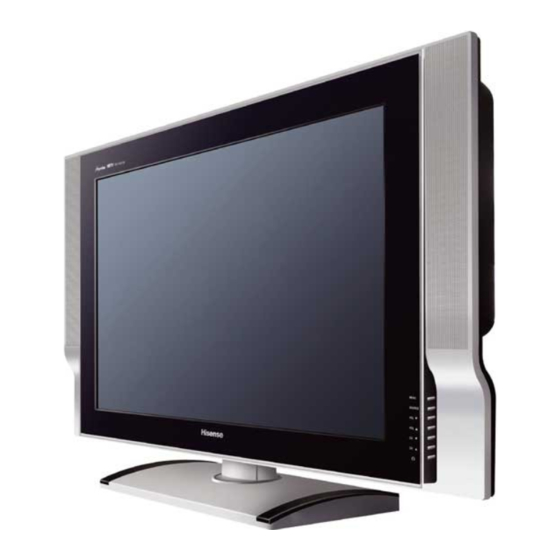
Summary of Contents for Hisense LCD3203EU
- Page 1 All manuals and user guides at all-guides.com LCD3203EU SERVICE MANUAL (V1.0) January 2005...
-
Page 2: Table Of Contents
All manuals and user guides at all-guides.com CONTENTS 1. SAFETY PRECAUTION……………………………………………………….………3 2. PRODUCT SAFETY NOTICE…………………………………………………………3 3. BLOCK DIAGRAM…………………………………..………………………………..4 4. FUNCTION OF CONJUNCTIONS………………………………………….………. .5 5. SIGNAL DIAGRAM…………………………………..………………………………..9 TROUBLESHOOTING………………………………………………………………..10 7. SERVICE MODE MENU………………..……………………………….……………..11 8. PART LIST……………..…………………………..…………………….……………..12... -
Page 3: Safety Precaution
All manuals and user guides at all-guides.com CAUTION: BEFORE SERVICING THE CHASSIS, READ THE “SAFETY PRECAUTION” “PRODUCT SAFETY NOTICE”ON PAGE 1 OF THIS MANUAL. SAFETY PRECAUTION WARNING: Service should not be attempted by anyone unfamiliar with the necessary precaution on thisreceiver. -
Page 4: Block Diagram
All manuals and user guides at all-guides.com BLOCK DIAGRAM SCART OUTPUT REMOTE BOARD(466A) BOARD(467A) SP303 SP305 SP302 SP304 XP08 4(earphone line) XP616 XP617 XP612 XP613 XP609 XP606 TUNE XP611 BOARD (393A) XP608 XP610 XP607 MAIN BOARD (530) XP15 XP17 XP16 Inverter XPE003 XPE001... -
Page 5: Function Of Conjunctions
All manuals and user guides at all-guides.com FUNCTION OF CONJUNCTIONS XPE003---XP16 ITEM NAME FUNCTION +12V Panel power +12V Panel power Main board power(no use ) Main board power(no use ) POWER_ON Control POWER to standby XPE001---XP15 ITEM NAME FUNCTION +5V_M Main board power +5V_M Main board power... - Page 6 All manuals and user guides at all-guides.com SCART2 identify automatically SDA5550 reset XP4---XP607 ITEM NAME FUNCTION C_IN SCART2 C input Y_IN SCART2 Y input SCART1 AV input SCART2 AV input TV_IN TV from TUNER HDTV component input HDTV component input HDTV component input XP6---XP610 ITEM...
- Page 7 All manuals and user guides at all-guides.com XP12 ITEM NAME FUNCTION TXA0- LVDS signal TXA0+ LVDS signal TXA1- LVDS signal TXA1+ LVDS signal TXA2- LVDS signal TXA2+ LVDS signal TXAC- LVDS signal TXAC+ LVDS signal TXA3- LVDS signal TXA3+ LVDS signal +12V +12V +12V...
- Page 8 All manuals and user guides at all-guides.com Power indicator light XPE005、XPE006 ITEM NAME FUNCTION Power Supply+24V Power Supply+24V Power Supply+24V Power Supply+24V Power Supply+24V Luminance regulation 0V~3.3V 0V~3.3V On/Off Backlight On~Off 0V~5V 0V~5V XPE004---XP611 ITEM NAME FUNCTION +15V TDA7266 power +15V TDA7266 power +12V...
-
Page 9: Signal Diagram
All manuals and user guides at all-guides.com SIGNAL DIAGRAM MUTE V603 V604 A600 N600 N603 2SIF MSP3410 TDA7266B TUNER N604 TDA2822 N605 SDA5550 CVBS LVDS VPC3230 GM1501 VIDEO(SCART) PI5V330 S-VIDEO(SCART2) N601 PI5V330 YPbPr RGB(SCART1) -
Page 10: Troubleshooting
All manuals and user guides at all-guides.com TROUBLESHOOTING NO PICTURE is there noise Antrnna/cable tuner board picture? Check the Antrnna/cable connection indicator light blue? Check the main board blue there Check the signal connection signal ? HDTV OK? Tuner board is Main board is... -
Page 11: Service Mode Menu
All manuals and user guides at all-guides.com SERVICE MODE MENU You can entry service mode menu by two methods: 1、[MUTE]+[5]: Press [MUTE] button, and then press number [5] button at once. 2、[DISPLAY]+[MUTE]: Firstly, adjust the number of volume to 2. Press [display] button, and then press [MUTE] before display on screen disappear. -
Page 12: Part List
All manuals and user guides at all-guides.com PART LIST 一、MAIN BOARD PART ITEM NAME CATALOG NO. AMOUNT UNIT LOCATION RSAG7.820.530 Rectangular RC0603JR-07-0R0 R11 R13 R28 R29 Chip R30 R44 R47 R49 Resistor R78 R79 Rectangular RC0603JR-07-22R R19 R20 R24 R34 Chip Resistor Rectangular... - Page 13 All manuals and user guides at all-guides.com Rectangular RC0603JR-07-3K3 R62 R74 Chip Resistor Rectangular RC0603JR-07-4K7 R70 R71 R88 R89 Chip Resistor Rectangular RC0603JR-07-10K R1 R12 R2 R3 R4 R43 Chip R5 R61 R65 R75 R77 Resistor R82 R83 R86 R90 R91 R92 Rectangular RC0603JR-07-47K...
- Page 14 All manuals and user guides at all-guides.com Ceramic B102 Capacitor Chip CC0603KRX7R9B C14 C23 C40 C55 Ceramic B152 Capacitor Chip CC0603KRX7R9B C10 C11 C25 C5 C6 Ceramic B103 C7 C8 C9 Capacitor Chip CC0603KRX7R9B C16 C29 C47 Ceramic B473 Capacitor Chip CC0603KRX7R7B C48 C49 C50...
- Page 15 All manuals and user guides at all-guides.com C182 C183 C184 C185 C186 C187 C189 C191 C162 C164 C165 C166 C168 C169 C170 C173 C153 C155 C156 C157 C158 C159 C160 C161 C145 C146 C147 C148 C15 C150 C151 C152 Chip CC0603KRX7R6B C24 C57 C58 C59 Ceramic...
- Page 16 All manuals and user guides at all-guides.com Inductor L26 L27 L28 L29 L30L31 L32 L33 L34 L35 L36 Surface BAV99T116 VD1 VD2 VD3 VD4 Mount VD5 VD6 VD7 VD8 Diodes Surface SST3904T116 V1 V3 V4 V5 V6 Mount NPN Transistor CHIP IRF7314 Integrated...
- Page 17 All manuals and user guides at all-guides.com Circuit CHIP SN74LVC14APWR 1 Integrated Circuit CHIP DS1818R-10 Integrated Circuit CHIP PI5V330Q Integrated Circuit CHIP BR24C21F Integrated Circuit CRYSTAL JAS14C OSCILLAT CRYSTAL JAS20K OSCILLAT...
- Page 18 All manuals and user guides at all-guides.com 二、TUNE BOARD PAART LIST ITEM NAME CATALOG NO. AMOUNT UNIT LOCATION E/RSAG7.820.393A Rectangular RC0805JR-07-0R0 R630 R658 Chip R683 R684 Resistor R704 R705 R706 R707 L614 L615 L616 L617 R602 R603 R608 R626 R717 R718 R724 R727...
- Page 19 All manuals and user guides at all-guides.com Rectangular RC0805JR-07-4K7 R643 R698 Chip R699 Resistor Rectangular RC0805JR-07-6K8 R604 R625 Chip R676 R677 Resistor R678 R679 Rectangular RC0805JR-07-10K R609 R610 Chip R612 R613 Resistor R617 R618 R619 R622 R635 R640 R646 R686 R687 Rectangular RC0805JR-07-22K...
- Page 20 All manuals and user guides at all-guides.com C691 C704 Chip CC0805KRX7R9BB4 C721 C722 Ceramic Capacitor Chip CC0805KRX7R9BB1 C616 Ceramic Capacitor Chip CC0805KRX7R9BB1 C638 C661 Ceramic C667 C668 Capacitor C669 C672 C679 C680 C603 C604 C606 C618 C623 C629 C631 C637 C681 C682 C683...
- Page 21 All manuals and user guides at all-guides.com C720 Electrolytic CD110-25V-47u-M C624 C625 Capacitor C643 C677 C710 C718 Electrolytic CD110-25V-100u-M C671 C674 Capacitor C675 C676 C688 C725 Electrolytic CD110-25V-470u-M C607 C659 Capacitor C662 Inductor LGB0606-10u-J L600 L601 L606 SWITCH IN4148 VD600 VD601 DIODES VD602 VD603 VD604...


Need help?
Do you have a question about the LCD3203EU and is the answer not in the manual?
Questions and answers
Why does it say no cable connected