
Related Manuals for Siemens SIMATIC NET RUGGEDCOM i801


Summary of Contents for Siemens SIMATIC NET RUGGEDCOM i801
- Page 1 Installation Manual SIMATIC NET Rugged Ethernet Switches RUGGEDCOM i801 Edition 01/2021 https://www.siemens.com...
- Page 2 Preface Introduction Installing the Device SIMATIC NET Device Management Rugged Ethernet Switches RUGGEDCOM i801 Communication Ports Technical Specifications Installation Manual Certification 01/2021 C79000-G8976-1003-06...
- Page 3 Note the following: WARNING Siemens products may only be used for the applications described in the catalog and in the relevant technical documentation. If products and components from other manufacturers are used, these must be recommended or approved by Siemens. Proper transport, storage, installation, assembly, commissioning, operation and maintenance are required to ensure that the products operate safely and without any problems.
-
Page 4: Table Of Contents
Accessing Documentation ....................... v Registered Trademarks ......................v Warranty ..........................v Training ..........................vi Customer Support ........................vi Contacting Siemens ....................... vii Introduction ........................... 1 Feature Highlights ....................1 Description ......................2 Required Tools and Materials ................. 3 Decommissioning and Disposal ................4 Supported Fiber Optic Cables ................ - Page 5 Table of Contents Mechanical Specifications ..................20 Dimension Drawings ................... 21 Certification ......................... 23 Approvals ......................23 6.1.1 CSA ........................23 6.1.2 ATEX/IEC Ex ......................24 6.1.3 European Union (EU) ..................24 6.1.4 FCC ........................25 6.1.5 FDA/CDRH ......................25 6.1.6 ISED ........................
-
Page 6: Preface
Warranty Siemens warrants this product for a period of five (5) years from the date of purchase, conditional upon the return to factory for maintenance during the warranty term. This product contains no user-serviceable parts. Attempted service by unauthorized personnel shall render all warranties null and void. -
Page 7: Training
Siemens Sales representative. Customer Support Customer support is available 24 hours, 7 days a week for all Siemens customers. For technical support or general information, contact Siemens Customer Support through any of the following methods: Online Visit http://www.siemens.com/automation/support-request... -
Page 8: Contacting Siemens
Preface Contacting Siemens • Ask questions or share knowledge with fellow Siemens customers and the support community Contacting Siemens Address Siemens AG Industry Sector 300 Applewood Crescent Concord, Ontario Canada, L4K 5C7 Telephone Toll-free: 1 888 264 0006 Tel: +1 905 856 5288... - Page 9 Preface Contacting Siemens viii RUGGEDCOM i801 Installation Manual, 01/2021, C79000-G8976-1003-06...
-
Page 10: Introduction
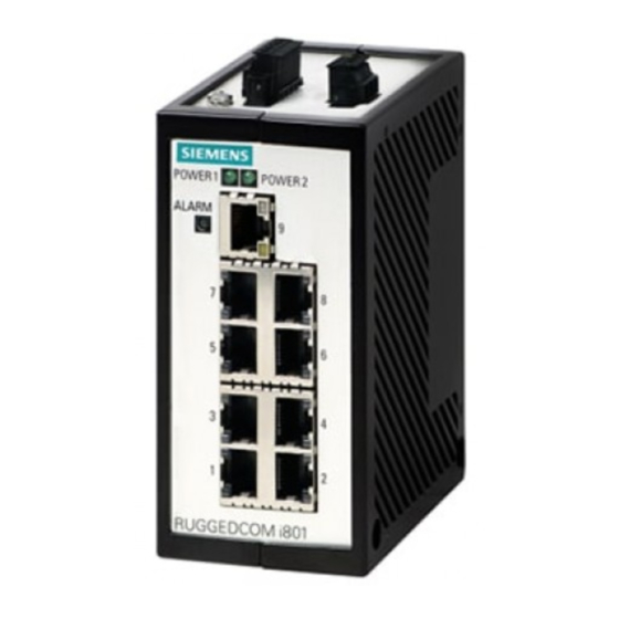
Introduction The RUGGEDCOM i801 is a compact, fully managed Ethernet switch designed to operate reliably in harsh industrial environments. The flexibility of the RUGGEDCOM i801 allows the user to choose from managed or unmanaged, regular or extended temperature, fiber optical or copper interfaces, and fast or Gigabit Ethernet. With up to nine Ethernet ports, the RUGGEDCOM i801 is the perfect choice for a wide variety of demanding industrial environments such as those found in process control applications (oil and gas, petro-chemical, metals and mining, wind farms). -
Page 11: Description
Introduction 1.2 Description • VLAN (802.1Q) to segregate and secure network traffic • RADIUS centralized password management • SNMPv3 authentication and 56-bit encryption Rated for Reliability in Harsh Environments • Immunity to EMI and heavy electrical surges • Hazardous Location Certification: Class I, Division 2 •... -
Page 12: Required Tools And Materials
Introduction 1.3 Required Tools and Materials Access Plate RS-232 Console Port (RJ-45) Figure 1.1 RUGGEDCOM i801 Failsafe Alarm Relay Latches to default state when a power disruption or other alarm condition occurs. For more information, refer to: • "Connecting the Failsafe Alarm Relay (If Equipped) (Page 8)"... -
Page 13: Decommissioning And Disposal
Introduction 1.4 Decommissioning and Disposal Tools/Materials Purpose Phillips screwdriver For mounting the device to a panel. 4 x #8-32 screws For mounting the device to a panel. Decommissioning and Disposal Proper decommissioning and disposal of this device is important to prevent malicious users from obtaining proprietary information and to protect the environment. -
Page 14: Installing The Device
This product contains no user-serviceable parts. Attempted service by unauthorized personnel shall render all warranties null and void. Changes or modifications not expressly approved by Siemens AG could invalidate specifications, test results, and agency approvals, and void the user's authority to operate the equipment. -
Page 15: General Procedure
Visually inspect each item in the package for any physical damage. Verify all items are included. IMPORTANT If any item is missing or damaged, contact Siemens for assistance. Mounting the Device The RUGGEDCOM i801 can be ordered with a DIN rail adapter pre-installed on the back of the chassis. - Page 16 Installing the Device 2.3 Mounting the Device Note For detailed dimensions of the device with the DIN rail adapter installed, refer to "Dimension Drawings (Page 21)". Mounting the Device To mount the device to a DIN rail, do the following: Hook the top teeth of the adapter onto the DIN rail. DIN Rail DIN Rail Adapter Figure 2.1...
-
Page 17: Connecting The Failsafe Alarm Relay (If Equipped)
Installing the Device 2.4 Connecting the Failsafe Alarm Relay (If Equipped) Removing the Device To remove the device from a DIN rail, do the following: Insert a flathead screwdriver into the slot of the sliding release and move it down. DIN Rail DIN Rail Adapter Figure 2.2 Removing the Device from a DIN Rail... -
Page 18: Connecting Power
Installing the Device 2.5 Connecting Power Connecting Power The RUGGEDCOM i801 supports a single low DC power supply with reverse polarity and dual independent inputs. This allows for two redundant DC power sources with the same nominal voltage to be connected. To connect power to the device, do the following: NOTICE •... - Page 19 Installing the Device 2.5 Connecting Power [Optional] If connecting a second redundant power source, repeat Step 1 Step 2, making sure to connect the power supply to the P2 ports. Positive Terminal Negative Terminal GND Terminal Chassis Ground Terminal Figure 2.5 Terminal Block Wiring – Dual DC Power Supply Inputs Connect the chassis ground terminal to protective Earth.
-
Page 20: Device Management
Device Management This section describes how to connect to and manage the device. Connecting to the Device The following describes the various methods for accessing the RUGGEDCOM i801 console and Web interfaces on the device. For more detailed instructions, refer to the RUGGEDCOM ROS Configuration Manual for the RUGGEDCOM i801. -
Page 21: Configuring The Device
Device Management 3.2 Configuring the Device Name Description Comment RJ45 Male DB9 Female Read to Send The DSR, RI and DTR pins are connected together internally. The CTS and RTS pins are connected together internally. Communication Ports Connect any of the available Ethernet ports on the device to a management switch and access the RUGGEDCOM i801 console and Web interfaces via the device's IP address. - Page 22 Device Management 3.3 Inserting/Removing the MicroSD/MicroSDHC Card • Do not expose the microSD/microSDHC card to large magnetic or static electric fields. • Do not bend or drop the microSD/microSDHC card. NOTICE Security hazard – risk of unauthorized access and/or exploitation. Make sure to remove the microSD/microSDHC card before decommissioning the device or sending the device to a third-party.
- Page 23 Device Management 3.3 Inserting/Removing the MicroSD/MicroSDHC Card RUGGEDCOM i801 Installation Manual, 01/2021, C79000-G8976-1003-06...
-
Page 24: Communication Ports
Communication Ports The RUGGEDCOM i801 can be equipped with various types of communication ports to enhance its abilities and performance. To determine which ports are equipped on the device, refer to the factory data file available through RUGGEDCOM i801 . For more information on how to access the factory data file, refer to the RUGGEDCOM ROS Configuration Manual for the RUGGEDCOM i801. - Page 25 Communication Ports 4.1 Copper Ethernet Ports WARNING Electric shock hazard – risk of serious personal injury and/or equipment interference If shielded cables are used, make sure the shielded cables do not form a ground loop via the shield wire and the RJ45 receptacles at either end. Ground loops can cause excessive noise and interference, but more importantly, create a potential shock hazard that can result in serious injury.
-
Page 26: Fiber Optic Ethernet Ports
Communication Ports 4.2 Fiber Optic Ethernet Ports Fiber Optic Ethernet Ports Fiber optic Ethernet ports are available with LC (Lucent Connector) connectors. Make sure the Transmit (Tx) and Receive (Rx) connections of each port are properly connected and matched to establish a proper link. Tx Connector Rx Connector Figure 4.3... - Page 27 Communication Ports 4.2 Fiber Optic Ethernet Ports RUGGEDCOM i801 Installation Manual, 01/2021, C79000-G8976-1003-06...
-
Page 28: Technical Specifications
Technical Specifications This section provides important technical specifications related to the device and available modules. Power Supply Specifications Power Minimum Input Maximum Input Internal Maximum Power Supply Type Fuse Rating Consumption 24 VDC 9 VDC 32 VDC 3A (T) (T) denotes a time-delay fuse. Failsafe Alarm Relay Specifications Note The following specifications are for Class-2 circuits only. -
Page 29: Fiber Optic Ethernet Port Specifications
3 dBm. To convert from peak to average, subtract 3 dBm. • Maximum segment length is greatly dependent on factors such as fiber quality, and the number of patches and splices. Consult a Siemens sales associate when determining maximum segment distances. Fixed Gigabit Transceivers... -
Page 30: Dimension Drawings
Technical Specifications 5.7 Dimension Drawings Dimension Drawings Note All dimensions are in millimeters, unless otherwise stated. 11.7 77.5 95.3 99.5 56.5 Figure 5.1 Overall Dimensions RUGGEDCOM i801 Installation Manual, 01/2021, C79000-G8976-1003-06... - Page 31 Technical Specifications 5.7 Dimension Drawings RUGGEDCOM i801 Installation Manual, 01/2021, C79000-G8976-1003-06...
-
Page 32: Certification
Certification The RUGGEDCOM i801 device has been thoroughly tested to guarantee its conformance with recognized standards and has received approval from recognized regulatory agencies. Approvals This section details the standards to which the RUGGEDCOM i801 complies. 6.1.1 This device meets the requirements of the following Canadian Standards Association (CSA) standards under certificates 2058468 (general safety) and 2068170 (hazardous locations): CAN/CSA-C22.2 No. -
Page 33: 6.1.2 Atex/Iec Ex
• 12-24 VDC, 2A, Class III 6.1.3 European Union (EU) This device is declared by Siemens AG to comply with essential requirements and other relevant provisions of the following EU directives: • EN 61000-6-2 Electromagnetic Compatibility (EMC) – Part 6-2: Generic Standards – Immunity for Industrial Environments •... -
Page 34: Fcc
Methods of Measurement The device is marked with a CE marking and can be used throughout the European community. A copy of the EU Declaration of Conformity is available via Siemens Industry Online Support at https://support.industry.siemens.com/cs/ww/en/view/109475424. 6.1.4 This device has been tested and found to comply with the limits for a Class A digital device, pursuant to Part 15 of the FCC Rules. -
Page 35: 6.1.7 Iso
Support at https://support.industry.siemens.com/cs/ww/en/view/89855782. 6.1.9 RoHS This device is declared by Siemens AG to meet the requirements of the following RoHS (Restriction of Hazardous Substances) directives for the restricted use of certain hazardous substances in electrical and electronic equipment: China RoHS 2 •... -
Page 36: 6.1.10 Other Approvals
Certification 6.1.10 Other Approvals 6.1.10 Other Approvals This device meets the requirements of the following additional standards: • IEC 61000-6-2 Electromagnetic Compatibility (EMC) – Part 6-2: Generic Standards – Immunity for Industrial Environments EMC and Environmental Type Tests The RUGGEDCOM i801 has passed the following EMC and environmental tests. IEC 61850-3 Type Tests Test Description... - Page 37 Certification 6.2 EMC and Environmental Type Tests Description Test Levels Fast Transient Signal ports ± 4 kV @ 5 kHz DC Power ports ± 4 kV @ 5 kHz Earth ground ports ± 4 kV @ 5 kHz Oscillatory Signal ports 2.5 kV common mode @ 1MHz DC Power ports 2.5 kV common, 1 kV differential mode @ 1MHz...
- Page 38 Further Information Siemens RUGGEDCOM https://www.siemens.com/ruggedcom Industry Online Support (service and support) https://support.industry.siemens.com Industry Mall https://mall.industry.siemens.com Siemens AG Digital Industry Process Automation Postfach 48 48 90026 NÜRNBERG GERMANY...
Need help?
Do you have a question about the SIMATIC NET RUGGEDCOM i801 and is the answer not in the manual?
Questions and answers