GORMAN-RUPP PUMPS 80 Series Installation, Operation, And Maintenance Manual With Parts List
Hide thumbs
Also See for 80 Series:

Related Manuals for GORMAN-RUPP PUMPS 80 Series


Summary of Contents for GORMAN-RUPP PUMPS 80 Series
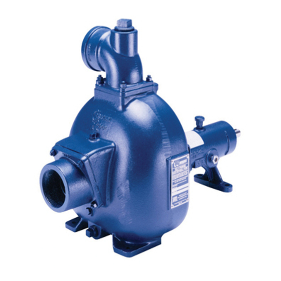
- Page 1 OM-06771-01 October 19, 2015 INSTALLATION, OPERATION, AND MAINTENANCE MANUAL WITH PARTS LIST 80 SERIES PUMP MODEL 82E1-L100W FT4-X GORMAN‐RUPP PUMPS www.grpumps.com 2015 Gorman‐Rupp Pumps Printed in U.S.A.
- Page 2 Register your new Gorman‐Rupp pump online at www.grpumps.com Valid serial number and e‐mail address required. The engine exhaust from this product contains chemicals known to the State of California to cause cancer, birth defects or other reproductive harm. RECORD YOUR PUMP MODEL AND SERIAL NUMBER Please record your pump model and serial number in the spaces provided below.
-
Page 3: Table Of Contents
TABLE OF CONTENTS INTRODUCTION ..........PAGE I - 1 SAFETY - SECTION A . - Page 4 TABLE OF CONTENTS (continued) PUMP MAINTENANCE AND REPAIR - SECTION E ....PAGE E - 1 STANDARD PERFORMANCE CURVE ........PAGE E - 1 PARTS LISTS: Pump Model...
-
Page 5: Introduction
80 SERIES OM-06771 INTRODUCTION Thank You for purchasing a Gorman‐Rupp pump. HAZARD AND INSTRUCTION Read this manual carefully to learn how to safely DEFINITIONS install and operate your pump. Failure to do so could result in personal injury or damage to the The following are used to alert maintenance per... -
Page 6: Safety - Section A
80 SERIES OM-06771 SAFETY - SECTION A This information applies to 80 Series 4. Check the temperature before engine driven pumps. Refer to the opening any covers, plates, or manual accompanying engine plugs. before attempting to begin operation. 5. Close the suction and discharge valves. - Page 7 80 SERIES OM-06771 Do not remove plates, covers, gauges, Fuel used by internal combustion pipe plugs, or fittings from an over engines presents an extreme explosion heated pump. Vapor pressure within the and fire hazard. Make certain that all pump can cause parts being disen...
-
Page 8: Installation - Section B
80 SERIES OM-06771 INSTALLATION - SECTION B Review all SAFETY information in Section A. specific application. Since the pressure supplied to the pump is critical to performance and safety, Since pump installations are seldom identical, this be sure to limit the incoming pressure to 50% of the... -
Page 9: Positioning Pump
OM-06771 80 SERIES d. Check levels and lubricate as necessary. Re Mounting fer to LUBRICATION in the MAINTENANCE Locate the pump in an accessible place as close as AND REPAIR section of this manual and per practical to the liquid being pumped. Level mount... -
Page 10: Gauges
80 SERIES OM-06771 place by tightening the flange bolts and/or cou total area of the openings in the strainer is at least plings. three or four times the cross section of the suction line, and that the openings will not permit passage Lines near the pump must be independently sup... -
Page 11: Discharge Lines
OM-06771 80 SERIES reduce the inlet velocity. Calculate the required NOTE submergence using the following formula based The pipe submergence required may be reduced on the increased opening size (area or diameter). by installing a standard pipe increaser fitting at the end of the suction line. -
Page 12: Grounding
80 SERIES OM-06771 vent clogging, but not so large as to affect pump the clamp or fastener has made a tight electrical discharge capacity. connection with the rod. GROUNDING To eliminate electrostatic build‐up by the liquid be ing pumped, the unit must be grounded by attach... -
Page 13: Operation - Section C
OM-06771 80 SERIES OPERATION - SECTION C Review all SAFETY information in Section A. cated (see LUBRICATION in MAINTENANCE AND REPAIR). Follow the instructions on all tags, labels and This pump is self‐priming, but the pump should decals attached to the pump. -
Page 14: Operation
OM-06771 80 SERIES Be sure the pump unit is properly grounded before line connections and fittings tight to maintain maxi operation. See GROUNDING, Section B. mum pump efficiency. OPERATION Liquid Temperature And Overheating The maximum liquid temperature for this pump is F (71 C). -
Page 15: Pump Vacuum Check
OM-06771 80 SERIES Pump Vacuum Check On engine driven pumps, reduce the throttle speed slowly and allow the engine to idle briefly be fore stopping. NOTE Petroleum products are very sensitive to changes in temperature. Warmer temperatures elevate the product vapor pressure resulting in low vacuum readings. -
Page 16: Troubleshooting - Section D
80 SERIES OM-06771 TROUBLESHOOTING - SECTION D Review all SAFETY information in Section A. Before attempting to open or service the pump: 1. Familiarize yourself with this manu 2. Shut down the engine and take pre cautions to ensure that the pump will remain inoperative. - Page 17 OM-06771 80 SERIES TROUBLE POSSIBLE CAUSE PROBABLE REMEDY PUMP STOPS OR Air leak in suction line. Correct leak. FAILS TO DELIVER Lining of suction hose collapsed. Replace suction hose. RATED FLOW OR PRESSURE Leaking or worn seal or pump gasket.
-
Page 18: Preventive Maintenance
80 SERIES OM-06771 equipped) between regularly scheduled inspec PREVENTIVE MAINTENANCE tions can indicate problems that can be corrected Since pump applications are seldom identical, and before system damage or catastrophic failure oc pump wear is directly affected by such things as curs. -
Page 19: Pump Maintenance And Repair - Section E
80 SERIES OM-06771 PUMP MAINTENANCE AND REPAIR - SECTION E MAINTENANCE AND REPAIR OF THE WEARING PARTS OF THE PUMP WILL MAINTAIN PEAK OPERATING PERFORMANCE. STANDARD PERFORMANCE FOR PUMP MODEL 82E1-L100W FT4-X Based on 70 F (21 C) clear water (corrected to Contact the Gorman‐Rupp Company to verify per... - Page 20 OM-06771 80 SERIES ILLUSTRATION PARTS PAGE Figure 1. Pump Model 82E1-L100W FT4-X PAGE E - 2 MAINTENANCE & REPAIR...
-
Page 21: Parts Lists
80 SERIES OM-06771 PARTS LIST Pump Model 82E1-L100W FT4-X (From S/N 1602839 Up) If your pump serial number is followed by an “N”, your pump is NOT a standard production model. Contact the Gorman‐Rupp Company to verify part numbers. ITEM... - Page 22 OM-06771 80 SERIES ILLUSTRATION Figure 2. 82E1-(L100) PPO PAGE E - 4 MAINTENANCE & REPAIR...
- Page 23 80 SERIES OM-06771 PARTS LIST 82E1-(L100) PPO ITEM PART PART NAME NUMBER PUMP CASING SEE NOTE BELOW IMPELLER 38614-036 13040 SEAL ASSY 25271-888 DISCHARGE STICKER 6588BJ STREET ELBOW RS32 11999 PUMP CASING GSKT SET 229G 20010 INTERMEDIATE BRKT 38264-224 10010...
- Page 24 OM-06771 80 SERIES ITEM PART MAT'L PART NAME NUMBER CODE PUMP CASING 6851D 13040 IMPELLER 38614-036 13040 SEAL ASSY 25271-888 DISCHARGE STICKER 6588BJ STREET ELBOW RS32 11999 PUMP CASING GSKT SET 229G 20010 INTERMEDIATE BRKT 38264-224 10010 STUD C0606 15991...
-
Page 25: Pump And Seal Disassembly And Reassembly
80 SERIES OM-06771 PUMP AND SEAL DISASSEMBLY 4. Check the temperature before opening any covers, plates, or AND REASSEMBLY plugs. 5. Close the suction and discharge Review all SAFETY information in Section A. valves. 6. Vent the pump slowly and cau... -
Page 26: Impeller Removal
OM-06771 80 SERIES (Figure 2) NOTE The stationary seat and O‐ring may also be re Remove the nuts (9) securing the pump casing to moved by disengaging the hardware (12 and 13) the intermediate bracket (7). Separate the pump securing the intermediate to the engine and sliding... - Page 27 80 SERIES OM-06771 age. If any components are worn, replace the com cluded with the seal. It is not used in this applica tion (see Figure 3). plete seal; never mix old and new seal parts. To ease installation of the seal, lubricate the bel...
-
Page 28: Impeller Installation And Adjustment
OM-06771 80 SERIES pipe to press the seat into the intermediate bore un against the wear plate when the shaft is turned. Af til fully seated. The O.D. of the pipe should be ap ter the impeller scrapes, add approximately .008 proximately the same as the O.D. -
Page 29: Lubrication
80 SERIES OM-06771 LUBRICATION ENGINE MODIFICATIONS Seal Assembly The engine used on this pump is not a standard The seal assembly is lubricated by the medium be commercial model. It has been specially modified ing pumped. No additional lubrication is required. - Page 30 For Warranty Information, Please Visit www.grpumps.com/warranty or call: U.S.: 419-755-1280 Canada: 519-631-2870 International: +1-419-755-1352 GORMAN‐RUPP PUMPS...
Need help?
Do you have a question about the 80 Series and is the answer not in the manual?
Questions and answers