Table of Contents
Advertisement
Quick Links
Advertisement
Table of Contents

Related Manuals for WIELANDER+SCHILL IM 240-i


Summary of Contents for WIELANDER+SCHILL IM 240-i
- Page 1 IM 240-i MIG-MAG Welding Inverter Operation Manual REV 1.0 02/2022...
-
Page 2: Table Of Contents
IM 240-i Operation manual CONTENT INTRODUCTION ......................4 SETUP ..........................4 ....................4 ETUP CONDITIONS ..................4 ELECTING THE ACCESSORIES ...................... 5 MIG/MAG TORCH ..................... 6 ORCH WIRE LINER ...................... 7 HE FEEDING UNIT ..................8 ELD AREA PREPARATION ................8 ONNECTING THE PRESSURE BOTTLE ................ - Page 3 Operation manual IM 240-i ....................16 PERATING ANEL ............17 ET UP ADJUSTMENT AND DISPLAY DESCRIPTION CARE AND MAINTENANCE ..................19 ..................19 ISPOSAL OFT THE MACHINE TECHNICAL DATA ...................... 20 AVERAGE CONSUMPTION VALUES FOR WELDING ..........21 ......21...
-
Page 4: Introduction
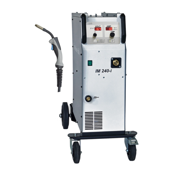
Operation manual before you start. 1.1 Product introduction IM 240-i welding machine is compact MIG-MAG welding inverter especially developed for car body repair. Its excellent brazing characteristic as well as good steel welding possibilities enables to use this device to repair all kinds of vehicles with fine quality results. -
Page 5: Mig/Mag Torch
Operation manual IM 240-i 2.3 Connecting to the electric network Check if the voltage stated on the device label complies with rated voltage of alternate voltage of your electric network. The device can be connected to electric socket equipped with protective contact installed by authorized electrician (TN system according IEC 60364). -
Page 6: Torch Wire Liner
IM 240-i Operation manual 2.5 Torch wire liner For mild steel, the wire feed tube - a liner for welding - consists of a steel spiral. When using wire electrodes made of chromium / nickel steel and of aluminum and other metals, a tube of wear-resistant plastic (for example Teflon) is used. -
Page 7: The Feeding Unit
Operation manual IM 240-i 2.6 The feeding unit Pressure adjustment Feeding rolls Fixing point Please choose the feeding rolls correspond to used welding wire. Material Shape Diameter Article-Number 0,6/0,8mm 337219 Inox 0.8/1.0mm 337220 CuSi CuAl AlMg 0,8/1,0mm AlSi When the feeding wheel is set up, you can see on the front side of the wheel the assigned welding wire diameter (value is in mm). -
Page 8: Weld Area Preparation
IM 240-i Operation manual 2.7 Weld area preparation A work piece must be clean in the welding area, free of paint, metallic coat, dirt, rust, fat and moisture. The preparation of weld must be according to technical instructions for welding. -
Page 9: Safety And Fire Instruction
Operation manual IM 240-i 3 SAFETY AND FIRE INSTRUCTION Keep this device out from children. You have to follow the safety and fire instruction when you work with welding device for welding in protective atmosphere. Regulations for preven- ting of accidents during "welding, cutting and similar working activities". -
Page 10: Handling The Pressure Bottles
IM 240-i Operation manual - Be conscious of possibility of hidden fire on covered objects or in another rooms due tu heat transfer. After finishing of welding check up the welding place for smoking parts or small fires in the time interval up to 6 or 8 hours. -
Page 11: Extraordinary Menace During Welding
Operation manual IM 240-i 3.5 Extraordinary menace during welding - It`s not allowed to weld in rooms with increased “danger” of fire or explosion. The special regulations must be followed in this areas. - It`s not allowed to weld in tanks for gas, fuel, oil, paint etc., even if they are empty for a long time. -
Page 12: Welding Processes
IM 240-i Operation manual 4 WELDING PROCESSES 4.1 MIG/MAG Welding Partial mechanical gas shielded arc welding (MIG), optionally as MIG (inert gas welding, EN ISO 4063: process 131) or MAG welding (metal welding with active, ie reactive gases, EN ISO 4063: process 135), is an arc welding process in which the consumable welding wire is continuously tracked by a variable speed motor. - Page 13 Operation manual IM 240-i Arc ranges for 1.0mm Fe G3Si wire Short Arc The short arc occurs in the lower power range, at lower current intensities and arc voltages. Short arc transfer time The arc length changes cyclically. Thus, working point shifts of welding current and welding voltage are connected.
- Page 14 IM 240-i Operation manual Mixed Arc Mixed arc transfer time view Between the arc types short and spray arc is the mixed arc which is characterized by strong spatter formation. Spray Arc Spray arc transfer time view The spray arc burns continuously without a short-circuit interruption. The material transfer from the wire electrode into the weld pool is fine-droplet.
-
Page 15: Welding Positions
Operation manual IM 240-i 4.2 Welding Positions Seite 15... -
Page 16: Operation
IM 240-i Operation manual 5 Operation 5.1 Turning the device ON Always use the main switch to turn On and Off the device, never use the power plug for this purpose! Power-on sequence After powered special power on sequence is started on the operating panel, to give the user information about the firmware. -
Page 17: Set Up, Adjustment And Display Description
5.3 Set up, adjustment and display description Synergic mode 5.3.1.1 Welding power set up IM 240-i machines can be controlled with full synergic feature. The welding power is to adjust just with one main rotary encoder. By setup of material thickness (in millimeters) are automatically set all welding parameters . - Page 18 IM 240-i Operation manual Manual mode 5.3.2.1 Wire speed setup Set up wire feed speed in m/min by turning the encoder. 5.3.2.2 Welding voltage setup VOLT Set up the welding voltage in Volts by turning the encoder. 5.3.2.3 Arc length correction There is possible to adjust length of the welding arc.
-
Page 19: Care And Maintenance
Operation manual IM 240-i 6 CARE AND MAINTENANCE Pull out the power cable from the socket before every maintenance and troubleshooting. The device is almost maintenance free. It is necessary to check feeding wheel, pressure roller and inflow nozzle regularly, if there is not some dirt. -
Page 20: Technical Data
IM 240-i Operation manual 7 TECHNICAL DATA IM 240-i: Mains connection 1~ 230V +10/-15% 2~200V +15/-5% Mains cable 3x2.5qmm Fusing 16Amp delayed Load capacity 20% @200Amp/24V 60% @140Amp/21V 100% @ 120Amp/20V Peak input current I1p 230V 32Amp @200Amp/24V 200V 37Amp @200Amp/24V... -
Page 21: Average Consumption Values For Welding
Operation manual IM 240-i 8 AVERAGE CONSUMPTION VALUES FOR WELDING 8.1 Average welding wire consumption for MIG / MAG welding Steel welding wire 0,6 mm 0,8 mm 1,0 mm Wire feed rate Welding wire Welding wire Welding wire diameter diameter... -
Page 22: Average Shielding Gas Consumption For Mig / Mag Welding
IM 240-i Operation manual CuSi welding wire 0,6 mm 0,8 mm 1,0 mm Wire feed rate Welding wire Welding wire Welding wire diameter diameter diameter 2m/min 0,5kg/h 0,6kg/h 0,8kg/h 3m/min 0,7kg/h 1kg/h 1,2kg/h 5m/min 1,2kg/h 1,6kg/h 2kg/h 7m/min 1,7kg/h 2,2kg/h... -
Page 23: Troubleshooting
Operation manual IM 240-i 9 TROUBLESHOOTING Mechanical defects are mostly the result of irregular wire feeding or its blocking. Electrical defects cause partial or full device failure. Only an authorized electrician can repair the electrical part of welding device. The troubleshooting should be executed in the OFF mode first and in the following sequence: - Check up the solidity of electrical connections on switches, current transformer, suppressor and also the solidity of plugged and soldered connections. - Page 24 IM 240-i Operation manual Engine malfunction take the device to service Wire feeding malfunction Pressing roller is loosen Increase the pressure to the leaf spring by using the grooved screw Wire has got out from feeding Center the intake nozzle...
-
Page 25: Distributors Worldwide
Operation manual IM 240-i 10 Distributors Worldwide Here you can find our worldwide distributors: https://www.wielanderschill.com/service/vertretungen-weltweit/ https://www.wielanderschill.com/en/service/distributors-worldwide/ Seite 25... -
Page 26: Eu- Declaration Of Conformity
IM 240-i Operation manual 11 EU- Declaration of Conformity Seite 26... - Page 27 Operation manual IM 240-i Seite 27...
- Page 28 IM 240-i Operation manual Seite 28...
Need help?
Do you have a question about the IM 240-i and is the answer not in the manual?
Questions and answers