
Related Manuals for WIELANDER+SCHILL Inverta Puls IP6-2 ACT


Summary of Contents for WIELANDER+SCHILL Inverta Puls IP6-2 ACT
- Page 1 Operation manual Inverta Puls IP6-2 ACT Operation manual Inverta Puls IP6 – 2 ACT May 2013 REV 2.0 Page 1 of 20...
-
Page 2: Table Of Contents
Inverta Puls IP6-2 ACT Operation manual CONTENT PREFACE ........................4 ................... 4 RODUCT INTRODUCTION ..................4 SSEMBLY REQUIREMENTS ..................4 ELECTING THE ACCESSORIES PUTTING INTO OPERATION ..................5 ..............5 ONNECTING TO THE ELECTRIC NETWORK MIG/MAG ................5 ONNECTING THE TORCH ................. - Page 3 Operation manual Inverta Puls IP6-2 ACT TECHNICAL DATA ...................... 18 TROUBLESHOOTING ....................19 Page 3 of 20...
-
Page 4: Preface
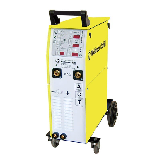
Inverta Puls IP6-2 ACT Operation manual 1 PREFACE Dear customer! Congratulation to purchasing of this quality inverter welding machine. Please read whole Operation manual before you start. 1.1 Product introduction Inevrta Puls IP6 -2 welding machine is compact pulse MIG-MAG welding inverter especially developed for car body repair. -
Page 5: Putting Into Operation
Operation manual Inverta Puls IP6-2 ACT 2 PUTTING INTO OPERATION 2.1 Connecting to the electric network Check if the voltage stated on the device label complies with rated voltage of alternate volta- ge of your electric network. The device can be connected to electric socket equipped with protective contact installed by authorized electrician. -
Page 6: Selecting The Feeding Wheel
Inverta Puls IP6-2 ACT Operation manual Never use damaged torch! Make sure the contact tip match the manufacturer’s recommendations for type and diameter of used wire. Connect the welding conduction main connecting plug into the main socket on the front side. Secure it with the lock nut. -
Page 7: Connecting The Return Cable
Operation manual Inverta Puls IP6-2 ACT bottle. Connect a hose to the MIG-MAG welding device reduction valve. The recommended gas flow is 8 – 15 liter/minute in a room without draft. If you use an adjustable reduction valve, you can adjust a gas flow with a wing nut with a liter scale. -
Page 8: Safety And Fire Instruction
Inverta Puls IP6-2 ACT Operation manual SAFETY AND FIRE INSTRUCTION Keep this device out from children. You have to follow the safety and fire instruction when you work with welding device for welding in protective atmosphere. Regulations for preven- ting of accidents during "welding, cutting and similar working activities". -
Page 9: Handling The Pressure Bottles
Operation manual Inverta Puls IP6-2 ACT 3.3 Handling the pressure bottles You have to follow respective safety regulations (technical regulations for pressure gas TRG 253 and 303). Due to high presure inside the bottles (up to 200 bar) it is necessary to secure them against mechanical damage, overturning, downfall, heating up (max 50°C), against sunshine expo-... -
Page 10: Operation
Inverta Puls IP6-2 ACT Operation manual 4 Operation 4.1 Turning the device ON Always use the main switch on the back side of the machine to turn On and Off the device, never use the power plug for this purpose! 4.1.1 Power-on sequence... -
Page 11: Manual Wire Inching & Gas Testing
Operation manual Inverta Puls IP6-2 ACT 4.2.1 Manual wire inching & Gas testing (Not available if MMA/TIG selected) Manual wire inch mode is activated by pressing the Mode button for 2sec. In wire speed window is possible to adjust the speed for manual feed. -
Page 12: Set Up, Adjustment And Display Description
Inverta Puls IP6-2 ACT Operation manual 4.3 Set up, adjustment and display description 4.3.1 Material thickness window To have an advance of synergy functionality must be welding power set by setting up the material thickness. Pre-programmed synergy tables are supposed for flat butt weld. -
Page 13: Job Mode
Operation manual Inverta Puls IP6-2 ACT 4.4 JOB Mode Press both buttons simultaneously to enter to the job mode After entered to the Job mode, actual job number is shown in the Material thickness window - as example J1. There is 10 jobs available: J0 – J9. By pressing the Up/Down keys in Material thickness window You can choose wanted job. -
Page 14: Menu
Inverta Puls IP6-2 ACT Operation manual 4.5 MENU For enhanced adjustment is available MENU function. Press both buttons simultaneously to enter to the MENU 4.5.1 List of MENU parameters Double Par. Displayed Pulse Pulse Name Description Min. Max. Step Unit... -
Page 15: Selecting The Active Feeder
Operation manual Inverta Puls IP6-2 ACT 4.6 Selecting the active feeder Active feed unit selection is indicated by LED indicator above the corresponding euro torch connector. To switch the idle feed unit on, must be just pressed the trigger button on the corresponding torch. -
Page 16: No Arc Timeout
Inverta Puls IP6-2 ACT Operation manual Hot start level Welding Crater fill level TRIGGER 4-TACT MIG/MAG operation 4.9 NO ARC timeout If there is no arc detected for more than 3 seconds during active welding the inverter will be automatically switched off. -
Page 17: Care And Maintenance
Operation manual Inverta Puls IP6-2 ACT 5 CARE AND MAINTENANCE Pull out the power cable from the socket before every maintenance and troubleshooting. The device is almost maintenancefree. It is necessary to check feeding wheel, pressure roller and inflow nozzle regularly, if there is not some dirt. -
Page 18: Technical Data
Inverta Puls IP6-2 ACT Operation manual 6 TECHNICAL DATA Inverta Pulse IP6: Mains connection 3~ 400V +/-10% Mains cable 4x2.5qmm Fusing 16Amp delayed Load capacity 40% @270Amp/27.5V 60% @240Amp/26V 100% @ 180Amp/23V Peak input current I1p 19Amp @270Amp/30.8V Effective maximum input current I1eff... -
Page 19: Troubleshooting
Operation manual Inverta Puls IP6-2 ACT 7 TROUBLESHOOTING Mechanical defects are mostly the result of irregular wire feeding or its blocking. Electrical defects cause partial or full device failure. Only an authorized electrician can repair the electrical part of welding device. - Page 20 Inverta Puls IP6-2 ACT Operation manual Wire feeding malfunction 1. Pressing roller is loosen Increase the pressure to the leaf spring by using the grooved screw 2. Wire has got out from feeding Center the intake nozzle 3. Wire feed wheel grove is worn up Change the wire feed wheel 4.
Need help?
Do you have a question about the Inverta Puls IP6-2 ACT and is the answer not in the manual?
Questions and answers