Table of Contents
Advertisement
Quick Links
MV Marketing und Vertriebs-GmbH & Co. KG
Professionelle Karosserie-Spezialwerkzeuge
A very straight forward and
simple settings
- it will tolerate very hard impacts.
welding (
•MIG/MAG
with
•4 roller drive
trim adjustment
•Use with D300 wire spool
•Display with hold function for
welding current and tension.
•Dynamic pulse adjustment to remove
the „ball" at the end of the wire
•
Extremely good welding results even on very thin sheet
metal. There are no problems with steelwelding on panels
as thin as 0,6mm (0,023 in)
Siederstr. 50 D-78054 Villingen-Schwenningen Tel. +49 (0) 7720 8317 0 E-mail info@wielanderschill.com
because of the
MIG-flux-cored welding wire brazing)
(max. 17 kg)
Content of delivery
Welder with rollers
Torch MB 15, 3m
Earth cable 4 m
Item N
341290
o
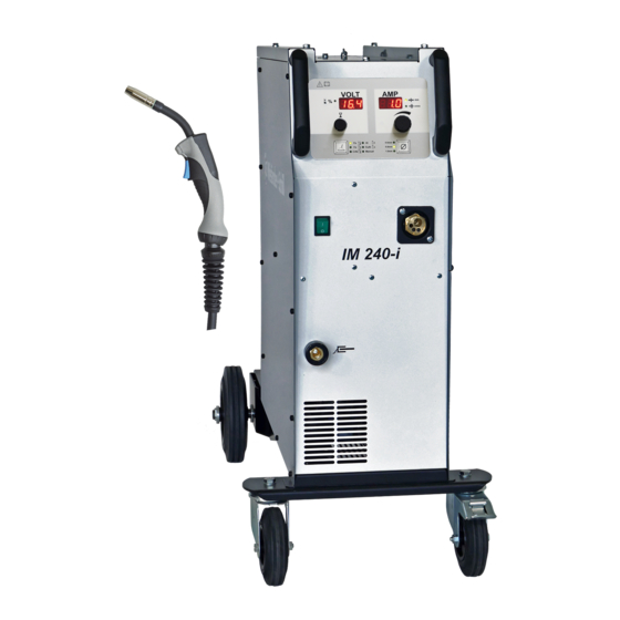
MIG/MAG
welder with inverter technology
simple to use
tough construction
Technical Data
Mains connection
Load capacity (delayed)
Current adjustment range
Voltage adustment range
Welding range/steps
No load output voltage Uo @40°C
Load capacity 60% ED@40°C
Load capacity 100% ED@40°C
Weight
Dimensions (HxBxL)
IM 240-i
machine with
220/240V - 50/60 Hz
16 A
20 - 200A
10 - 35V
continuous
20%/200A/24V
140A / 21V
120A / 20V
35 kg
890x365x600 mm
Advertisement
Table of Contents

Related Manuals for WIELANDER+SCHILL IM 240-i


Summary of Contents for WIELANDER+SCHILL IM 240-i
- Page 1 MIG/MAG IM 240-i MV Marketing und Vertriebs-GmbH & Co. KG welder with inverter technology Professionelle Karosserie-Spezialwerkzeuge simple to use A very straight forward and machine with simple settings tough construction because of the - it will tolerate very hard impacts.
- Page 2 IM 240 I - steel wire 0,6 mm Upgrade Software • New software PD board • Version EC200_14.hex • Open lid at the left side of the welder casing. Transport wheels 0,6 mm Wheel pressure +/- 2,5 Torch with Teflon liner blue inner diam.
- Page 3 PERFEKT welding performance IM 240 I with welding wire SG 2 0,6 mm / gas 80/20 / nozzle 0,6 mm...
- Page 4 Operation manual IM 240-i Operation manual IM 240-i August 2014 REV 2.1 Page 1 of 15...
-
Page 5: Table Of Contents
IM 240-i Operation manual CONTENT PREFACE ........................4 ................... 4 RODUCT INTRODUCTION ..................4 SSEMBLY REQUIREMENTS PUTTING INTO OPERATION ..................5 ..............5 ONNECTING TO THE ELECTRIC NETWORK ......5 ONNECTING THE PRESSURE BOTTLE CONTAINING PROTECTIVE GAS ................5 ONNECTING THE RETURN CABLE MIG/MAG ..................... - Page 6 Operation manual IM 240-i EG-Konformitätserklärung Hersteller / Bevollmächtigter: MAHE Gerätebau GmbH Auwiese 12 D-57223 Kreuztal-Kredenbach Bevollmächtigte Person, Ing. Jaroslav Kučera für die Zusammenstellung der technischen Štefánikova 1 Unterlagen: 059 21 Svit SLOVAKIA Produkt: IM 240-i Hiermit erklären wir, dass die oben beschriebene Maschine allen einschlägigen Bestimmungen der Maschinenrichtlinie 2006/42/EG entspricht.
-
Page 7: Preface
Operation manual before you start. 1.1 Product introduction IM 240-i welding machine is compact MIG-MAG welding inverter especially developed for car body repair. Its excellent brazing characteristic as well as good steel welding possibilities enables to use this device to repair all kinds of vehicles with fine quality results. -
Page 8: Putting Into Operation
Operation manual IM 240-i 2 PUTTING INTO OPERATION 2.1 Connecting to the electric network Check if the voltage stated on the device label complies with rated voltage of alternate volta- ge of your electric network. The device can be connected to electric socket equipped with protective contact installed by authorized electrician (TN system according IEC 60364). -
Page 9: Mig/Mag Torch
IM 240-i Operation manual 2.4 MIG/MAG torch For torch connecting is used EURO Standard torch connector. Please, tighten the connector well to eliminate the conduction losses. A loose connection can cause damage of the machine and torch. Never use damaged torch! Make sure the contact tip match the manufacturer’s recommendations for type and diameter... -
Page 10: Weld Area Preparation
Operation manual IM 240-i 2.6 Weld area preparation A work piece must be clean in the welding area, free of paint, metallic coat, dirt, rust, fat and moisture. The preparation of weld must be according to technical instructions for welding. -
Page 11: Handling The Pressure Bottles
IM 240-i Operation manual - Be conscious of possibility of hidden fire on covered objects or in another rooms due tu heat transfer. After finishing of welding check up the welding place for smoking parts or small fires in the time interval up to 6 or 8 hours. -
Page 12: Operation
Operation manual IM 240-i 4 Operation 4.1 Turning the device ON Always use the main switch to turn On and Off the device, never use the power plug for this purpose! 4.1.1 Power-on sequence After powered special power on sequence is started on the operating panel, to give the user information about the firmware. -
Page 13: Filler Wire Diameter Selection
4.3 Set up, adjustment and display description 4.3.1 Synergic mode 4.3.1.1 Welding power set up IM 240-i machines can be controlled with full synergic feature. The welding power is to adjust just with one main rotary encoder. By setup of material thickness (in millimeters) are automatically set all welding parameters . -
Page 14: Manual Mode
Operation manual IM 240-i 4.3.2 Manual mode 4.3.2.1 Wire speed setup Set up wire feed speed in m/min by turning the encoder. 4.3.2.2 Welding voltage setup VOLT Set up the welding voltage in Volts by turning the encoder. 4.3.2.3 Arc length correction There is possible to adjust length of the welding arc. -
Page 15: Care And Maintenance
IM 240-i Operation manual 5 CARE AND MAINTENANCE Pull out the power cable from the socket before every maintenance and troubleshooting. The device is almost maintenancefree. It is necessary to check feeding wheel, pressure roller and inflow nozzle regularly, if there is not some dirt. -
Page 16: Technical Data
Operation manual IM 240-i 6 TECHNICAL DATA Mains connection 1~ 230V +10/-15% Mains cable 3x2.5qmm Fusing 16Amp delayed Load capacity 20% @200Amp/24V 60% @140Amp/21V 100% @ 120Amp/20V Peak input current I1p 32Amp @200Amp/24V Effective maximum input current I1eff 15Amp @200Amp/24V/20% No load output voltage Uo 40.2... -
Page 17: Troubleshooting
IM 240-i Operation manual 7 TROUBLESHOOTING Mechanical defects are mostly the result of irregular wire feeding or its blocking. Electrical defects cause partial or full device failure. Only an authorized electrician can repair the electrical part of welding device. The trobleshooting should be executed in the OFF mode first and in the following sequence: - Check up the solidity of electrical connections on switches, current transformer, suppressor and also the solidity of plugged and soldered connections. - Page 18 Operation manual IM 240-i Wire feeding malfunction 1. Pressing roller is loosen Increase the pressure to the leaf spring by using the grooved screw 2. Wire has got out from feeding Center the intake nozzle 3. Wire feed wheel grove is worn up Change the wire feed wheel 4.
- Page 19 ä ä ä MIG-Brazing is a kind of soldering technique using: a welding arc together with a special area protection gas. push position protection gas gas nozzle Argon 4.5 preheat and Current nozzle + MIG Brazing wire evaporations of the zinc in front What kind of material you can braze? All kind of steel plates, either coated or uncoated, such as zinc ~, phosphate ~ or aluminium coat.
- Page 20 ä ä ä The differences between MIG-Brazing and steel welding Using the MIG-Brazing the base material never gets into liquid conditions different to welding with steel wire and Mixgas or CO gas. Mixgas = Argon/CO 80/20, 82/18, 85/15 % = soft, no sparks, little root, especially for thin sheet metal gas = 100% = very hot, sparks, deep root, preferred for thick steel liquid braze liquid welding wire...
- Page 21 ä ä ä MIG Brazing – butt weld position sheet metal at car new replacing sheet metal plugs jump from plug to plug if no plugs the sheet to avoid overheating metals tend to squeeze so no penetration Sometimes it might be necessary to re-cut the gap in between the gaps with a thin disc grinder How large should be the gap? How far should be the plugs gap 0,8-1,0mm up to t ≤...
- Page 22 ä ä ä MIG-Brazing – plug holes + longitudinal holes d=5x√ t d=6x√ t d=(5x√ t) x 14 Instruction: Instructions: Instruction: torch in neutral position. torch in push position. torch in neutral position, Start from the outside at 9 Start at the ouside, swing in thin sheet metal.
Need help?
Do you have a question about the IM 240-i and is the answer not in the manual?
Questions and answers