Advertisement
Quick Links
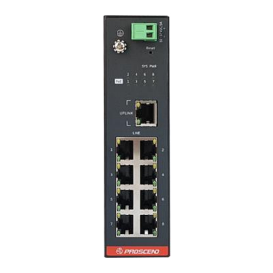
708EPI-DC 8-Port PoE Long Reach
Switch / Extender
Quick Installation Guide
Overview
The 708EPI-DC PoE Switch / Extender features 8 pairs of Long Reach
Ethernet connections in cooperation with the 101EPI. Each pair carries
Ethernet traffic and power over an Ethernet cable up to 800 meters. The
708EPI-DC is designed to locate at network side where the 101EPI is
located at the remote side.
LED Indicators
Each LED indicator on the front panel is described in the following table.
LED
Color
PWR
Green
SYS
Green
PoE1~8
Green
Green
UPLINK
Yellow
Green
LINE 1~8
Yellow
LINE Port Pin Assignment
8-pin RJ45
The LINE interfaces of the 708EPI-DC are standard 8-pin
RJ45 connectors. The following tables display the pinouts.
1
8
MDI Port Pinouts
Pin
Description
1
TX+
2
TX-
3
RX+
4
Not used
5
Not used
6
RX-
7
Not used
8
Not used
Proscend Communications Inc. All rights reserved.
LED
Description
On
Device Power On.
Off
Device Power Off.
On
System is working.
Off
System is off.
Blinking
Device Error.
On
Powered Device Connected.
Off
Powered Device Disconnected.
On
1000Mbps UPLINK LINK UP.
Off
1000Mbps UPLINK LINK DOWN.
Blinking
1000Mbps Data Transmitting.
On
100/10Mbps UPLINK LINK UP.
Off
100/10Mbps UPLINK LINK DOWN.
Blinking
100/10Mbps Data Transmitting.
On
100Mbps LINE LINK UP.
Off
LINE LINK DOWN.
Blinking
100Mbps Data Transmitting.
On
10Mbps LINE LINK UP.
Off
LINE LINK DOWN.
Blinking
10Mbps Data Transmitting.
MDI-X Port Pinouts
Pin
Description
1
RX+
2
RX-
3
TX+
4
Not used
5
Not used
6
TX-
7
Not used
8
Not used
The PoE pinouts of the LINE interfaces are as below when 8 wires are
connected.
Version: 1.00
Pin
1
2
3
4
The PoE pinouts of the LINE interfaces are as below when 4 wires are
connected.
Pin
1
2
3
4
Connecting the Power Supply
▪The power input interface is the 2-pin terminal block (+, -) on the front
panel and is provided the power input voltage 55 ~ 57 VDC/5A from the
power supply.
▪Insert the positive and negative wires into V+ and V- contact on the
terminal block and tighten the wire-clamp screws to prevent the wires
from being loosened.
Ground Connection
To prevent the effects of noise from electromagnetic interference (EMI), run
the ground connection from the ground screw to the grounding surface
before connecting the devices.
Reset Button
Reset button allows you to reboot the unit or restore to factory default
setting.
Reboot
Restore to factory default setting
- 1 -
PoE Pinouts
Description
Pin
V+
5
V+
6
V-
7
V+
8
PoE Pinouts
Description
Pin
V+
5
V+
6
V-
7
Not used
8
Function
Press the button for 1 second
Press the button for more than 5 seconds
Description
V+
V-
V-
V-
Description
Not used
V-
Not used
Not used
Operation
www.proscend.com
Advertisement

Related Manuals for Proscend 708EPI-DC


Summary of Contents for Proscend 708EPI-DC
- Page 1 Overview Description Description The 708EPI-DC PoE Switch / Extender features 8 pairs of Long Reach Ethernet connections in cooperation with the 101EPI. Each pair carries Ethernet traffic and power over an Ethernet cable up to 800 meters. The 708EPI-DC is designed to locate at network side where the 101EPI is located at the remote side.
- Page 2 NOTE: These screws are not included in the package. The head of each screw is less than 7 mm in diameter, the shaft is less than 3 mm in diameter, and the length is less than 10 mm in diameter. P/N:604040000070 - 2 - Proscend Communications Inc. All rights reserved. www.proscend.com...
Need help?
Do you have a question about the 708EPI-DC and is the answer not in the manual?
Questions and answers