Advertisement
Quick Links
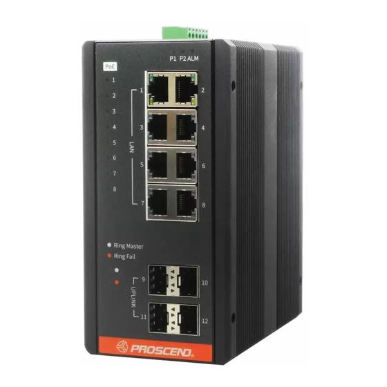
850G Series Industrial Ethernet Switch
Quick Installation Guide
Connecting Power
The 850G Series Industrial Ethernet Switch can be powered from two
power supplies (input range 12 ~ 58 VDC for non-PoE Series, 54 ~ 58 VDC
for PoE Series). Two power supplies are on the top panel of the switch.
Insert the positive and negative wires (AWG 14-26) into V+ and V- contacts
on the terminal block respectively and tighten the wire-clamp screws to
prevent the wires from being loosened.
▪Non-PoE Series
First Power Supply
▪PoE Series
Second Power Supply
WARNING
The DC power should be connected to a well-fused power supply.
Alarm Relay and Ground
▪The alarm relay output contacts are in the middle of the DC terminal
block connector as shown in the figure below.
▪The alarm relay out is "Normal Open", and it will be closed when it is
detecting any predefined failure such as power failures or Ethernet link
failures.
▪The relay output with current carrying capacity of 0.5A @ 24 VDC.
▪The switch must be properly grounded for optimum system performance.
External Power system
Proscend Communications Inc. All rights reserved.
Version: 1.00
Second Power Supply
First Power Supply
Alarm system
Ground Connector
LED Indicators
LED
Color
On: Green
P1/P2
Off
On: Red
ALM (Alarm)
Off
On: Green
RJ45 LAN port
Blinking: Green
Link/Act
Off
On: Yellow
RJ45 LAN port
Speed
Off
On: Green
SFP Uplink port
Link/Act
Off
On: Yellow
SFP Uplink port
Speed
Off
PoE Series only
On: Green
Ring Master
Off
On: Green
Ring Fail
Off
On: Yellow
PoE
Off
RJ45 Connector Pinouts
The pin assignment of RJ45 connector is shown in the following table.
Pin
8-pin RJ45
1,2
1
8
3,6
4,5
7,8
Console Connection
The console port on the top panel is for local management by using a
terminal emulator or a computer with terminal emulation software.
▪DB9 connector connect to computer COM port
▪Baud rate: 115200bps
▪8 data bits, 1 stop bit
▪None Priority
▪None flow control
To connect the host PC to the console port, a RJ45 (male)
connector-to-RS232 DB9 (female) connector cable is used (not included in
package). The RJ45 connector of the cable is connected to the console port
of the switch; the DB9 connector of the cable is connected to the PC COM
port. The pin assignment of the console cable is shown below:
1
6
2
RD
7
3
TD
8
4
9
5
DGND
- 1 -
Description
P1/P2 power line connected or power supplied
P1/P2 power line disconnected or no power supplied
Ethernet link failure or power failure
No Ethernet link failure and no power failure
Ethernet LINK UP
Ethernet traffic detected
Ethernet LINK DOWN
Ethernet LINK UP at 1000Mbps
Ethernet LINK DOWN or LINK UP at 10Mbps/100Mbps
Ethernet LINK UP
Ethernet LINK DOWN
Ethernet LINK UP at 1000Mbps
Ethernet LINK DOWN or LINK UP at 100Mbps
Ring Master enabled
Ring Slave enabled
Ring failure detected
No Ring failure detected
PoE PD (Powered Device) connected
PoE PD (Powered Device) disconnected
Description
PoE Pinouts (PoE models only)
T/Rx+,T/Rx-
V+
T/Rx+,T/Rx-
V-
T/Rx+,T/Rx-
T/Rx+,T/Rx-
1
2
3 (RD)
4
(TD)
5
6
(DGND)
7
8
www.proscend.com
X
X
Advertisement

Related Manuals for Proscend 850G Series


Summary of Contents for Proscend 850G Series
- Page 1 P1/P2 power line connected or power supplied Connecting Power P1/P2 P1/P2 power line disconnected or no power supplied The 850G Series Industrial Ethernet Switch can be powered from two On: Red Ethernet link failure or power failure ALM (Alarm) power supplies (input range 12 ~ 58 VDC for non-PoE Series, 54 ~ 58 VDC No Ethernet link failure and no power failure for PoE Series).
- Page 2 NOTE: For all switches (Non-PoE Series, PoE Series), the operation of wall mounting is the same. M4 Screw Web Interface: Connect & Login 1. Factory default IP: 192.0.2.1 2. Login with default account and password. Username: admin Password: (none) P/N:604040000065 - 2 - Proscend Communications Inc. All rights reserved. www.proscend.com...
Need help?
Do you have a question about the 850G Series and is the answer not in the manual?
Questions and answers