Advertisement
Quick Links
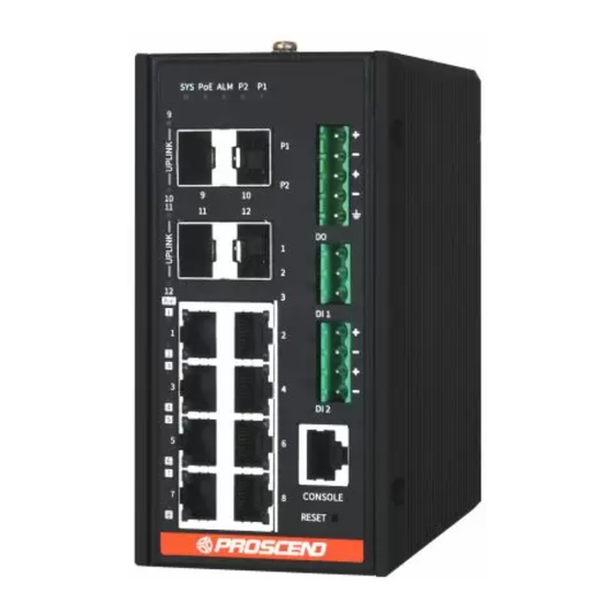
850G-12I & 850G-12PI
Industrial Ethernet Switch
Quick Installation Guide
Connecting Power
_
_
The 850G 12 ports Series Industrial Ethernet Switch can be powered
from two power supplies (input range 12~57 VDC for non-PoE Series, 57
VDC for PoE Series). Two power supplies are in front of the switch.
Insert the positive and negative wires (AWG 20-28) into V+ and V-
contacts on the terminal block respectively and use a flat-head
screwdriver to push in and open the wire clamp.
The DC power should be connected to a well-fused power supply.
_Connecting I/O Ports
_
There are four terminals on the terminal block for digital inputs.
There are three terminals on the terminal block for digital output.
NOTE:
DO configuration (Open/Short) can be reversed (Short/Open) from the UI.
_
_
Reset Button
Function
Reset
Reset to default
setting
_
_
Ground Connector
The switch must be properly grounded for optimum system performance.
Version: 2.00
Pin
Digital Input
DI 1 +
High (+13V to +30V) for "Off"
DI 1 -
DI 2 +
Low (-30 to +3V) for "On"
DI 2 -
DO
Factory default
PIN 1
Open
PIN 2
PIN 2
Short
PIN 3
Operation
Press the button for 3second.
Press the button for more than 6 seconds.
LED Indicators
_
_
The following table explains the LED indicators on the front panel.
LED
Color
On: Green
Power on.
P1
Off
Power off.
On: Green
Power on.
P2
Off
Power off.
On: Red
One of the two powers is abnormal
ALM
Off
The system is operating normally.
On: Green
Over PoE max power budget.
* PoE
Off
Below PoE max power budget.
On: Green
System is ready.
SYS
Blinking
System is booting up.
Off
No power
On: Green
Ethernet LINK UP at 1000Mbps.
1~8
On: Amber
Ethernet LINK UP at 10/100Mbps.
LAN Port
Blinking
Ethernet traffic detected.
Link/Act
Off
Ethernet LINK DOWN.
On: Green
PoE PD (Powered Device) connected.
*
Off
PoE PD (Powered Device) disconnected.
On: Green
LINK UP at 100/1000Mbps.
9~12
SFP Port
Blinking
Traffic detected.
UPLINK
Off
LINK DOWN.
NOTE:
" * " Applicable for PoE Switch edition only.
Console Connection
_
_
The console port on the front panel is for local management by using a
terminal emulator or a computer with terminal emulation software.
DB9 connector connect to computer COM port
Baud rate: 115200bps
8 data bits, 1 stop bit
None Priority
None flow control
To connect the host PC to the console port, a RJ45 (male)
connector-to-RS232 DB9 (female) connector cable is used. The RJ45
connector of the cable is connected to the console port of the switch,
the DB9 connector of the cable is connected to the PC COM port. The pin
assignment of the console cable is shown below:
NOTE:
The console cable is not included in the package.
Description
P/N: 604040000097
Advertisement

Related Manuals for Proscend 850G-12I


Summary of Contents for Proscend 850G-12I
- Page 1 LED Indicators 850G-12I & 850G-12PI Industrial Ethernet Switch The following table explains the LED indicators on the front panel. Quick Installation Guide Color Description Version: 2.00 On: Green Power on. Connecting Power Power off. On: Green Power on. The 850G 12 ports Series Industrial Ethernet Switch can be powered Power off.
- Page 2 NOTE Please scan below QR Code to download online resources. Download link: https://www.proscend.com/en/product/850G-12I.html https://www.proscend.com/en/product/850G-12PI.html NOTE: The type of screw is flat head M3 x 6mm. STEP 2: Hook the unit onto the DIN-rail. STEP 3: Push the bottom of the unit towards the DIN-rail until it locks in place.
Need help?
Do you have a question about the 850G-12I and is the answer not in the manual?
Questions and answers