
Related Manuals for National Instruments Quanser QNET 2.0


Summary of Contents for National Instruments Quanser QNET 2.0
- Page 1 USER MANUAL QNET 2.0 Rotary Pendulum Board for NI ELVIS Set Up and Configuration CAPTIVATE. MoTIVATE. GRAdUATE.
- Page 2 © 2014 Quanser Inc., All rights reserved. Quanser Inc. 119 Spy Court Markham, Ontario L3R 5H6, Canada info@quanser.com Phone: 1-905-940-3575 Fax: 1-905-940-3576 For more information on the solutions Quanser Inc. offers, please visit the web site at: http://www.quanser.com This document and the software described in it are provided subject to a license agreement. Neither the software nor this document may be used or copied except as specified under the terms of that license agreement.
-
Page 3: Table Of Contents
Contents Safety Information Introduction System Hardware System Schematic Hardware Components Environmental System Parameters QNET Rotary Pendulum Assembly Instructions QNET Rotary Pendulum and NI ELVIS II Setup QNET Rotary Pendulum Components NI ELVIS II Components NI ELVIS II Setup Procedure Troubleshooting General Software Issues General Hardware Issues QNET Rotary Pendulum Issues... - Page 4 Safety Information The following symbols and definitions are interchangeably used throughout the User Manual: Symbol Description Caution: consult documenation for additional information Direct Current On (Power) [on NI ELVIS II unit] ⃝ Off (Power) [on NI ELVIS II unit] Table 0.1: Symbols QNET ROTARY PENDULUM - User Manual...
-
Page 5: Introduction
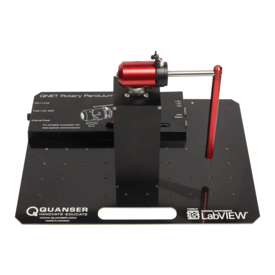
1 Introduction The Quanser QNET 2.0 Rotary Inverted Pendulum Board for NI ELVIS II, pictured in Figure 1.1, is a versatile servo system designed to teach and demonstrate a variety of inverted pendulum based experiments. The system is driven using a direct-drive 18 V brushed DC motor housed in a solid aluminum frame. Single-ended rotary encoders are used to measure the angular positon of the DC motor and the pendulum. -
Page 6: System Hardware
2 System Hardware 2.1 System Schematic The QNET Rotary Pendulum provides an integrated amplifier and a communication interface with the NI ELVIS II for the amplifier command and encoder ports. The interaction between the different system components on the QNET Rotary Pendulum is illustrated in Figure 2.1. The NI ELVIS II is interfaced to the PC or laptop via USB link in the QNET Rotary Pendulum Interface. - Page 7 Description Description Motor metal chamber 8-pin Motor power connector Pendulum Link 5-pin Encoder connector +5 V, 15 V, +15 V LEDs 5-pin Encoder connector User and Status LEDs High-resolution encoder 24 V QNET power jack Pendulum pivot Fuse DC Motor External Power indicator LED High-resolution encoder PCI Connector...
- Page 8 Figure 2.4: Quanser QNET 2.0 Rotary Inverted Pendulum Board for NI ELVIS II components 2.2.1 DC Motor The QNET Rotary Pendulum includes a direct-drive 18 V brushed DC motor housed in a solid aluminum frame. The motor specifications are given in Table 2.3.
-
Page 9: Environmental
2.2.4 Status LED The QNET Rotary Pendulum is fitted with a variety of safety measures that use the Status LED for feedback, see Figure 2.3. In particular, two digital enable lines (one high, one low) are used to ensure proper system configuration. The system states are displayed as in Table 2.2. - Page 10 Symbol Description Value DC Motor 18.0 V Nominal input voltage 22.0 mNm Nominal torque τ 3050 RPM Nominal speed ω 0.540 A Nominal current Terminal resistance 0.042 Nm/A Torque constant 0.042 V/(rad/s) Motor back-emf constant 4.0 × 10 Rotor inertia 1.16 mH Rotor inductance 0.016 kg...
-
Page 11: Qnet Rotary Pendulum Assembly Instructions
3 QNET Rotary Pendulum Assembly Instructions Follow the instructions below to setup the QNET Rotary Pendulum: 1. Remove the four thumbscrews that are used to attach the Rotary Pendulum base to the QNET board for transport. 2. Bring the pendulum assembly upright, and align the screw holes in the bottom of the base with the holes indicated on the bottom surface of the QNET board. -
Page 12: Qnet Rotary Pendulum And Ni Elvis Ii Setup
4 QNET Rotary Pendulum and NI ELVIS II Setup The procedure to install a QNET Rotary Pendulum module on the NI ELVIS II is detailed in this section. The NI ELVIS II components used in the installation procedure are located and marked by an ID number in Figure 4.1, and described in Table 4.1. -
Page 13: Ni Elvis
4.2 NI ELVIS II Components Figure 4.1: Components on NI ELVIS II Description NI ELVIS II Prototyping board power switch Power LED Ready LED Power Cable for NI ELVIS II USB Connection between PC and NI ELVIS II Table 4.1: ELVIS II components 4.3 NI ELVIS II Setup Procedure Follow these instructions to setup a QNET Rotary Pendulum board on an NI ELVIS II... - Page 14 The unit is provided with a grounded cord to be used with a properly grounded outlet only, this is a safety feature, do not disable it. Caution 1. Place the small opening on the front of the QNET Rotary Pendulum board over the mounting bracket on the NI ELVIS II 2.
- Page 15 (b) LEDs on the right should be all green, Status LED (a) External Power LED should be ON should be red Figure 4.3: QNET Rotary Pendulum LEDs v 1.0 QNET ROTARY PENDULUM - User Manual...
-
Page 16: Troubleshooting
5 Troubleshooting 5.1 General Software Issues Q1 When I try to open a QNET Rotary Pendulum VI, it says there are some missing VIs and they have a CD or Sim in the name? The LabVIEW™ Control Design and Simulation Toolkit is not installed. Q2 When I open a QNET Rotary Pendulum VI a message prompts that a VI with ”ELVIS”... -
Page 17: Qnet Rotary Pendulum Issues
(f) If the test passed, reset the elvis (i.e. shut off the Prototyping Board switch and System Power switch and turn them back on again). The Ready LED on the elvis should now be lit. Figure 5.1: Reseting and performing the self-test on the elvis 5.3 QNET Rotary Pendulum Issues Q1 When I run the QNET Rotary Pendulum Modeling.vi the pendulum does not move. -
Page 18: Technical Support
6 Technical Support To obtain support from Quanser, go to www.quanser.com and click on the Tech Support link. Fill in the form with all the requested software and hardware information as well as a description of the problem encountered. Also, make sure your e-mail address and telephone number are included. - Page 19 * ABET Inc., is the recognized accreditor for college and university programs in applied science, computing, engineering, and technology, providing leadership and quality assurance in higher education for over 75 years. ©2014 Quanser Inc. All rights reserved. LabVIEW™ is a trademark of National Instruments. INFO@NI.COM INFO@QUANSER.COM...
Need help?
Do you have a question about the Quanser QNET 2.0 and is the answer not in the manual?
Questions and answers