Table of Contents

Subscribe to Our Youtube Channel
Related Manuals for National Instruments RMC-8357


Summary of Contents for National Instruments RMC-8357
- Page 1 National Instruments RMC-8357 Manual Get Pricing & Availability at ApexWaves.com Call Today: 1-800-915-6216 Email: sales@apexwaves.com https://www.apexwaves.com/modular-systems/national-instruments/external-controllers/RMC-8357...
- Page 2 RMC-8357 User Manual RMC-8357 User Manual September 2017 377265A-01...
- Page 3 11500 North Mopac Expressway Austin, Texas 78759-3504 USA Tel: 512 683 0100 For further support information, refer to the NI Services appendix. To comment on NI documentation, refer to the NI website at and enter the Info Code ni.com/info feedback © 2017 National Instruments. All rights reserved.
- Page 4 National Instruments Corporation. National Instruments respects the intellectual property of others, and we ask our users to do the same. NI software is protected by copyright and other intellectual property laws. Where NI software may be used to reproduce software or other materials belonging to others, you may use NI software only to reproduce materials that you may reproduce in accordance with the terms of any applicable license or other legal restriction.
- Page 5 The ExpressCard ™ word mark and logos are owned by PCMCIA and any use of such marks by National Instruments is under license. The mark LabWindows is used under a license from Microsoft Corporation. Windows is a registered trademark of Microsoft Corporation in the United States and other countries.
-
Page 6: Table Of Contents
About This Manual Related Documentation ....................xiii Chapter 1 Getting Started Unpacking......................... 1-1 What You Need to Get Started ..................1-1 RMC-8357 Overview ....................... 1-2 Key Features ........................1-2 Mainboard Features ....................1-2 CPU ........................1-2 Memory ......................1-2 Slots ........................1-2 Video ........................ - Page 7 Contents Memory Information....................2-5 Total Memory ....................2-5 Memory Speed ....................2-5 Advanced Setup Configurations ..................2-5 Boot Feature......................2-6 Quiet Boot......................2-6 AddOn ROM Display Mode................2-6 Bootup NumLock State ..................2-6 Wait For F1 If Error..................2-6 INT19 (Interrupt 19) Trap Response ..............2-6 Re-try Boot .......................
- Page 8 Enable ADR...................... 2-15 DRAM RAPL (Running Average Power Limit) Baseline ....... 2-15 Set Throttling Mode..................2-16 Socket Interleave Below 4GB ................2-16 Channel Interleaving..................2-16 Rank Interleaving ..................... 2-16 A7 Mode ......................2-16 DIMM Information....................2-16 © National Instruments | vii...
- Page 9 Contents Memory RAS (Reliability_Availability_Serviceability) Configuration....2-16 RAS Mode ......................2-16 Lockstep x4 DIMMs..................2-17 Memory Rank Sparing..................2-17 Patrol Scrub....................... 2-17 Patrol Scrub Interval ..................2-17 Demand Scrub....................2-17 Device Tagging....................2-17 South Bridge ......................2-17 Legacy USB Support ..................2-17 XHCI Hand-Off ....................
- Page 10 Password Check....................2-34 Administrator Password ................... 2-34 Secure Boot Menu .................... 2-35 Boot Settings........................2-35 Setup Prompt Timeout..................2-35 Boot Mode Select ..................... 2-35 Fixed Boot Order Priorities ................2-35 Add New Boot Option..................2-36 © National Instruments | ix...
- Page 11 Contents Boot Option File Path ....................2-36 Create ........................ 2-36 Delete Boot Option ...................2-36 Save & Exit ........................2-36 Discard Changes and Exit................. 2-36 Save Changes and Reset ................... 2-36 Save Options ......................2-36 Save Changes....................2-36 Discard Changes ....................2-37 Restore Defaults....................
- Page 12 RMC-8357 User Manual Appendix A Specifications Appendix B Hardware Configuration Appendix C NI Services Glossary Index © National Instruments | xi...
-
Page 13: About This Manual
ANSI/IEEE Standard 1014-1987, IEEE Standard for a Versatile Backplane Bus: VMEbus • • ANSI/VITA 1-1994, VME64 NI-VISA User Manual • • NI-VISA Programmer Reference Manual • Read Me First: Safety and Electromagnetic Compatibility, National Instruments © National Instruments | xiii... -
Page 14: Getting Started
Getting Started This chapter describes the key features of the RMC-8357 and lists the kit contents and optional equipment you can order from National Instruments. Unpacking Carefully inspect the shipping container and the RMC-8357 for damage. Check for visible damage to the metal work. Check to make sure all hardware and switches are undamaged. If damage appears to have been caused during shipment, file a claim with the carrier. -
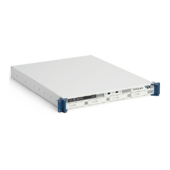
Page 15: Rmc-8357 Overview
ANSI C73.11/NEMA 5-15-P/IEC83 RMC-8357 Overview The RMC-8357 is a rugged 1U PC-based controller for remote control of PXI chassis. The controller provides leading-edge processing power with Intel Xeon E5-2620 v4 processors, high disk bandwidth with software RAID support, high I/O bandwidth with two PCI Express 3.0 x16 slots, and up to 32 GB of memory. -
Page 16: Blu-Ray
HDD indicator • System temp (overheat) and fan (fail) warning indicator System Management • Monitoring for CPU and chassis environment • CPU thermal trip support • +5 V standby alert LED • Fan speed control © National Instruments | 1-3... -
Page 17: Rmc-8357 Description
Chapter 1 Getting Started RMC-8357 Description Figures 1-1 1-2 and shows the key features of the RMC-8357 front and rear panels. For detailed information about the RMC-8357 front and rear panel, refer to Chapter 3, Information. Figure 1-1. Front View of the RMC-8357... - Page 18 RMC-8357 User Manual Figure 1-2. Rear View of the RMC-8357 IPMI Management Port LAN Ports DVI Port USB 3.0 Ports DisplayPort USB 2.0 Ports MXI x1 Ports 10 Serial Ports UID Switch 11 Power Connector VGA Port (Disabled By Default)
-
Page 19: Installation And Bios Setup
Installation and BIOS Setup This chapter describes how to install, configure, and use the RMC-8357. Read this chapter before connecting the RMC-8357 to a power source. Safety Information Before undertaking any troubleshooting, maintenance, or exploratory Caution procedure, carefully read the following caution notices. -
Page 20: Chassis Cooling Considerations
Air enters through the front of the chassis and exits through the fans on the rear of the chassis. Place the RMC-8357 on a bench top or in an instrument rack so that the fans (air outlets) and the air inlet apertures in the front and rear of the chassis have adequate ventilation. Keep other equipment a minimum of 76.2 mm (3 in.) away from the air outlets on the rear of the chassis. -
Page 21: Connecting Safety Ground
Chapter 5, Troubleshooting. Connecting Safety Ground The RMC-8357 is designed with a three-position IEC C14 style plug that connects the ground line to the chassis ground. To minimize shock hazard, make sure the electrical power outlet you use to power the chassis has an appropriate earth safety ground. -
Page 22: Starting The Bios Setup Utility
Do not upgrade the BIOS unless your system has a BIOS-related issue. Caution Flashing the wrong BIOS can cause irreparable damage to the system. In no event shall National Instruments be liable for direct, indirect, special, incidental, or consequential damages arising from a BIOS update. 2-4 | ni.com... -
Page 23: Main Setup
Take caution when changing the Advanced settings. An incorrect value, Caution a very high DRAM frequency, or an incorrect BIOS timing setting may cause the system to malfunction. When this occurs, restore the setting to the default setting. © National Instruments | 2-5... -
Page 24: Boot Feature
Chapter 2 Installation and BIOS Setup Boot Feature Quiet Boot Use this feature to select the screen display between the POST messages or the OEM logo at bootup. Select Disabled to display the POST messages. Select Enabled to display the OEM logo instead of the normal POST messages. -
Page 25: Watch Dog Function
Max (Maximum) CPU Speed • Min (Minimum) CPU Speed • Processor Max Ratio • Processor Min Ratio • Microcode Revision • L1 Cache RAM • L2 Cache RAM • L3 Cache RAM • CPU1 Version © National Instruments | 2-7... -
Page 26: Clock Spread Spectrum
Chapter 2 Installation and BIOS Setup Clock Spread Spectrum Select Enable for Clock Spectrum support, which will allow the BIOS to monitor and attempt to reduce the level of Electromagnetic Interference caused by the components whenever needed. Select Disabled to enhance system stability. The options are Disabled and Enabled. Hyper-Threading Select Enable to use Intel Hyper-Threading Technology to enhance CPU performance. -
Page 27: Dcu Streamer Prefetcher
8 bits to 16 bits to provide 512 APIDs to each thread to enhance CPU performance. The options are Disable and Enable. AES-NI Select Enable to use the Intel Advanced Encryption Standard (AES) New Instructions (NI) to ensure data security. The options are Enable and Disable. © National Instruments | 2-9... -
Page 28: Intel Virtualization Technology
Chapter 2 Installation and BIOS Setup Intel Virtualization Technology Select Enable to use Intel Virtualization Technology so that I/O device assignments will be reported directly to the VMM (Virtual Memory Management) through the DMAR ACPI Tables. This feature offers fully-protected I/O resource-sharing across the Intel platforms, providing the user with greater reliability, security and availability in networking and data-sharing. -
Page 29: Cpu C3 Report
The options are Enable and Disable. Long Duration Power Limit This item displays the power limit set by the user during which long duration power is maintained. The default setting is 0. © National Instruments | 2-11... - Page 30 Chapter 2 Installation and BIOS Setup Package Clamping Limit1 Use this item to set the limit on power performance states for the run-time processor, with P0 being the state with the highest frequency (clock speed) and power (consumption), and P1, a step lower in performance than P0, with its frequency and voltage scaled back a notch.
- Page 31 Select Enable to enable Relaxed Ordering support which will allow certain transactions to violate the strict-ordering rules of PCI and to be completed prior to other transactions that have already been enqueued. The options are Disable and Enable. © National Instruments | 2-13...
- Page 32 Chapter 2 Installation and BIOS Setup Intel VT for Directed I/O (VT-d) Select Enable to use Intel Virtualization Technology support for Direct I/O VT-d support by reporting the I/O device assignments to the VMM (Virtual Machine Monitor) through the DMAR ACPI Tables. This feature offers fully-protected I/O resource sharing across Intel platforms, providing greater reliability, security and availability in networking and data-sharing.
- Page 33 The options are Enabled and Disabled. DRAM RAPL (Running Average Power Limit) Baseline Use this feature to set the run-time power-limit baseline for DRAM modules. The options are Disable, DRAM RAPL Mode 0, and DRAM RAPL Mode 1. © National Instruments | 2-15...
-
Page 34: Memory Ras (Reliability_Availability_Serviceability) Configuration
Chapter 2 Installation and BIOS Setup Set Throttling Mode Throttling improves reliability and reduces power consumption in the processor via automatic voltage control during processor idle states. The options are Disabled and CLTT (Closed Loop Thermal Throttling). Socket Interleave Below 4GB Select Enabled for the memory above the 4G Address space to be split between two sockets. -
Page 35: Lockstep X4 Dimms
Select Enabled to support onboard legacy USB devices. Select Auto to disable legacy support if there are no legacy USB devices present. Select Disable to have all USB devices available for EFI applications only. The options are Enabled, Disabled and Auto. © National Instruments | 2-17... -
Page 36: Xhci Hand-Off
Chapter 2 Installation and BIOS Setup XHCI Hand-Off This is a work-around solution for operating systems that do not support XHCI (Extensible Host Controller Interface) hand-off. The XHCI ownership change should be claimed by the XHCI driver. The settings are Enabled and Disabled. EHCI Hand-Off This item is for operating systems that do not support Enhanced Host Controller Interface (EHCI) hand-off. -
Page 37: Sata Configuration
Use this item to specify if the SATA port specified by the user should be connected to a Solid State drive or a Hard Disk Drive. The options are Hard Disk Drive and Solid State Drive. © National Instruments | 2-19... - Page 38 Chapter 2 Installation and BIOS Setup If the item above "Configure SATA as" is set to IDE, the following items will display: Serial ATA Port 0 Port 5 This item indicates that a SATA port specified by the user is not installed or not present. Port 0 ~ Port 5 SATA Device Type Use this item to specify if the SATA port specified by the user should be connected to a Solid State drive or a Hard Disk Drive.
-
Page 39: Ssata Configuration
Port 0 ~ Port 3 Spin Up Device On an edge detect from 0 to 1, set this item to allow the PCH to start a COMRE- SET initialization to the device. The options are Enabled and Disabled. © National Instruments | 2-21... - Page 40 Chapter 2 Installation and BIOS Setup Port 0 ~ Port 3 sSATA Device Type Use this item to specify if the sSATA port specified by the user should be connected to a Solid State drive or a Hard Disk Drive. The options are Hard Disk Drive and Solid State Drive. If the item above "Configure sSATA as"...
-
Page 41: Server Me (Management Engine) Configuration
The options are Disabled and Enabled. PERR# Generation Support Select Enabled to allow a PCI device to generate a PERR (PCI/PCI-E Parity Error) number for a PCI bus error event. The options are Enabled and Disabled. © National Instruments | 2-23... -
Page 42: Serr# Generation Support
Chapter 2 Installation and BIOS Setup SERR# Generation Support Select Enabled to allow a PCI device to generate an SERR (System Error) number for a PCI bus error event. The options are Enabled and Disabled. Above 4G Decoding Select Enabled to decode a PCI device that supports 64-bit in the space above 4G Address. The options are Enabled and Disabled. -
Page 43: Onboard Lan Oprom
This feature specifies the base I/O port address and the Interrupt Request address of Serial Port 1 or Serial Port 2. Select Auto for the BIOS to automatically assign the base I/O and IRQ address to a serial port specified. © National Instruments | 2-25... -
Page 44: Serial Port 2 Attribute
Chapter 2 Installation and BIOS Setup The options for Serial Port 1 are Auto, (IO=3F8h; IRQ=4), (IO=3F8h; IRQ=3, 4, 5, 6, 7, 9, 10, 11, 12), (IO=2F8h; IRQ=3, 4, 5, 6, 7, 9, 10, 11, 12); (IO=3E8h; IRQ=3, 4, 5, 6, 7, 9, 10, 11, 12), and (IO=2E8h;... - Page 45 Use this feature to enable or disable legacy Console Redirection after BIOS POST. When set to Bootloader, legacy Console Redirection is disabled before booting the OS. When set to Always Enable, legacy Console Redirection remains enabled when booting the OS. The options are Always Enable and Bootloader. © National Instruments | 2-27...
-
Page 46: Sol/Com2 Console Redirection
Chapter 2 Installation and BIOS Setup SOL/COM2 Console Redirection Select Enabled to use the SOL port for Console Redirection. The options are Enabled and Disabled. If the item above set to Enabled, the following items will become available for user's configuration: SOL/COM2 Console Redirection Settings Use this feature to specify how the host computer will exchange data with the client computer,... - Page 47 Select Enabled to use a COM port selected by the user for EMS Console Redirection. The options are Enabled and Disabled. If the item above set to Enabled, the following items will become available for user's configuration: © National Instruments | 2-29...
-
Page 48: Ems Console Redirection Settings
Chapter 2 Installation and BIOS Setup EMS Console Redirection Settings This feature allows the user to specify how the host computer will exchange data with the client computer, which is the remote computer used by the user. Out-of-Band Management Port The feature selects a serial port in a client server to be used by the Microsoft Windows Emergency Management Services (EMS) to communicate with a remote host server. -
Page 49: Acpi Settings
The options are Enabled and Disabled. Runtime Error Logging Support Select Enabled to support Runtime Error Logging. The options are Enable and Disable. If this item is set to Enable, the following item will be available for configuration: © National Instruments | 2-31... -
Page 50: Memory Corrected Error Enabling
Chapter 2 Installation and BIOS Setup Memory Corrected Error Enabling Select Enable for the BIOS to correct a memory error if it is correctable. The options are Enable and Disable. Available when the item above Runtime Error Logging Support is set to Note Enable. -
Page 51: Ipmi
The following items will be displayed: IPMI LAN Selection This item displays the IPMI LAN setting. The default setting is Failover. IPMI Network Link Status This item displays the IPMI Network Link status. The default setting is Shared LAN. © National Instruments | 2-33... -
Page 52: Update Ipmi Lan Configuration
Chapter 2 Installation and BIOS Setup Update IPMI LAN Configuration Select Yes for the BIOS to implement all IP/MAC address changes at the next system boot. The options are No and Yes. Configuration Address Source This feature allows the user to select the source of the IP address for this computer. If Static is selected, you will need to know the IP address of this computer and enter it to the system manually in the field. -
Page 53: Secure Boot Menu
• UEFI Boot Order #2 • UEFI Boot Order #3 • UEFI Boot Order #4 • UEFI Boot Order #5 • UEFI Boot Order #6 • UEFI Boot Order #7 • UEFI Boot Order #8 © National Instruments | 2-35... -
Page 54: Add New Boot Option
Chapter 2 Installation and BIOS Setup Add New Boot Option This feature allows the user to add a new boot option to system boot priority features. Add Boot Option Use this item to specify the name of the driver that the new boot option is added to. Path for Boot Option This item is used to specify the path to the driver that the new boot option is added to. -
Page 55: Discard Changes
Table 2-1. BIOS Error Beep Codes Beep Code Error Message Description One beep Refresh Circuits have been reset. (Ready to power up.) Five short beeps and Memory error No memory is detected in one long beep the system © National Instruments | 2-37... -
Page 56: Os Reinstallation And Recovery
<F4> when video first appears during the boot process. • The RMC-8357 also ships with an OS recovery media you can use to reinstall your operating system onto your hard drive. If you need to reinstall your operating system, you can use the included OS recovery media. -
Page 57: Cleaning
• Bag of assorted fasteners. Installing the Inner Slides Install the inner slides to the RMC-8357 as shown in Figure 2-1. The following figure shows an example controller that may differ from Note your product. © National Instruments | 2-39... - Page 58 Chapter 2 Installation and BIOS Setup Figure 2-1. Installing Inner Slides Retaining Screw (x14) Inner Slide 2-40 | ni.com...
-
Page 59: Installing The Slide Mounting Brackets In The Rack
Installing the Slide Mounting Brackets in the Rack Install the slide mounting brackets in the rack as shown in Figure 2-2. Figure 2-2. Installing Slide Mounting Brackets in Rack Retaining Screw (x4) Washer (x8) Slide Mounting Bracket (x4) Nut (x4) © National Instruments | 2-41... -
Page 60: Installing The Outer Slides In The Rack
Chapter 2 Installation and BIOS Setup Installing the Outer Slides in the Rack Install the outer slides in the rack as shown in Figure 2-3. Figure 2-3. Installing Outer Slides in Rack Nut (x6) Outer Slide Retaining Screw (x6) 2-42 | ni.com... -
Page 61: Installing The Chassis Into The Rack
Push the inner slides, attached to the chassis, into the grooves of the outer slides in the rack and slide the RMC-8357 into the rack, as shown in Figure 2-4. The following figure shows an example controller that may differ from Note your product. -
Page 62: I/O Information
I/O Information This chapter describes the RMC-8357 I/O connectors. Front Panel Connectors Table 3-2 lists various peripherals and their corresponding RMC-8357 external connectors, bus interfaces, and functions. Table 3-1. RMC-8357 Front Panel Peripherals Overview Peripheral External Connector Description USB 4-pin Series A stacked receptacle USB 3.0 capable... -
Page 63: Universal Serial Bus
Chapter 3 I/O Information Figure 3-1 shows the rear panel layout of the RMC-8357. Figure 3-1. Rear Panel of the RMC-8357 IPMI Management Port LAN Ports DVI Port USB 3.0 Ports DisplayPort USB 2.0 Ports MXI x1 Ports 10 Serial Ports... -
Page 64: Serial
RMC-8357 User Manual Serial Figure 3-3 shows the location and pinouts for the serial connector on the RMC-8357. Table 3-4 lists and describes the serial connector signal. Figure 3-3. Serial Connector Location and Pinout Serial Table 3-4. Serial Connector Signals... -
Page 65: Vga
Chapter 3 I/O Information Figure 3-4 shows the location and pinouts for the VGA connector on the RMC-8357. Table 3-5 lists and describes the VGA connector signals. Figure 3-4. VGA Connector Location and Pinout Table 3-5. VGA Connector Signals Signal Name... -
Page 66: Ethernet
RMC-8357 User Manual Ethernet Figure 3-5 shows the location and pinouts for the Ethernet connectors on the RMC-8357. Table 3-6 lists and describes the Ethernet connector signals. Figure 3-5. Ethernet Connector Location and Pinout Ethernet Table 3-6. Ethernet Connector Signals... -
Page 67: Common Configuration Questions
LAN1 and LAN2. The hard drive LED lights when there is hard drive Front View of the activity on the RMC-8357. For more information, refer to Figure 1-1, RMC-8357. How do I check the configuration of the memory, hard drive, time/date, and so on? You can view these parameters in the BIOS setup. -
Page 68: Boot Options
Setup, for more information. Chassis Configuration How do I set up the RMC-8357 to work with my PXIe chassis? Configuration of the PXI system is handled through Measurement & Automation Explorer (MAX), included with the software pre-installed on your RMC-8357. MAX creates the file, which defines the layout and parameters of your PXI system. -
Page 69: Troubleshooting
Unplug the AC power cord from the controller and allow it to cool down before powering it on again. Things to Try: • Make sure the RMC-8357 is plugged in to a working power source. • Make sure the monitor is plugged into the DisplayPort or DVI port. The VGA port is disabled by default. - Page 70 Chapter 5 Troubleshooting My RMC-8357 boots fine until I get to Windows, at which point I cannot read the screen. This may include garbled output, white screen, black screen, or an out of synch message from the monitor. This problem usually results from having the video card output set past the limits of the monitor.
- Page 71 Restricted Access Location. Use the DC power cable provided with DC power supplies for VDC input. Caution Using the RMC-8357 in a manner not described in this document may Caution impair the protection the RMC-8357 provides. © National Instruments | A-1...
- Page 72 Appendix A Specifications Mainboard Socket LGA 2011 Chipset Xeon E5-2620 v4 Memory slots Eight 240-pin DIMM DDR4 slots PCI Express One PCI Express 3.0 x16 slot and one PCI Express 3.0 x16 slot (half height) SATA Four SATA III ports USB ports Four USB 3.0 ports, two USB 2.0 ports Video...
- Page 73 Mechanical Shock Operating 30 g, 11 ms Test Procedures Standard Operating IEC 68-2-27 Operational Random Frequency (Hz) Vibration Level 5 to 350 0.0002 g 350 to 500 -3 dB/octave 0.00014 g Total g = 0.31 © National Instruments | A-3...
- Page 74 Appendix A Specifications Operational Random Frequency (Hz) Vibration Level 5 to 100 0.02 g 100 to 200 -3 dB/octave 200 to 350 0.01 g 350 to 500 -3 dB/octave 0.007 g Total g = 2.46 Random Vibration Test Procedures Test Standard Operating IEC 68-2-64...
- Page 75 Refer to the product Declaration of Conformity (DoC) for additional regulatory compliance information. To obtain product certifications and the DoC for this product, visit ni.com/ , search by model number or product line, and click the appropriate link in certification the Certification column. © National Instruments | A-5...
- Page 76 At the end of the product life cycle, all products must be sent EU Customers to a WEEE recycling center. For more information about WEEE recycling centers, National Instruments WEEE initiatives, and compliance with WEEE Directive 2002/96/EC on Waste and Electronic Equipment, visit ni.com/environment/...
- Page 77 Hardware Configuration The RMC-8357 uses a Supermicro X10SRW-F motherboard. For detailed information about this motherboard visit www.supermicro.com © National Instruments | B-1...
- Page 78 • System Integration—If you have time constraints, limited in-house technical resources, or other project challenges, National Instruments Alliance Partner members can help. To learn more, call your local NI office or visit ni.com/alliance © National Instruments | C-1...
- Page 79 Appendix C NI Services Training and Certification—The NI training and certification program is the most • effective way to increase application development proficiency and productivity. Visit for more information. ni.com/training – The Skills Guide assists you in identifying the proficiency requirements of your current application and gives you options for obtaining those skills consistent with your time and budget constraints and personal learning preferences.
- Page 80 ACPI Advanced Configuration and Power Management Interface ANSI American National Standards Institute Application Programming Interface—A standardized set of subroutines or functions along with the parameters that a program can call. APIC Advanced Programmable Interrupt Controller © National Instruments | G-1...
- Page 81 Glossary ASCII American Standard Code for Information Exchange ASIC Application-Specific Integrated Circuit The specification formulated in the 1980s that defines the IDE drive interface. Bytes BIOS Basic Input/Output System—BIOS functions are the fundamental level of any PC or compatible computer. BIOS functions embody the basic operations needed for successful use of the computer’s hardware resources.
- Page 82 Intel Pentium. EEPROM Electronically Erasable Programmable Read Only Memory Electromagnetic Compatibility Electromagnetic Interference Enhanced Parallel Port Federal Communications Commission Gigabytes of memory GPIB General Purpose Interface Bus (IEEE 488) Hard Disk Drive Hertz; cycles per second © National Instruments | G-3...
- Page 83 Glossary Input/output—The techniques, media, and devices used to achieve communication between machines and users. Integrated Drive Electronics—Hard disk and built-in controller. IEEE Institute of Electrical and Electronics Engineers IRQ* Interrupt signal Industry Standard Architecture—The original PC bus architecture, specifically the 16-bit AT bus. Kilobytes of memory Local Area Network—Communications network that serves users within a confined geographical area.
- Page 84 RMC-8357 User Manual MTTR Mean Time to Repair Multisystem eXtension Interface NI-DAQ The National Instruments software for data acquisition instruments. NI-VISA The National Instruments implementation of the VISA standard—An interface-independent software that provides a unified programming interface for VXI, GPIB, and serial instruments.
- Page 85 Glossary Root Mean Squared Real Time Clock—An electronic circuit that maintains the time of day and also can provide timing signals for timesharing operations. SATA Serial-ATA. See also ATA. SCSI Small Computer System Inteface SDRAM A form of dynamic RAM memory that is about 20% faster than EDO RAM.
- Page 86 Virtual Instrument Software Architecture—A single interface library for controlling GPIB, VXI, RS232, and other types of instruments. VISA has been standardized by the VXI Plug&Play Systems Alliance. Versa Module Eurocard VME eXtensions for Instrumentation Watts Watchdog Timer © National Instruments | G-7...
- Page 87 (figure), 2-40 installation configuration and operation BIOS checking settings, 4-1 site considerations, 2-2 boot options, configuring controller, 4-2 unpacking the RMC-8357, 1-1 installing RMC-8356, 2-1 cables, power (table), 1-1 common configuration questions, 4-1 key features, 1-2 boot options, 4-2...
- Page 88 (table), 3-2 front panel LEDs, 4-1 connectors and signals, 3-2 hardware configuration, B-1 overview (table), 3-1 installing in rack (figure), 2-43 unpacking the RMC-8357, 1-1 key features, 1-2 overview, 1-2 peripheral expansion overview (table), 3-1 troubleshooting, 5-1 connector and signals, 3-4...
Need help?
Do you have a question about the RMC-8357 and is the answer not in the manual?
Questions and answers