Table of Contents
Advertisement
Quick Links
455 Balanced Regulator
455BAL-1
1.1 General
455BAL-1
455BAL-1
1.2.1 Test for Correct
Adjustment
455BAL-2
455BAL-2
455BAL-3
455BAL-4
455BAL-6
455BAL-6
Retainer Assembly
Disassembly
455BAL-7
455BAL-9
1.1 General
VIDEO
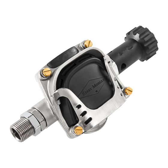
The 455 Balanced Regulator is an ultra-high per-
formance regulator, continuing the long line of
exceptional regulators from Kirby Morgan
construction and materials make it an extremely
rugged regulator.
When storing the helmet for any length
of time, ensure that the flex knob, for
adjusting the regulator, is turned "out" fully
counterclockwise to avoid stressing the bias
NOTE
spring. This will prolong the life of both the
inlet valve, seat, and bias spring.
© MMXXI Kirby Morgan Dive Systems, Inc. All rights reserved. Document # 210914002
455 Balanced Regulator
Contents
Kirby Morgan 455
Balanced Regulator
https://www.youtube.com/
watch?v=niLRuNUNmTw
. Its
®
455BAL-11
455BAL-13
455BAL-14 1.5 455 Balanced Regulator
Reassembly
455BAL-14
455BAL-16
455BAL-19
Reassembly
455BAL-22
455BAL-25
455BAL-27 1.6 Installing the 455 Balanced
Performance
The 455 Balanced Regulator is an all stainless
steel regulator of a balanced design that offers
far greater overall breathing performance than
the non-balanced SuperFlow
350 regulator.
1.2.1 Test for Correct Adjustment
Tools required:
• Regulated air supply, 135 to 150 psig
through Standard Scuba Second Stage Hose
To maintain optimum performance of the de-
mand regulator, it should be checked for proper
function and adjustment prior to commencement
of diving each diving day, in accordance with the
KMDSI Daily Set Up and Functional Checklist.
See the Kirby Morgan
General
and SuperFlow
®
or Dive Lab websites for
®
455BAL-1
®
Advertisement
Table of Contents

Subscribe to Our Youtube Channel
Related Manuals for Kirby Morgan 455


Summary of Contents for Kirby Morgan 455
-
Page 1: Table Of Contents
KMDSI Daily Set Up and Functional Checklist. See the Kirby Morgan or Dive Lab websites for ® 455BAL-1 © MMXXI Kirby Morgan Dive Systems, Inc. All rights reserved. Document # 210914002... -
Page 2: 455 Balanced Regulator Performance
2) Attach an L.P. regulated gas supply to regula- tor inlet or helmet side block. 4) Slowly turn on the gas supply. 3) Turn on gas supply slowly. 455BAL-2 © MMXXI Kirby Morgan Dive Systems, Inc. All rights reserved. Document # 210914002... -
Page 3: Adjusting The 455 Balanced Regulator
DIAPHRAGM JAM NUT EXHAUST VALVE INSERT REGULATOR REGULATOR PURGE COVER EXHAUST VALVE COVER RETAINER FRAME REGULATOR RETAINER RING COVER GUARD Exploded view of 455 Balanced regulator. 455BAL-3 © MMXXI Kirby Morgan Dive Systems, Inc. All rights reserved. Document # 210914002... -
Page 4: 455 Balanced Regulator Removal From Helmet
Be sure to at- tach an L.P. gas supply and test the regulator between adjustments. 455BAL-4 © MMXXI Kirby Morgan Dive Systems, Inc. All rights reserved. Document # 210914002... - Page 5 Remove the regulator from the helmet. 6) Cut the tie wrap that connects the quad valve 8) The center section of the exhaust flange on 455BAL-5 © MMXXI Kirby Morgan Dive Systems, Inc. All rights reserved. Document # 210914002...
-
Page 6: 455 Balanced Regulator Disassembly
Cover Guard and its associated mounting hard- Loosen the screws and washers on ware. either side of the cover. It is secured to the regulator body with four 455BAL-6 © MMXXI Kirby Morgan Dive Systems, Inc. All rights reserved. Document # 210914002... -
Page 7: Regulator Cover
• 15/ 1 6 inch Open End Wrench regulator cover. 1) Remove the bent tube assembly from the hel- met, per "1.3.1 Removal of the Bent Tube Assem- bly" on page BNT-4. 455BAL-7 © MMXXI Kirby Morgan Dive Systems, Inc. All rights reserved. Document # 210914002... - Page 8 It may be necessary to use a soft hammer to break the main tube loose from the regulator body. NOTE 455BAL-8 © MMXXI Kirby Morgan Dive Systems, Inc. All rights reserved. Document # 210914002...
-
Page 9: Flex Knob Disassembly
You can use a credit card, toothpick, or any clean soft device that will not damage the O-ring or the nut. Unscrew the flex knob assembly from the main tube. 455BAL-9 © MMXXI Kirby Morgan Dive Systems, Inc. All rights reserved. Document # 210914002... - Page 10 With the shaft out, the flex knob can be separated from the packing nut. 455BAL-10 © MMXXI Kirby Morgan Dive Systems, Inc. All rights reserved. Document # 210914002...
-
Page 11: Main Tube Components Disassembly
Check the condition of this O-ring very carefully. If there are any signs of damage, it must be replaced. Pay close attention to this NOTE seal! 455BAL-11 © MMXXI Kirby Morgan Dive Systems, Inc. All rights reserved. Document # 210914002... - Page 12 Carefully check the inlet nipple O-ring for damage, even small cuts may cause leaking. Inspect all parts for signs of wear or damage NOTE and replace if necessary. 455BAL-12 © MMXXI Kirby Morgan Dive Systems, Inc. All rights reserved. Document # 210914002...
-
Page 13: Regulator Body And Exhaust Disassembly
5) Remove the two port plugs and their O-rings and replace the O-rings. Use a small flat blade screwdriver to remove the exhaust valve insert retainer ring from the regulator body. 455BAL-13 © MMXXI Kirby Morgan Dive Systems, Inc. All rights reserved. Document # 210914002... - Page 14 Chris- to-Lube or equivalent oxygen compatible lu- ® S.S. REGULATOR BODY O-RING EXHAUST VALVE EXHAUST VALVE INSERT RETAINER RING 455 Balanced exhaust valve mechanism. 455BAL-14 © MMXXI Kirby Morgan Dive Systems, Inc. All rights reserved. Document # 210914002...
- Page 15 It should be difficult, to the proper side of the exhaust insert. or not able to turn. You should not be able to dis- 455BAL-15 © MMXXI Kirby Morgan Dive Systems, Inc. All rights reserved. Document # 210914002...
-
Page 16: Flex Knob Reassembly
O-ring into the adjustment pack- ing nut followed by the shaft bearing washer. Press the washer down with a finger to lock the components into the adjustment packing nut. 455BAL-16 © MMXXI Kirby Morgan Dive Systems, Inc. All rights reserved. Document # 210914002... - Page 17 Christo-Lube or equivalent oxygen compat- ® ible lubricant. Lightly lubricate the groove in the end of the flex knob. 455BAL-17 © MMXXI Kirby Morgan Dive Systems, Inc. All rights reserved. Document # 210914002...
- Page 18 Continue turning the flex knob counter- flex knob counterclockwise to engage threads clockwise until the flex knob stops. 6) Lubricate and install the external O-ring onto the adjustment packing nut. 455BAL-18 © MMXXI Kirby Morgan Dive Systems, Inc. All rights reserved. Document # 210914002...
-
Page 19: Main Tube Components
DO NOT OVER LUBRICATE THE O- RINGS ON THE BALANCE SPACER. Excess lubrication could possibly col- lect at the end of this part and block the critical air balancing hole. 455BAL-19 © MMXXI Kirby Morgan Dive Systems, Inc. All rights reserved. Document # 210914002... - Page 20 If it does not, the valve has not been inserted correctly. NOTE 455BAL-20 © MMXXI Kirby Morgan Dive Systems, Inc. All rights reserved. Document # 210914002...
- Page 21 ® bricant. Thread the flex knob assembly onto the main tube until it stops. 11) Install the bearing clip onto the outside of the main tube. 455BAL-21 © MMXXI Kirby Morgan Dive Systems, Inc. All rights reserved. Document # 210914002...
-
Page 22: Installing The Main Tube Into The Regulator Body
7/8 inch & 15/ 1 6 inch Open End Attachments • Christo-Lube or equivalent oxygen compat- ® ible lubricant 1) Confirm the main tube O-ring has been in- stalled and is lubricated. 455BAL-22 © MMXXI Kirby Morgan Dive Systems, Inc. All rights reserved. Document # 210914002... - Page 23 HEX flat area on the main tube aligns to the mating HEX in the regulator body. Make sure the nut on the adjustment knob is not tight against the regulator body. NOTE 455BAL-23 © MMXXI Kirby Morgan Dive Systems, Inc. All rights reserved. Document # 210914002...
- Page 24 The hex nut will have to be unscrewed a little NOTE more from the main tube to allow for correct installation. Reinstall the adapter and re torque. 455BAL-24 © MMXXI Kirby Morgan Dive Systems, Inc. All rights reserved. Document # 210914002...
-
Page 25: Regulator Cover Retainer Assembly Reassembly
It is secured to the regulator body with four stainless steel screws using a washer and lock washer configuration. The two lower screws can 455BAL-25 © MMXXI Kirby Morgan Dive Systems, Inc. All rights reserved. Document # 210914002... - Page 26 7) Place the diaphragm onto the regulator body. Ensure it is properly fitted into the recessed edge. 455BAL-26 © MMXXI Kirby Morgan Dive Systems, Inc. All rights reserved. Document # 210914002...
-
Page 27: Regulator Onto The Helmet
9) Torque the screws evenly, see "1.14 Regulator 1) Install the main exhaust body (with exhaust Torque Specifications" on page APNDX-33. whiskers attached) onto the exhaust flange of the regulator body. 455BAL-27 © MMXXI Kirby Morgan Dive Systems, Inc. All rights reserved. Document # 210914002... - Page 28 Install the tie wrap on the regulator. 455BAL-28 © MMXXI Kirby Morgan Dive Systems, Inc. All rights reserved. Document # 210914002...
- Page 29 Use a tooth brush to clean threads as needed. Lightly lubricate the regula- tor mounting tube threads and the sealing O-ring with Christo-Lube ® 455BAL-29 © MMXXI Kirby Morgan Dive Systems, Inc. All rights reserved. Document # 210914002...
- Page 30 Install the regulator mount nut. DO NOT FULLY TIGHTEN THE NUT AT THIS TIME. 9) Install the bent tube per "1.3.3 Installation of the Bent Tube Assembly" on page BNT-4. 455BAL-30 © MMXXI Kirby Morgan Dive Systems, Inc. All rights reserved. Document # 210914002...
- Page 31 13) Install the oral nasal mask per "1.1.3 Oral Nasal Mask Replacement" on page ON-2. 14) Install the nose block device per "1.2.2 Nose Block Device Replacement" on page FCPRT-6. 455BAL-31 © MMXXI Kirby Morgan Dive Systems, Inc. All rights reserved. Document # 210914002...
Need help?
Do you have a question about the 455 and is the answer not in the manual?
Questions and answers