Advertisement
Quick Links
455 Balanced Regulator
455BAL-1
1.1 General
455BAL-1
1.2 455 Balanced Regulator
Performance
455BAL-1
1.2.1 455 Balanced Demand
Regulator Test for Correct
Adjustment, Fully Assembled
455BAL-2
455BAL-4
1.1 General
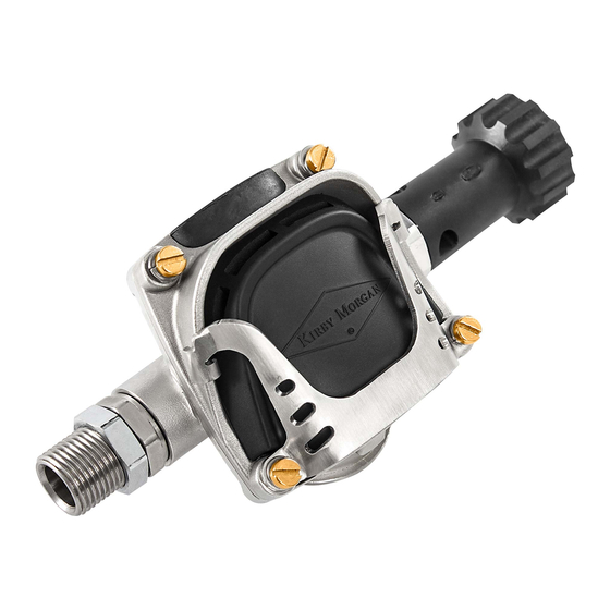
The 455 Balanced Regulator is an ultra-high per-
formance regulator, continuing the long line of
exceptional regulators from Kirby Morgan
construction and materials make it an extremely
rugged regulator.
NOTE: When storing the helmet for any length
of time, ensure that the Flex Knob, for adjusting
the regulator, is turned "out" fully counterclock-
wise to avoid stressing the bias springs. This will
prolong the life of both the inlet valve, seat, and
bias spring.
The 455 Balanced Regulator is an all stainless
steel regulator of a balanced design that offers
far greater overall breathing performance than
the non-balanced SuperFlow
350 regulator.
1.2.1 455 Balanced Demand Regulator
Test for Correct Adjustment, Fully
Assembled
To maintain optimum performance of the de-
mand regulator, it should be checked for proper
© MMXIX Kirby Morgan Dive Systems, Inc. All rights reserved. Document # 190619003
455 Balanced Regulator
Contents
. Its
®
and SuperFlow
®
®
455 Balanced Demand Regulator Test for Correct Adjustment, Fully Assembled
455BAL-13 1.4 455 Balanced Regulator
Removal
455BAL-15 1.5 455 Balanced Disassembly
455BAL-18 1.6 Assembly of the 455
Balanced Regulator
455BAL-18
455BAL-18
455BAL-20
455BAL-23
function and adjustment prior to commencement
of diving each diving day, in accordance with the
KMDSI Daily Set Up and Functional Checklist.
See the Kirby Morgan
the latest checklists at
www.divelab.com.
Check the regulator for adjustment and proper
function with the assembly complete, and sup-
plied with a breathing gas supply pressure of be-
tween 135 to 150 p.s.i.g
NOTE: 135 to 150 p.s.i.g. over ambient is the
standard supply pressure to be used when ad-
justing the 455 Balanced regulator.
1) Rotate the flex knob in, clockwise towards the
regulator body, until a clicking can be heard with
each full turn of the knob. This is an audible indi-
cation the tension of the bias adjustment spring
is as tight as it will get. The adjustment knob will
never bottom out or stop turning in this direction
and no damage to the mechanism will occur. The
clicking is an audible indication the adjustment
knob is fully positioned. Listen carefully for this
indicating click.
2) Ensure the supply pressure is connected and
properly adjusted to 135 to 150 p.s.i.g.
or Dive Lab websites for
®
www.kirbymorgan.com
455BAL-1
or
Advertisement

Subscribe to Our Youtube Channel
Related Manuals for Kirby Morgan 455


Summary of Contents for Kirby Morgan 455
-
Page 1: Table Of Contents
2) Ensure the supply pressure is connected and To maintain optimum performance of the de- properly adjusted to 135 to 150 p.s.i.g. mand regulator, it should be checked for proper 455BAL-1 © MMXIX Kirby Morgan Dive Systems, Inc. All rights reserved. Document # 190619003... -
Page 2: Adjusting The 455 Balanced Regulator
• 11/ 1 6 inch Open-End Attachment on Torque Wrench • 7/8 inch Open-End Attachment on Torque Wrench • 7/8 inch Open-End Wrench Remove the bent tube adapter 2) Remove the bent tube adapter. 455BAL-2 © MMXIX Kirby Morgan Dive Systems, Inc. All rights reserved. Document # 190619003... - Page 3 In- sert a 1/4 inch wide flat head screwdriver into the 455BAL-3 © MMXIX Kirby Morgan Dive Systems, Inc. All rights reserved. Document # 190619003...
-
Page 4: 455 Balanced Regulator Bias Adjustment Field Service With Demand Regulator On Helmet
DIAPHRAGM JAM NUT EXHAUST VALVE INSERT REGULATOR REGULATOR PURGE COVER EXHAUST VALVE COVER RETAINER FRAME REGULATOR RETAINER RING COVER GUARD Exploded view of 455 Balanced regulator. 455BAL-4 © MMXIX Kirby Morgan Dive Systems, Inc. All rights reserved. Document # 190619003... - Page 5 Un-thread the screws only enough to allow the cover assembly to separate from the main body of the regulator to expose the interior parts. 455BAL-5 © MMXIX Kirby Morgan Dive Systems, Inc. All rights reserved. Document # 190619003...
- Page 6 455 regulator body in the photo above are for manufacturer’s test purposes only. These two plugs should be left in place unless the O-rings require replacement. 455BAL-6 © MMXIX Kirby Morgan Dive Systems, Inc. All rights reserved. Document # 190619003...
- Page 7 Separate the flex knob assembly from the main tube. place if necessary. Otherwise, if it is in good con- dition, set it aside for cleaning and lubrication. 455BAL-7 © MMXIX Kirby Morgan Dive Systems, Inc. All rights reserved. Document # 190619003...
- Page 8 Remove the balance spacer, spring and inlet valve assembly from the main tube. 11) Slide the balance spacer, spring, and inlet valve assembly out from the main tube. 455BAL-8 © MMXIX Kirby Morgan Dive Systems, Inc. All rights reserved. Document # 190619003...
- Page 9 NOTE: The wings that align with the lever arm are the two that have an additional wall for the lever arm to bear on. The valve assembly should 455BAL-9 © MMXIX Kirby Morgan Dive Systems, Inc. All rights reserved. Document # 190619003...
- Page 10 24) With light pressure applied to the transfer 455BAL-10 © MMXIX Kirby Morgan Dive Systems, Inc. All rights reserved. Document # 190619003...
- Page 11 The rounded side faces toward the adjustment knob assembly. Thread the adjustment nipple into the main tube. Install the bearing clip onto the outside of the main tube. 455BAL-11 © MMXIX Kirby Morgan Dive Systems, Inc. All rights reserved. Document # 190619003...
- Page 12 Confirm three plus threads are visible on the inside of the regulator body. NOTE: It is important to do steps 30) and 31) in this sequence. 455BAL-12 © MMXIX Kirby Morgan Dive Systems, Inc. All rights reserved. Document # 190619003...
-
Page 13: 455 Balanced Regulator Performance
Be sure to remove and set aside the whisker spacers. correct Table (by model) in Appendix Contents, Torque Specs starting on page APNDX-19. 455BAL-13 © MMXIX Kirby Morgan Dive Systems, Inc. All rights reserved. Document # 190619003... - Page 14 6) Cut the tie wrap that connects the regulator body to the water dump tube on the helmet pod. Remove the tie wrap. 455BAL-14 © MMXIX Kirby Morgan Dive Systems, Inc. All rights reserved. Document # 190619003...
- Page 15 2) The adjustment shaft must be completely re- moved to allow the removal of the flex knob. DO 455BAL-15 © MMXIX Kirby Morgan Dive Systems, Inc. All rights reserved. Document # 190619003...
- Page 16 There is a boss on the knob that will pop loose from the packing nut. 455BAL-16 © MMXIX Kirby Morgan Dive Systems, Inc. All rights reserved. Document # 190619003...
- Page 17 Pay close attention to this seal! 455BAL-17 © MMXIX Kirby Morgan Dive Systems, Inc. All rights reserved. Document # 190619003...
-
Page 18: Assembly Of The Flex Knob
• 1 1/4 inch Flat Blade Attachment on Torque Screwdriver • 1/4–3/8 inch Flat Blade Screwdriver Insert the knob into the packing nut at an angle as shown using your hand or a vise. 455BAL-18 © MMXIX Kirby Morgan Dive Systems, Inc. All rights reserved. Document # 190619003... - Page 19 O-RING EXHAUST VALVE EXHAUST VALVE INSERT RETAINER RING 455 Balanced exhaust valve mechanism. 455BAL-19 © MMXIX Kirby Morgan Dive Systems, Inc. All rights reserved. Document # 190619003...
-
Page 20: Assembly Of 455 Balanced Regulator
1) Inspect the interior of the regulator body and make sure that it is clean and there is no foreign matter. 2) Install the O-ring for the exhaust valve insert, into the regulator body. 455BAL-20 © MMXIX Kirby Morgan Dive Systems, Inc. All rights reserved. Document # 190619003... - Page 21 Friction between the insert, the O-ring and the regulator body should hold the insert in its proper position. Also check to be 455BAL-21 © MMXIX Kirby Morgan Dive Systems, Inc. All rights reserved. Document # 190619003...
- Page 22 Install the diaphragm, cover assembly and cover retaining screws. 12) Install the diaphragm, cover assembly and cover retaining screws. Tighten the screws to 15 to 18 inch pounds. 455BAL-22 © MMXIX Kirby Morgan Dive Systems, Inc. All rights reserved. Document # 190619003...
-
Page 23: 455 Balanced Regulator Installation
1) Install the tie wrap on the center section of as shown, to the main exhaust body. the exhaust whisker, (the exhaust main body) and tighten. Remove excess tie wrap. 455BAL-23 © MMXIX Kirby Morgan Dive Systems, Inc. All rights reserved. Document # 190619003... - Page 24 4) Make sure the rubber tube is installed prop- erly on the water dump tube on the pod. 5) Install the bent tube assembly, per "1.3.3 In- 455BAL-24 © MMXIX Kirby Morgan Dive Systems, Inc. All rights reserved. Document # 190619003...
- Page 25 Tighten the screws in accordance with the torque specification found in the correct Table (correct model) of the manual Appendix. See Appendix Contents: Torque Specs starting on page APNDX-19. 455BAL-25 © MMXIX Kirby Morgan Dive Systems, Inc. All rights reserved. Document # 190619003...
Need help?
Do you have a question about the 455 and is the answer not in the manual?
Questions and answers