Advertisement
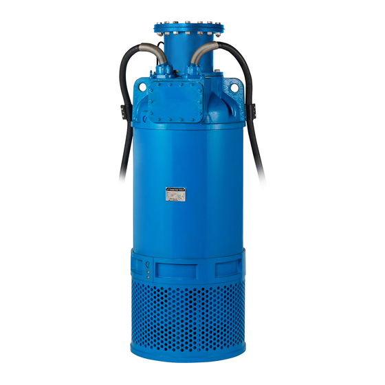
LH/LH-W Series
(LH6110 -51/61, LH8110 -51/61, LH4110W -51/61)
Submersible High-Head/Extra High-Head Dewatering Pumps
INTRODUCTION
Thank you for selecting the Tsurumi LH/LH-W Series submersible high-head/extra high-head dewatering
pumps.
This operation manual explains the product operations and gives important precautions regarding its safe
use. In order to use the product to maximum benefit, be sure to read the instructions thoroughly and follow
them carefully.
To avoid accident, do not use the pump in any way other than as described in this operation manual. Note
that the manufacturer cannot be responsible for accidents arising because the product was not used as
prescribed. After reading this operation manual, keep it nearby as a reference in case questions arise during
use.
When lending this product to another party, always be sure to include this operation manual as well.
If this operation manual should become lost or damaged, ask your nearest dealer or Tsurumi representative
for another copy.
Every effort has been made to ensure the completeness and accuracy of this document. Please contact your
nearest dealer or Tsurumi representative if you notice any possible error or omission.
The contents of this document may not be copied in whole or in part without the express permission of
Tsurumi Manufacturing Co., Ltd.
TSURUMI MANUFACTURING CO., LTD.
OPERATION MANUAL
1. BE SURE TO READ FOR YOUR SAFETY ..................... 1
2. NAME OF PARTS .......................................................... 4
3. PRIOR TO OPERATION ............................................... 5
4. INSTALLATION ............................................................. 6
5. ELECTRICAL WIRING .................................................... 7
6. OPERATION .................................................................... 9
7. MAINTENANCE AND INSPECTION ............................... 11
8. DISASSEMBLY AND REASSEMBLY ............................. 13
9. TROUBLESHOOTING .................................................. 18
CONTENTS
17200470/B-10224-1
Advertisement
Table of Contents

Subscribe to Our Youtube Channel
Related Manuals for Tsurumi Pump LH Series


Summary of Contents for Tsurumi Pump LH Series
-
Page 1: Table Of Contents
17200470/B-10224-1 LH/LH-W Series (LH6110 -51/61, LH8110 -51/61, LH4110W -51/61) Submersible High-Head/Extra High-Head Dewatering Pumps OPERATION MANUAL INTRODUCTION Thank you for selecting the Tsurumi LH/LH-W Series submersible high-head/extra high-head dewatering pumps. This operation manual explains the product operations and gives important precautions regarding its safe use. -
Page 2: Be Sure To Read For Your Safety
1 BE SURE TO READ FOR YOUR SAFETY Be sure to thoroughly read and understand the SAFETY PRECAUTIONS given in this section before using the equipment in order to operate the equipment correctly. The precautionary measures described in this section are intended to prevent danger or damage to you or to others. - Page 3 CAUTION • Provide a secure ground. Do not connect • Install the discharge piping the grounding wire to a gas pipe, water securely so that no water leakage pipe, lightning rod, or telephone may occur. Failure to do so may ground line.
- Page 4 CAUTION • Never insert a finger or any other • When the product will not be used for an object into the pump inlet holes. extended period, be sure to turn off the Failure to observe this caution power supply (earth leakage circuit may lead to injury.
-
Page 5: Name Of Parts
2 NAME OF PARTS Model LH6110 / 8110 Discharge Pipe Lifting Eye Bolt Cabtyre Cable Mechanical Seal Oil Lifter Leakage Sensor Electrode Shaft Upper Shaft Sleeve Bearing Housing Oil Plug Lower Shaft Sleeve Oil Casing Labyrinth Ring Upper Pump Casing Impeller Lower Pump Casing Suction Mouth... -
Page 6: Prior To Operation
3 PRIOR TO OPERATION When the pump is delivered, first perform the following checks. Inspection While unpacking, inspect the product for damage during shipment, and make sure all bolts and nuts are tightened properly. Specification Check Check the model number to make sure it is the product that was ordered. Be certain it is the correct voltage and frequency. -
Page 7: Installation
Standard specifications (50/60Hz) Model Bore Phase Starting Method Output Max.HEAD Max.CAPACITY Weight m (feet) /min(GPM) LH6110 Star Delta 177/184 (581/604) 3.0/2.7 (793/713) 1210 LH8110 Star Delta 107/114 (351/374) 6.5 (1717) 1210 LH4110W Star Delta 216/230 (709/755) 2.0 (528) 1270 Note: The weight (mass) given above is the operating weight of the pump itself, not including the cabtyre cable. -
Page 8: Electrical Wiring
(1) Avoid dropping the pump or other strong impact. Lift the pump by attaching a rope or chain to the eye bolts. Wire Rope Note: On cabtyre cable handling, see below at Electrical Wiring (p.7) Eyebolt CAUTION Avoid dry operation, which will not only lower performance but can cause the pump to malfuncton, leading to electrical leakage and shock. - Page 9 Grounding WARNING Do not use the pump without first grounding it properly. Failure to ground it can lead to electrical shock from an electrical leak or pump malfunction. CAUTION Do not attach the grounding wire to a gas pipe, water pipe, lightening arrestor or telephone grounding wire.
-
Page 10: Operation
6 OPERATION Before starting (1) Make sure once again that the product is of the correct voltage and frequency rating. CAUTION Using the product at other than rated voltage and frequency will not only lower its performance but may damage the product. Note: Conf rm the rated voltage and frequency on the model name plate. - Page 11 Operation WARNING • The pump may become very hot during operation. Be careful not to contact the pump accidentally to avoid being burned. • To avoid serious injury, do not insert a finger or any other object in the pump inlet holes. •...
-
Page 12: Maintenance And Inspection
7 MAINTENANCE AND INSPECTION Regular maintenance and inspections are a necessity for continued efficient functioning of the pump. If any abnormal conditions are noticed, refer to the section on Troubleshooting(p.18) and take corrective measures immediately. It is recommended that a spare pump be kept ready in case of any problems. Prior to inspection WARNING Detach the cabtyre cable from the receptacle or terminals, after making... - Page 13 Oil inspection and Oil change WARNING When the pump is tilted for inspecting or changing the oil, pay careful attention to the Oil Inlet center of gravity and weight of the pump. When O-Ring lowering the pump, fasten the chain or rope to Oil Plug the eyebolts providerd for this purpose.
-
Page 14: Disassembly And Reassembly
Replacement Parts The table lists the parts that need to be replaced periodically. Replace these using the recommended frequency as a guideline. Recommended Frequency Part Mechanical Seal When oil in oil compartment becomes milky. Every 6,000 hours of 12 months, whichever comes first. Oil (Turbine Oil VG 32 ) Bearing Grease At overhaul... - Page 15 Exploded View [ LH6110 / 8110 ] O-Ring Oil Casing Lower Pump Casing Spring Washer Spring Washer O-Ring Hex.Bolt Hex.Nut Stud Bolt Hex.Bolt Upper Shaft Sleeve O-Ring Lower Shaft Suction Mouth Sleeve Packing Suction Mouth O-Ring Hex.Nut O-Ring Spring Washer Spring Washer O-Ring Grease Plug...
- Page 16 Note: Apply liquid gasket (Three Bond TB1207B or equivalent) on the lower pump casing when assembling the pump. The place to be applied is the top part of the casing (It is f lled with black in the drawing below). LH6110 LH8110 The place to be applied is the top part of the casing. It is the part filled with black in the drawing.
- Page 17 Exploded View [ LH4110W ] O-Ring Hex.Nut Impeller Adjusting Spring Washer Washer Upper Pump Casing Lower Impeller Spring Washer Mouth Ring Hex.Nut O-Ring Plain Washer Hex.Nut Impeller.Nut Upper Labyrinth Ring Lower O-Ring Packing Pump Mouth Ring Grease Plug Stud Bolt Casing O-Ring Impeller Adjusting...
- Page 18 Note: Apply liquid gasket (Three Bond TB1207B or equivalent) on the middle pump casing and the lower pump casing when assembling the pump. The place to be applied is the top part of each casing (It is f lled with black in the drawing below).
-
Page 19: Troubleshooting
9 TROUBLESHOOTING WARNING Always turn off the power before inspecting the pump. Failure to observe this precaution can result in serious accident. Before ordering repairs, carefully read through this operation manual, then repeat the inspection. If the probrem remains, contact your nearest dealer or Tsurumi representative. Problem Possible cause Countermeasure... - Page 20 A535801 SUPPLEMENTARY INSTRUCTIONS MANUAL FOR LH12185 PRIOR TO OPERATION Product Specifications Do not operate this product under any conditions other than those for CAUTION which it is specified. Failure to observe this precaution can lead to electrical shock, electrical leakage, fire, water leakage or other problems. ・Major Standard Specifications Rain Water, Ground Water, Sand laden Water, Applicable Liquids...
- Page 21 ELECTRICAL WIRING Connecting the cabtyre cable Before connecting leads to the terminals, make certain the power supply is WARNING turned off (circuit breaker, etc.), to avoid electrical shock, shorting, or unexpected staring of the pump, leading to injury. Do not use the pump if the cabtyre cable is worn or damaged, which can CAUTION result in electric shock, shorting, or fire.
- Page 22 Replacing bearing grease Models with output 185kW require that bearing grease be replaced periodically. With the pump standing upright, supply and drain grease at the grease nipple on the bearing housing side of lower bearing, and at the grease nipple on the motor bracket side of upper bearing.
Need help?
Do you have a question about the LH Series and is the answer not in the manual?
Questions and answers