Schaller Automation Visatron VN2020 Operating Manual
Oil mist detector
Hide thumbs
Also See for Visatron VN2020:
- Operating manual (95 pages) ,
- Operating manual (193 pages) ,
- Manual (98 pages)

Related Manuals for Schaller Automation Visatron VN2020


Summary of Contents for Schaller Automation Visatron VN2020
- Page 1 Oil mist detector ® Visatron VN2020 ® Visatron VN2020 Ex - Operating manual - - 183001 -...
- Page 2 Operating manual for the VISATRON VN2020 V2.0 12/2021 EN Page 2 of 106 SCHALLER AUTOMATION 66440 Blieskastel / Saarland / Germany / Industriering 14 / P.O. Box 1280 el. +49(0)6842-508-0 / Fax -260 / Email: info@schaller.de / Industrielle Automationstechnik GmbH & Co. KG...
- Page 3 Operating manual for the VISATRON VN2020 V2.0 12/2021 EN Dear customer, this operating manual is intended for all those who work/will work on/with the system described here. They require knowledge of this operating manual to avoid faults in the system and to operate the system without issues.
-
Page 4: Table Of Contents
Operating manual for the VISATRON VN2020 V2.0 12/2021 EN Table of contents Technical data and scope of delivery ..............7 Identification ..................... 10 2.1. Product brand and type designation ..............10 2.2. Manufacturer ....................10 Product description and technical data ............. 11 3.1. - Page 5 Operating manual for the VISATRON VN2020 V2.0 12/2021 EN 7.8. Installing the electrical connecting cable ............39 7.9. Installing the Remote Indicator (optional) ............43 7.10. Starting up for the first time ................45 7.10.1. Setting the negative pressure at the measuring head ........45 7.10.2.
- Page 6 Operating manual for the VISATRON VN2020 V2.0 12/2021 EN 10.1.3. Replacing the filter control valve ..............77 10.1.4. Replacing the connecting hose ................ 80 10.1.5. Replacing the seal for the inspection cover ............81 10.1.6. Replacing the seal for the mounting plate ............83 10.1.7.
-
Page 7: Technical Data And Scope Of Delivery
Operating manual for the VISATRON VN2020 V2.0 12/2021 EN 1. Technical data and scope of delivery Page 7 of 106 SCHALLER AUTOMATION 66440 Blieskastel / Saarland / Germany / Industriering 14 / P.O. Box 1280 el. +49(0)6842-508-0 / Fax -260 / Email: info@schaller.de / Industrielle Automationstechnik GmbH &... - Page 8 Operating manual for the VISATRON VN2020 V2.0 12/2021 EN Mechanical interfaces Dimensions Approx. 539 x 298 x 171 mm Weight 12.41 kg External thread M16x1.5 Pipe connection, diameter size 10 External thread M30x2 Pipe connection, diameter size 22 External thread M30x2...
- Page 9 Operating manual for the VISATRON VN2020 V2.0 12/2021 EN Pneumatic interfaces External thread M16x1.5 Pipe connection, diameter size 10 Compressed air supply Min. 2 bar Max. 14 bar Compressed air consumption 1.2 nm³/h ± 10% Value may vary depending on customer...
-
Page 10: Identification
Operating manual for the VISATRON VN2020 V2.0 12/2021 EN 2. Identification 2.1. Product brand and type designation This operating manual is for the VISATRON®-branded, series VN2020 oil mist detector. The oil mist detector is available in two product variants: •... -
Page 11: Product Description And Technical Data
During normal engine operation, the oil mist detector draws in any existing oil mist. This oil mist can settle in the suction lines. Schaller Automation uses a drainage concept at this point and returns the excess oil back to the engine crankcase. -
Page 12: Oil Mist Detection System
Operating manual for the VISATRON VN2020 V2.0 12/2021 EN 4. Oil mist detection system An oil mist detection system, referred to as an installation kit, usually consists of the following for delivery and is configured to customer specifications. Figure 1 shows the typical installation setup for a VN2020 installation kit for a six-cylinder engine. -
Page 13: Oil Mist Detector Vn2020
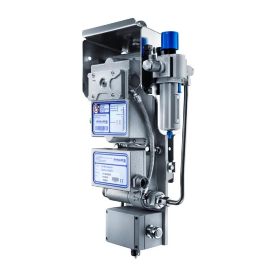
Operating manual for the VISATRON VN2020 V2.0 12/2021 EN 4.1. Oil mist detector VN2020 Figure 2: Oil mist detector VN2020 Base plate Connection box Measuring head Inspection cover Protective hood Air jet pump (Venturi principle) Type plate of the oil mist detector... - Page 14 Operating manual for the VISATRON VN2020 V2.0 12/2021 EN Two product variants of the VISATRON® VN2020-series oil mist detector are available: VN2020 VN2020 EX Figure 3: VN2020 Figure 4: VN2020 EX WARNING! Explosion of the crankcase Serious injury, including death ➔...
- Page 15 Operating manual for the VISATRON VN2020 V2.0 12/2021 EN The oil mist detector complies with classification II (2G) [Ex op is IIB T4 Gb]. +5°≤+70°C Equipment Protection Level Temperature Class (Maximum Surface Temperature) T4=135° Gas Group-Ethylene (Classified according to the ignitability)
- Page 16 Operating manual for the VISATRON VN2020 V2.0 12/2021 EN Control Room Engine Room Remote Indicator II Remote Indicator RS485 Alarm monitoring system Engine safety system Modbus RTU/CANopen Figure 5: Interface schematic The device can be connected directly to the engine’s safety system. The interface contains two oil mist alarm outputs, a pre-alarm output and a Ready signal.
-
Page 17: Bracket
4.3. Header pipes Schaller Automation uses state-of-the-art hydraulic components to draw in and transport oil mist atmospheres. Only tubes according to DIN EN 10305-4 and fittings according to EN ISO 8434-1 are therefore used in the installation kit. -
Page 18: Engine Wall Screw Connection And Suction Funnel
The fitting body allows for angular adjustment to accommodate the suction lines and forms the connection between the header pipes, suction lines and the crankcase. Schaller Automation offers engine wall screw fittings in various versions and specifically depending on the engine peripherals. -
Page 19: Hose Lines
4.6. Hose lines Hose lines can also be used as an alternative to the suction and exhaust air pipes. The hose lines used by Schaller Automation consist of a hydraulic hose with an additional coating of galvanised wire mesh. Figure 8: Hose line with wire mesh The hose lines are available with certificates from classification societies and authorities. -
Page 20: Optional Accessories
The connection to the customer’s monitoring systems is via a three-wire RS485 bus line. Figure 10: Remote Indicator II Schaller Automation has also integrated the VISATRON® devices into the operator’s automation system. A connection is possible via CANopen or MODBUS/RTU. -
Page 21: Safety And Protection Measures
V2.0 12/2021 EN 5. Safety and protection measures VN2020-series oil mist detectors are manufactured according to Schaller Automation’s high quality standards and are tested in strict factory tests. The safety instructions and warnings must be observed by the operator to ensure that the device operates smoothly and without problems. -
Page 22: Guide To Symbols
Operating manual for the VISATRON VN2020 V2.0 12/2021 EN 5.3. Guide to symbols This operating manual uses the following symbols in accordance with DIN EN 82079-1. ATTENTION: Indicates important information which helps to avoid damage to property. CAUTION: Indicates a low-risk hazard that, if not avoided, may result in minor or moderate injury. -
Page 23: Installation
Operating manual for the VISATRON VN2020 V2.0 12/2021 EN 6. Installation 6.1. Safety precautions before use DANGER! Explosion of the crankcase Serious injury, including death ➔ You may only install and remove the oil mist detection system when the engine is switched off. -
Page 24: Unpacking, Items Included In Delivery
6.2. Unpacking, items included in delivery When the oil mist detection system is delivered, always check the delivery to ensure that it includes all the components. Schaller Automation provides you with a corresponding parts list for this purpose. Dispose of the packaging materials in accordance with your local disposal regulations in the containers provided for this purpose. -
Page 25: Connecting The Compressed Air Supply
Operating manual for the VISATRON VN2020 V2.0 12/2021 EN 6.5. Connecting the compressed air supply The customer must provide a compressed air supply at a quality in accordance with ISO 8573-1:2010 – 6-4-4 and install it up to the oil mist detector. -
Page 26: Connecting The Electrical Power Supply
Alternative sizes of cable glands on request. 6.7. Mounting holes on crankcase In general, all components of the Schaller Automation oil mist detection system are mounted on the crankcase with a threaded hole. The thread size may vary, depending on the engine manufacturer and engine type. -
Page 27: Installation Of The Oil Mist Detector
Operating manual for the VISATRON VN2020 V2.0 12/2021 EN 7. Installation of the oil mist detector 7.1. Installing the oil mist detector with pre-assembled bracket Attach the oil mist detector to the engine using the pre-assembled, engine-specific bracket and with the supplied screws to the mounting holes provided for this purpose. Details of mounting and position can be found in the applicable customer drawing. -
Page 28: Installing The Engine Wall Screw Fittings And Suction Funnel
Operating manual for the VISATRON VN2020 V2.0 12/2021 EN 7.3. Installing the engine wall screw fittings and suction funnel Material number: 270354 (standard) Figure 14: Engine wall screw fitting (1) Suction funnel (2) Screw-in sleeve (3) Housing (4) Lock nut... - Page 29 Operating manual for the VISATRON VN2020 V2.0 12/2021 EN Recommended Suction funnel Splashing oil Engine wall Crankshaft Figure 15: Screw-in sleeve and housing Figure 16: Insert the suction funnel Screw the screw-in sleeve with flat gasket Insert the suction funnel through the inside of and housing into the mounting thread of the the crankcase into the screw-in sleeve.
- Page 30 Operating manual for the VISATRON VN2020 V2.0 12/2021 EN Figure 18: Connect line Figure 17: Align the suction funnel While tightening, align the suction funnel Connect the pipe or hose line with the vertically and with the opening pointing to the screw-in fitting of the engine wall screw fitting.
-
Page 31: Installing The Siphon Block
Operating manual for the VISATRON VN2020 V2.0 12/2021 EN 7.4. Installing the siphon block 150260 – Siphon block Material numbers: 150166 – Siphon block with measuring connection 270923 – Connection unit 03 Standard 270371 – Filling pump Figure 19: Siphon block... - Page 32 Operating manual for the VISATRON VN2020 V2.0 12/2021 EN Figure 24: Screws with Loctite 243 Figure 23: Connecting unit Remove the yellow protective caps of Apply Loctite 243 to both threads. the connecting unit and dispose of them. Figure 25: Mount the connecting unit...
- Page 33 Operating manual for the VISATRON VN2020 V2.0 12/2021 EN Figure 27: Remove protective caps Figure 28: Push in the siphon block Remove the protective caps (x4) from the Guide the siphon block over the pipe of the screws on the siphon block and dispose of suction funnel to the connecting unit.
- Page 34 Operating manual for the VISATRON VN2020 V2.0 12/2021 EN Figure 32: Mount filling pump Figure 31: Fill lubrication oil into filling pump Fill the filling pump with lubrication oil Insert the filling pump into the oil (lubrication oil approved by the engine...
- Page 35 Operating manual for the VISATRON VN2020 V2.0 12/2021 EN Figure 34: Remove filling pump Figure 33: Pump lubrication oil Perform eight slow and steady pump After filling the siphon block, remove strokes. the filling pump and screw in the screw plug again without delay.
-
Page 36: Installing The Canister Siphon
Operating manual for the VISATRON VN2020 V2.0 12/2021 EN 7.5. Installing the canister siphon Material number: 150939 Figure 35: Canister siphon (1) Canister siphon (2) Straight screw-in socket L22 (3) Union nut (4) Protective cap (5) Straight screw-in socket L10... - Page 37 Operating manual for the VISATRON VN2020 V2.0 12/2021 EN Figure 36: Mount screw-in socket Figure 37: Mount canister siphon Screw the straight screw-in socket (2) into Push the canister siphon (1) flush with the the thread of the crankcase. Tighten to 180 pipe attachment into the screw connection and initially fit the union nut hand-tight.
-
Page 38: Installing The Pipes
Tighten the union nut initially by hand. 7.6. Installing the pipes Schaller Automation uses standardised fittings in accordance with ISO 8434-1 for its installation kits. The cutting ring fittings used must be assembled and disassembled in accordance with ISO 8434-1. -
Page 39: Installation Of The Hose Lines
Operating manual for the VISATRON VN2020 V2.0 12/2021 EN 7.7. Installation of the hose lines The hose lines are installed according to the installation kit drawing. The length, angle, orientation and position of the lines can vary from engine type to engine type. - Page 40 Operating manual for the VISATRON VN2020 V2.0 12/2021 EN • Slotted screwdriver, width 2.5 mm Procedure for connecting the connecting line to the terminal box: Wire break Connections for resistors relays Cable entry Power supply Remote indicator connection Figure 43: Terminal box front view...
- Page 41 Operating manual for the VISATRON VN2020 V2.0 12/2021 EN Select a suitable resistor and replace Connect the connecting line to the installed resistors, if necessary. terminal blocks according to the wiring diagram. Table 1. Figure 49: Install the cover of the terminal box Figure 48: Connecting earth (example) Earth connection.
- Page 42 Operating manual for the VISATRON VN2020 V2.0 12/2021 EN Terminal Terminal Connect to Note/action 24 V DC + Power supply Voltage range: 18-31.2 V 24 V DC - Spare S1 Reserve Spare S2 RS485 A/CAN H Remote indicator RS485 B/CAN L...
-
Page 43: Installing The Remote Indicator (Optional)
The Schaller Remote Indicator II can be connected as a monitoring device for this purpose. In the event of an oil mist alarm, Schaller Automation strongly recommends (as described in IACS UR M10.7) not to approach the engine or carry out inspection work on the crankcase until it has cooled down sufficiently after the engine has stopped. - Page 44 V2.0 12/2021 EN Use a communication cable with a twisted and shielded 3-wire cable. SCHALLER AUTOMATION recommends LAPPKABEL UNITRONIC-FD CP (TP) plus UL-CSA. Maximum cable length of 400 m. The connection between oil mist detector and monitoring device for standard applications is shown in the following wiring diagram (see Figure 52).
-
Page 45: Starting Up For The First Time
Operating manual for the VISATRON VN2020 V2.0 12/2021 EN 7.10. Starting up for the first time WARNING! Engine protection not guaranteed Risk of oil mist explosion ➔ The oil mist detector may only be started up after all the components have been completely installed. - Page 46 Operating manual for the VISATRON VN2020 V2.0 12/2021 EN Procedure for setting the negative pressure on the measuring head: Figure 54: Inspection cover with screw Figure 55: Inspection cover with quick- plug release coupling Unscrew the screw plug (3) on the inspection...
- Page 47 Operating manual for the VISATRON VN2020 V2.0 12/2021 EN Figure 59: Negative pressure display on Figure 58: Pressure indicator the U-tube manometer Switch on the compressed air supply. Set 60 mmH2O ±5 mmH2O. To do this, Observe the permissible supply adjust the adjusting screw on the filter pressure.
-
Page 48: Connecting The Power Supply
Operating manual for the VISATRON VN2020 V2.0 12/2021 EN 7.10.2. Connecting the power supply The power supply must be provided by the operator for the following steps. (1) Switch on the power supply for the oil mist detector. (2) The LEDs on the display of the measuring head flash immediately after you switch on the power supply. -
Page 49: Function Test During Startup
Operating manual for the VISATRON VN2020 V2.0 12/2021 EN 7.10.4. Function test during startup Once the steps in Sections 7.10.1 to 7.10.3 have been successfully completed, you can start the function test. (1) Remove the smoke tube from the Smoketest Box (Section 14.3) and bend the smoke tube. -
Page 50: Checklist For Startup
Operating manual for the VISATRON VN2020 V2.0 12/2021 EN 7.10.5. Checklist for startup Item Description Are all lines and pipes installed as shown in the installation drawing? Are all screw connections tightened to the correct torque? If mounting with siphon blocks: Are all siphon blocks filled with oil and all... -
Page 51: Operation And Application
Operating manual for the VISATRON VN2020 V2.0 12/2021 EN 8. Operation and application 8.1. Display and alarm reset If the oil mist concentration is high, the LED indicator will increase and at 70% opacity of the set alarm threshold, the “Oil Mist Alarm” LED comes on. At 100% opacity relative to the set alarm threshold, the “Oil Mist Alarm”... -
Page 52: Error Diagnosis And Troubleshooting
Operating manual for the VISATRON VN2020 V2.0 12/2021 EN 8.2. Error diagnosis and troubleshooting If an internal device error or system error occurs, the diagnostic system displays the error code via the 2-LED numerical display. The “Ready” LED is switched off by the system and... -
Page 53: Error Code - All Leds Off
Operating manual for the VISATRON VN2020 V2.0 12/2021 EN The displayed faults can be resolved by the customer or alternatively by an authorised Schaller service partner. The error codes and troubleshooting steps are listed in their order of priority below. The specified work steps must be carried out one after the other, if the previous work step in each case has not cancelled the error code. -
Page 54: Error Code 11 - Ambient Temperature Too Low (< 0 °C)
Operating manual for the VISATRON VN2020 V2.0 12/2021 EN 8.2.10. Error code 11 – Ambient temperature too low (< 0 °C) 1. Remove or relocate objects nearby that are cooling 8.2.11. Error code 12/17 – Internal memory checksum error 1. Replace the measuring head (Section 10.1.1) 2. -
Page 55: Maintenance And Repair
Operating manual for the VISATRON VN2020 V2.0 12/2021 EN Maintenance and repair The following warning and safety instructions must always be observed for all maintenance and repair work. WARNING! Severe injury due to hot atmosphere escaping from crankcase Risk of burns ➔... - Page 56 Operating manual for the VISATRON VN2020 V2.0 12/2021 EN Description Interval (whichever occurs first) Hours Or months 12 18 24 Check negative pressure in the measuring head: ➔ below 55 mmH2O (5.5mbar) ➔ Adjust negative pressure 270532 ➔ Between 55 mmH2O and...
-
Page 57: Maintenance By The Operator
9.1.2. Maintenance by the operator WARNING! Risk of explosion Severe to fatal injuries due to oil mist explosion ➔ Only use Schaller Automation original spare parts. 9.1.3. Cleaning the light path (4,000 h) ATTENTION! Premature failure of the oil mist detector Dirty parts increase the risk of equipment failure. - Page 58 Operating manual for the VISATRON VN2020 V2.0 12/2021 EN Figure 67: Clean photodiode Figure 68: Clean sealing surface Clean the photodiode Clean the sealing surface of the inspection cover seal Figure 69: New inspection cover seal Figure 70: Fit the inspection cover Position a new seal for the inspection Place the inspection cover onto the seal.
- Page 59 Operating manual for the VISATRON VN2020 V2.0 12/2021 EN Figure 71: Tighten the inspection cover screws Tighten the captive screws crosswise to a torque of 4.5 Nm. Page 59 of 106 SCHALLER AUTOMATION 66440 Blieskastel / Saarland / Germany / Industriering 14 / P.O. Box 1280 el.
-
Page 60: Function Test With Smoke Tube
Operating manual for the VISATRON VN2020 V2.0 12/2021 EN 9.1.4. Function test with smoke tube ATTENTION! Before a function test, you must make sure that the oil mist detector has been correctly maintained. Only carry out the function test with the engine at a standstill (if the engine is running, it will automatically stop or go into slow-down mode). - Page 61 Operating manual for the VISATRON VN2020 V2.0 12/2021 EN Figure 76: Pump smoke into the measuring Figure 77: Wait for the Alarm LED to come on head Use the hand pump to pump the smoke The LED ALARM should come on within into the measuring head a few seconds.
- Page 62 Operating manual for the VISATRON VN2020 V2.0 12/2021 EN Figure 80: Cancel alarm Figure 81: Device is ready for operation Cancel the alarm by pressing the reset Device is ready for operation button on the measuring head. Dispose of the smoke tube according to the instructions.
-
Page 63: Replacing The Filter Of The Filter Control Valve
Operating manual for the VISATRON VN2020 V2.0 12/2021 EN 9.1.5. Replacing the filter of the filter control valve Material number: 366717 Figure 82: Filter control valve Tools: none Figure 83: Loosen the filter cage Figure 84: Pull out the filter cage... -
Page 64: Replace Connection Box Seal
Operating manual for the VISATRON VN2020 V2.0 12/2021 EN Figure 85: Remove the filter Figure 86: Replace the filter Unscrew the black plastic disc clockwise Screw in the new filter anticlockwise and and remove the filter. make sure that it is aligned for installation. - Page 65 Operating manual for the VISATRON VN2020 V2.0 12/2021 EN Figure 90: Switch off compressed air Figure 91: Detach the connecting hose from the venturi injector Switch off the compressed air supply to Pull the compressed air hose off the right the oil mist detector.
- Page 66 Operating manual for the VISATRON VN2020 V2.0 12/2021 EN Figure 94: Remove the seal from the Figure 95: Clean sealing surface connection box Remove the connection box. Remove Clean the connection box and the base the seal. plate in the area of the connection box.
- Page 67 Operating manual for the VISATRON VN2020 V2.0 12/2021 EN Figure 98: Fit the suction pipe Figure 99: Tighten the connection box Tighten the union nut of the pipe or hose Hand-tighten the remaining two hexagon connection by hand until you can feel screws.
-
Page 68: Inspection Of The Oil Mist Detection System (16,000 H)
Operating manual for the VISATRON VN2020 V2.0 12/2021 EN 9.1.7. Inspection of the oil mist detection system (16,000 h) For maintenance inspection at 16,000 h, please contact a Schaller Service Partner (Section 16) or go to https://schaller-automation.com/en/partners/. 10. Repair WARNING! The engine must be switched off for all repair work. - Page 69 Operating manual for the VISATRON VN2020 V2.0 12/2021 EN Figure 104: Unplug plug-in connector Figure 105: Loosen screw connections Loosen the union nut of the plug-in Loosen the eight screws. connector on the left side by turning it anticlockwise and unplug the connector.
- Page 70 Operating manual for the VISATRON VN2020 V2.0 12/2021 EN Figure 108: Mount the measuring head Figure 109: Tighten the screw connection Mount the measuring head with the flat Tighten the screws crosswise to a torque seal. Hand-tighten the eight screws.
- Page 71 Operating manual for the VISATRON VN2020 V2.0 12/2021 EN Figure 112: Switch on the power supply Figure 113: Setting the negative pressure at the measuring head Switch on the compressed air supply Set the negative pressure at the and electrical power supply again.
-
Page 72: Replacing The Terminal Box
Operating manual for the VISATRON VN2020 V2.0 12/2021 EN 10.1.2. Replacing the terminal box Material number: 290043 Figure 114: Terminal box Tools: Cross-head screwdriver Torque spanner up to 5 Nm for screw connection M16 Torque spanner up to 10 Nm for screw connection M20 ATTENTION! Insert the appropriate wire break resistor after replacing the terminal box. - Page 73 Operating manual for the VISATRON VN2020 V2.0 12/2021 EN Figure 115: Switch off the power supply Figure 116: Unplug plug-in connector Switch off the power supply of the oil Loosen the union nut of the plug-in mist detector. connector on the left side by turning it anticlockwise and unplug the connector.
- Page 74 Operating manual for the VISATRON VN2020 V2.0 12/2021 EN Figure 122: Remove screws Figure 114: Wire break resistors Make a note of the value/colour coding Remove the four hexagon socket screws. of the two wire break resistors. Remove the terminal box.
- Page 75 Operating manual for the VISATRON VN2020 V2.0 12/2021 EN Figure 117: Remove the wire break resistors Figure 118: Insert the wire break resistors Take two suitable wire break resistors Insert the two wire break resistors into (see step 7) from the supplied bag.
- Page 76 Operating manual for the VISATRON VN2020 V2.0 12/2021 EN Figure 122: Insert the cable Figure 121: Installing the glands/plugs Assemble the original glands/plugs Insert the cables through the cable on the new terminal box. For torque glands. specifications, see start of Section 10.1.2...
-
Page 77: Replacing The Filter Control Valve
Operating manual for the VISATRON VN2020 V2.0 12/2021 EN 10.1.3. Replacing the filter control valve Material number: 273456/273461 Figure 127: Filter control valve Tools: Open spanner, width across flats 19 Open spanner, width across flats 10 Torque spanner up to 10 Nm and up to 20 Nm... - Page 78 Operating manual for the VISATRON VN2020 V2.0 12/2021 EN Figure 130: Disassemble the filter control Figure 131: Remove the filter control valve valve Remove the four screw connections on Mount the new filter control valve on the the protective hood.
- Page 79 Operating manual for the VISATRON VN2020 V2.0 12/2021 EN Figure 134: Release pressure in the filter Figure 135: Set negative pressure control valve Release pressure in the filter control Switch on the compressed air supply to valve. To do so, screw the blue cap the oil mist detector.
-
Page 80: Replacing The Connecting Hose
Operating manual for the VISATRON VN2020 V2.0 12/2021 EN 10.1.4. Replacing the connecting hose Material number: 290025 Figure 136: Connecting hose Tools: None Figure 137: Switch off the compressed air Figure 138: Remove the connecting hose supply Switch off the compressed air supply. -
Page 81: Replacing The Seal For The Inspection Cover
Operating manual for the VISATRON VN2020 V2.0 12/2021 EN 10.1.5. Replacing the seal for the inspection cover Material number: 356952 Figure 141: Seal for inspection cover Tools: Allen key size 5 Torque wrench, up to 5 Nm Figure 142: Switch off the compressed air... - Page 82 Operating manual for the VISATRON VN2020 V2.0 12/2021 EN Figure 144: Remove the inspection cover seal Figure 145: Sealing surface of inspection cover Put the inspection cover to one side. Clean the sealing surface of the Dispose of the seal in accordance with inspection cover seal local disposal regulations.
-
Page 83: Replacing The Seal For The Mounting Plate
Operating manual for the VISATRON VN2020 V2.0 12/2021 EN 10.1.6. Replacing the seal for the mounting plate Material number: 356951 Figure 150: Seal for mounting plate Tools: Allen key size 4 Torque wrench, up to 5 Nm Figure 151: Switch off the power supply... - Page 84 Operating manual for the VISATRON VN2020 V2.0 12/2021 EN ATTENTION! The measuring head may fall down. Risk of impact and crushing. ➔ Hold the measuring head firmly with one hand. Figure 155: Remove the measuring head Figure 156: Place the seal in position...
- Page 85 Operating manual for the VISATRON VN2020 V2.0 12/2021 EN Figure 160: Fit the connecting hose Figure 159: Tighten plug-in connector Attach the plug-in connector. Tighten the Insert the compressed air hose back into plug-in connector securely by screwing the push-in fitting as far as it will go.
-
Page 86: Replacing The Screw Plug
Operating manual for the VISATRON VN2020 V2.0 12/2021 EN 10.1.7. Replacing the screw plug Material number: 366604 Figure 163: Screw plug Replace the screw plug if there is visible wear on the installed O-ring. Tool: Allen key size 6 Torque wrench, up to 20 Nm... -
Page 87: Repair By Schaller Automation
V2.0 12/2021 EN 10.2. Repair by Schaller Automation If a oil mist detector is defective or malfunctions, please contact Schaller Automation or an authorised service partner. See the Appendix for contact details. Visit our homepage and find your nearest service partner. -
Page 88: Spare Parts
Operating manual for the VISATRON VN2020 V2.0 12/2021 EN 13. Spare parts 13.1. Spare parts list VN2020 Figure 166: Overview of the location of spare parts on the VN2020 Page 88 of 106 SCHALLER AUTOMATION 66440 Blieskastel / Saarland / Germany / Industriering 14 / P.O. Box 1280 el. - Page 89 (*) : Please complete the form to provide your device data when requesting a measuring head spare part and send it to Schaller Automation or an authorised service partner. See the Appendix for contact details. Visit our homepage and find your nearest service partner.
-
Page 90: Spare Parts List Vn2020 Ex
Operating manual for the VISATRON VN2020 V2.0 12/2021 EN 13.2. Spare parts list VN2020 Ex Figure 167: Overview of the location of spare parts on the VN2020 Ex Page 90 of 106 SCHALLER AUTOMATION 66440 Blieskastel / Saarland / Germany / Industriering 14 / P.O. Box 1280 el. - Page 91 (*) : Please complete the form to provide your device data when requesting a measuring head spare part and send it to Schaller Automation or an authorised service partner. See the Appendix for contact details. Visit our homepage and find your nearest service partner.
-
Page 92: Maintenance Kit (4,000/8,000/12,000 Hours)
Operating manual for the VISATRON VN2020 V2.0 12/2021 EN 13.3. Maintenance kit (4,000/8,000/12,000 hours) Material number: 155006 Figure 168: Maintenance kit Maintenance kit for the VN2020 and VN2020 EX Item Material number Description Quantity 366717 Filter cartridge 356952 Seal for inspection cover... -
Page 93: Service Kit For Vn2020 (16,000 Hours/24 Months)
Operating manual for the VISATRON VN2020 V2.0 12/2021 EN 13.5. Service kit for VN2020 (16,000 hours/24 months) Material number: 155004 ATTENTION! The device may trigger a premature error message Premature failure and loss of warranty ➔ The service kit and the associated service work on the oil mist detector may only be carried out by an authorised Schaller service partner or by trained personnel. - Page 94 Operating manual for the VISATRON VN2020 V2.0 12/2021 EN Service kit for the VN2020/VN2020 Ex Item Material number Description Quantity 356951 Seal for mounting plate 356950 Seal for connection box 356952 Seal for inspection cover 366604 Screw plug 200211 Top spring system...
-
Page 95: Accessories For Vn2020/Vn2020 Ex
Operating manual for the VISATRON VN2020 V2.0 12/2021 EN 14. Accessories for VN2020/VN2020 Ex 14.1. U-pipe manometer Material number: 270532 Figure 171: U-pipe manometer Item Material number Description Quantity 270539 Manometer connecting hose (1m) 365580 Quick connectors, type ACK-1/4-PK6 365283 Quick-release coupling NW 7.2 G1/4... -
Page 96: Differential Pressure Gauge
Operating manual for the VISATRON VN2020 V2.0 12/2021 EN 14.2. Differential pressure gauge Material number: 151800 Figure 172: Differential pressure gauge Item Material number Description Quantity 436100 Differential pressure gauge 270808 Connecting hose Quick-release coupling (365283) can be ordered separately if not available. -
Page 97: Service Box For Vn2020
Operating manual for the VISATRON VN2020 V2.0 12/2021 EN 14.4. Service box for VN2020 Material number: 151906 The box contains all the tools needed for startup and maintenance. To refill with smoke tubes, order part No. 272059. Figure 174: Service box... - Page 98 Operating manual for the VISATRON VN2020 V2.0 12/2021 EN Item Material number Description Quantity 450420 Smoke tube 450421 Smoke hand pump 185303 Operating manual for smoke tubes 270089 100ml bottle with low surface tension water 365193 Bellows 480824 Cheese head screw ISO 10642 - M3 x 12 366655 Push-in fitting QS-G¼-6...
-
Page 99: List Of Figures
Operating manual for the VISATRON VN2020 V2.0 12/2021 EN 15. List of figures Figure 1: Oil mist detection system VN2020 .................12 Figure 2: Oil mist detector VN2020 ..................13 Figure 3: VN2020 .........................14 Figure 4: VN2020 EX......................14 Figure 5: Interface schematic ....................16 Figure 6: Pipe with cutting rings and union nuts..............17... - Page 100 Operating manual for the VISATRON VN2020 V2.0 12/2021 EN Figure 53: Front view of measuring head ................45 Figure 54: Inspection cover with screw plug .................46 Figure 55: Inspection cover with quick-release coupling ............46 Figure 56: Fill U-tube manometer with water ................46 Figure 57: U-tube manometer on inspection cover ...............46...
- Page 101 Operating manual for the VISATRON VN2020 V2.0 12/2021 EN Figure 107: Place the mounting plate seal in position ............69 Figure 108: Mount the measuring head ................70 Figure 109: Tighten the screw connection ................70 Figure 110: Plug in the plug-in connector ................70 Figure 111: Fit the connecting hose ..................70...
- Page 102 Operating manual for the VISATRON VN2020 V2.0 12/2021 EN Figure 161: Switch on power & compressed air supply ............85 Figure 162: U-tube manometer .....................85 Figure 163: Screw plug ......................86 Figure 164: Remove the screw plug ..................86 Figure 165: Screw in the screw plug ..................86 Figure 166: Overview of the location of spare parts on the VN2020 ........88...
-
Page 103: Contact
Operating manual for the VISATRON VN2020 V2.0 12/2021 EN 16. Contact SCHALLER Automation Industrielle Automationstechnik GmbH & Co. KG Industriering 14 66440 Blieskastel, Germany Phone: +49 6842 508 0 Fax: +49 6842 508 260 Email: info@schaller.de Website: www.schaller-automation.com Schaller Automation LP... -
Page 104: Change History
Operating manual for the VISATRON VN2020 V2.0 12/2021 EN 17. Change history Version Change Date Changed by Release 19 December 2019 Adams, P./ Höh, S. • Added table for change history 13 March 2020 Adams, P./ • p. 12: Item number 11 moved Höh, S. - Page 105 Operating manual for the VISATRON VN2020 V2.0 12/2021 EN • All pages, page format and layout 01 December 2021 G. Kornatz • General changes to the format of text and images • p. 53: Section 8.2.7& 8.2.8 information updated • p. 54: Section 8.2.12 & 8.2.13 updated •...
- Page 106 Operating manual for the VISATRON VN2020 V2.0 12/2021 EN EC Declaration of Conformity According to the EC Machinery Directive 2006/42/EC Annex II A We hereby declare that the design of the machine described below and the version we have placed on the market fulfils the essential health and safety requirements of EC Directive 2006/42/EC.
Need help?
Do you have a question about the Visatron VN2020 and is the answer not in the manual?
Questions and answers