
Related Manuals for Schaller Automation VN115/87plus EX


Summary of Contents for Schaller Automation VN115/87plus EX
- Page 1 Version 1.3, 06/2016 VISATRON® Oil Mist Detectors VN115/87plus EX Operation Manual Part-No. 180081 IACS UR M67 type approved...
- Page 2 Installations of the VISATRON® VN115/87plus EX devices have to be in accordance to the IACS UR M10 if applicable. Use the VISATRON® VN115/87plus EX devices only for the purpose described in the operation manual. Incorrect maintenance and handling errors may cause possible device failure or an unsafe operating environment.
- Page 3 Operation Manual VISATRON® VN115/87plus EX 06/2016 Page 3 components and design other than the OMD VISATRON® VN115/87plus EX alterations or modifications of the OMD VISATRON® VN115/87plus EX carried out by the buyer/operator or third parties without written authorization of SCHALLER AUTOMATION Industrielle Automationstechnik GmbH & Co. KG...
- Page 4 Page 4 Safety instructions The VN115/87plus EX devices are manufactured according to the high quality standards of SCHALLER AUTOMATION and must pass stringent factory tests. In order to keep the device in a smooth and problem free operation, the user has to take note of the safety hints and warnings.
- Page 5 In order to ensure the correct function of the OMD, the pressure inside the engine’s crankcase shall be limited to +/-500mmWC! If the pressure is higher (or lower), Schaller Automation has to be contacted! Warning! The OMD has not to be cleaned with a steam...
- Page 6 Operation Manual VISATRON® VN115/87plus EX 06/2016 Page 6 VN115/87plus EX type label Only expert staff is allowed to mount, connect and put into operation the devices. The staff must have knowledge of the ignition protection, instructions and prescriptions of the operating resources in EX-area.
- Page 7 Operation Manual VISATRON® VN115/87plus EX 06/2016 Page 7 EC Declaration of Conformity We, the manufacturer SCHALLER AUTOMATION Industrielle Automationstechnik GmbH & Co. KG Industriering 14 D-66440 Blieskastel Germany Tel.: 06842 / 508-0 Fax: 06842 / 508-260 declare on our own responsibility, that the product:...
-
Page 8: Table Of Contents
Adjusting or checking the suction pressure......... 28 Filling of siphon blocks VN180 for VN115/87plus EX system with oil29 Filling of pipe siphons for VN115/87plus EX system with oil ..30 Adjusting the sensitivity of the OMD .......... 31 Commissioning check list ............32 Operating instructions ............. - Page 9 Factory test at engine builder with smoke generator on VN115/87plus EX installations ..........49 Additional pressure measurement on VN115/87plus EX installations50 Factory test at engine builder with fog machine on all installations 51 Optional Spare Parts and Accessories ......53 Optional Service Box ...............
-
Page 10: Introduction And Functional Overview
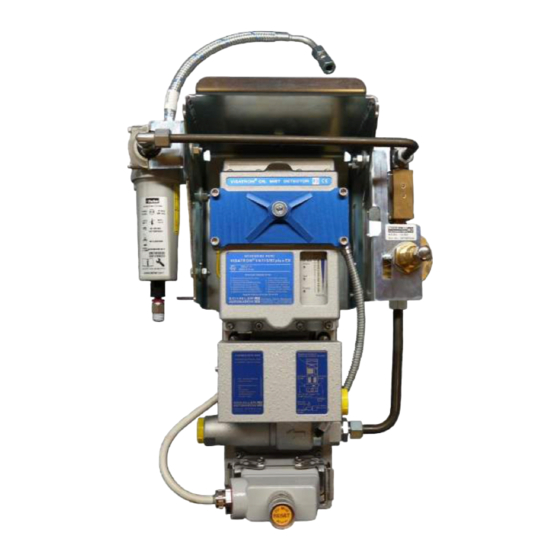
Monitoring device (optional) Filter for air support / water and oil separator The VN115/87plus EX (see Figure 1) is approved to work and use in potentially explosive atmospheres. All devices have a measuring head (2) which includes the optical measuring track under the control cover (3) and a display to give the user all important information for normal operations conditions. - Page 11 The Pre-Alarm will be activated at fix 70% of the Main-Alarm level. To keep the optical track clean, the VN115/87plus EX use clean scavenging air in front of the filter glasses. This air is derived from the compressed air driving the air jet pump.
- Page 12 Optional Siphon block VN180 optional Pipe siphon The best method on a VN115/87plus EX installation to drain the system is to use pipe siphons. Also recommended is the use of siphon blocks. On 2-stroke engines the crankcase and the combustion chambers are separated by stuffing boxes, which let the crankcase be nearly free of blow-by.
- Page 13 Additionally Schaller realized an integration of the VISATRON® VN115/87plus EX into ship automation systems (e.g. Mega-Guard of Praxis Automation). Thus, the VN115/87plus EX is a further contribution to safety at sea. Our goal is to avert damage to assets, personnel and the environment.
-
Page 14: Installation Instructions
"optimum" suction point. The result would be a vast number of holes to be distributed over the entire engine. To find out a safe and economic solution to monitor oil mist SCHALLER AUTOMATION recommends the OMDEA-test (Oil Mist Detection Efficiency Approval). In each case the following rules are recommended. - Page 15 OMDEA (Oil Mist Detection Efficiency Approval). According to the IACS unified requirement M10 the installation drawings have to be approved from engine builder and SCHALLER AUTOMATION. The installations have to be executed in compliance with these drawings and the contents of this manual.
-
Page 16: Pipe Dimensions
The length of exhaust air pipe (outlet of the venturi injector) should be limited to max 4m. If a longer tube is required, please contact Schaller Automation. The inner diameter has to be ≥ 18 mm. U-bends and kinks are forbidden. -
Page 17: Installation Of Pipe Siphons
Operation Manual VISATRON® VN115/87plus EX 06/2016 Page 17 2.1.3 Installation of pipe siphons Figure 7: Pipe siphon Mount the engine wall connection into the G3/4" thread with 110 Nm torque Put the pipe siphon in the hole ... - Page 18 Operation Manual VISATRON® VN115/87plus EX 06/2016 Page 18 Figure 8: Pipe siphon at engine wall Figure 9: Image of pipe siphon Crank case atmosphere Header pipe Flexible hose from suction point Flexible hose to pipe siphon Figure 10: Oil draining principle SCHALLER AUTOMATION D-66440 Blieskastel / Saarland / Germany / Industriering 14 / P.O Box 1280...
-
Page 19: Installation Of The Siphon Block Connection Units
Operation Manual VISATRON® VN115/87plus EX 06/2016 Page 19 2.1.4 Installation of the siphon block connection units Figure 11: Connection unit Consider the following points: Take note of the drilling template (made of paper, included with the connection units) ... -
Page 20: Suction Funnels In The Crankcase Compartment
Operation Manual VISATRON® VN115/87plus EX 06/2016 Page 20 2.1.5 Suction funnels in the crankcase compartment The suction funnels have to be fitted in such a way that flooding by splashing bearing oil or returning piston cooling oil is avoided (see Figure 13). -
Page 21: Compressed Air Connection
Operation Manual VISATRON® VN115/87plus EX 06/2016 Page 21 2.1.6 Compressed air connection The SAB pressure regulator (see Figure 14) is connected to the Air cleaner module. Fine pressure regulator Throttle block Air cleaner connection Air outlet Air flow Air filter Figure 14: Pressure regulator unit 2.1.7 Air cleaner module... -
Page 22: Electrical Installation
Operation Manual VISATRON® VN115/87plus EX 06/2016 Page 22 Electrical installation 2.2.1 VISATRON® VN115/87plus EX device The electrical terminal is inside the socket housing (see Figure 16) on the base plate of the VISATRON® device. The pin assignment is specified in Figure 19. The cable entry points are located on either side. - Page 23 Operation Manual VISATRON® VN115/87plus EX 06/2016 Page 23 Plastic cover Jumper to select the RS485 interface or the 4 -20 mA output Fixing screws of plastic cover Current values of wire break resistors Security seal Figure 17: Rear side of measuring head Second 'Alarm' output and 'Ready' output must be connected to separate channels on vessel’s or power plant’s alarm monitoring system.
- Page 24 Operation Manual VISATRON® VN115/87plus EX 06/2016 Page 24 Shown is non-operated relay condition Description Description 24 Volts DC + 'Pre-alarm' relay 24 Volts DC GND 'Pre-alarm' relay 'Ready' relay closed RS485 B (opt. 4 - 20 mA -) 'Ready' relay open...
-
Page 25: Connection Of Monitoring Devices
Operation Manual VISATRON® VN115/87plus EX 06/2016 Page 25 2.2.2 Connection of monitoring devices As required by IACS UR M10 the OMD device can be connected to Schaller's remote monitoring device Remote Indicator II to monitor the oil mist concentration and the OMD status from a safe location. - Page 26 Operation Manual VISATRON® VN115/87plus EX 06/2016 Page 26 Monitoring device Terminator ● ● ● ● Figure 21: Wiring diagram to connect Remote Indicator II The monitoring device is the bus master and the OMD devices are the slaves. It's necessary to adjust different bus addresses at each slave device. Normally the first OMD device gets the address '1' and so on.
-
Page 27: Schematic Electrical Wiring Diagram
Operation Manual VISATRON® VN115/87plus EX 06/2016 Page 27 2.2.3 Schematic electrical wiring diagram Engine room VN87plus EX Ready and alarm signals Engine control room Engine safety system Optional 4 – 20 mA link RS485 2-wire-bus Remote Indicator II Alarm monitoring system SCHALLER AUTOMATION D-66440 Blieskastel / Saarland / Germany / Industriering 14 / P.O Box 1280... -
Page 28: Commissioning
Operation Manual VISATRON® VN115/87plus EX 06/2016 Page 28 Commissioning CAUTION! Unplug the OMD during welding processes on the engine. Adjusting or checking the suction pressure The suction pressure must be set by adjusting the pressure regulator when the engine is at standstill. Make sure ventilation of the engine room is in operation. -
Page 29: Filling Of Siphon Blocks Vn180 For Vn115/87Plus Ex System With Oil29
Remove U-tube manometer Screw in the removed plug Filling of siphon blocks VN180 for VN115/87plus EX system with oil Press the pump lever of the filling pump (see Figure 26) as many times until first oil drops are coming out. -
Page 30: Filling Of Pipe Siphons For Vn115/87Plus Ex System With Oil
Close the threaded hole with the plug (a small amount oil coming out does not impact the functionality. Clean the siphon block. Continue with the next block. Filling of pipe siphons for VN115/87plus EX system with oil Fitting to flexible hose and oil input Figure 28: Pipe siphon ... -
Page 31: Adjusting The Sensitivity Of The Omd
Operation Manual VISATRON® VN115/87plus EX 06/2016 Page 31 CAUTION! Do not fill in more than 70ml; the excess oil can remove the required oil in the siphon by a physical suction effect through the draining channel. Adjusting the sensitivity of the OMD The detector determines the oil mist concentration by an optical measurement. -
Page 32: Commissioning Check List
Operation Manual VISATRON® VN115/87plus EX 06/2016 Page 32 Commissioning check list Mechanical check Are all suction pipes installed as specified in the installation □ yes / □ no drawing? Are all fittings fastened and tight? □ yes / □ no On installations with siphon blocks: Are all siphon blocks filled □... -
Page 33: Operating Instructions
Operation Manual VISATRON® VN115/87plus EX 06/2016 Page 33 Operating instructions Display After power-on LED 1 is blinking for 30 seconds. The device will show the following display. Error Code Oil Mist Alarm Test Ready Opacity VN 1 15 / 87 plu s E X... - Page 34 Operation Manual VISATRON® VN115/87plus EX 06/2016 Page 34 Blinking Error Code Oil Mist Alarm Test Ready LED off Opacity VN 1 15 / 87 plu s E X SN 50 0 70 0 91 2 3 Figure 32: Device not ready, example of 'Negative pressure out of range' If a device internal error or a system failure occurs the diagnostics system shows the failure condition by a blinking LED on the LED bar.
-
Page 35: Reset Of Oil Mist Alarms
Operation Manual VISATRON® VN115/87plus EX 06/2016 Page 35 Reset of Oil Mist Alarms CAUTION! Use a monitoring device at a safe location (e.g. ECR) to check for the actual oil mist concentration that is requested by the IACS. In case of an Oil Mist Alarm,... -
Page 36: Troubleshooting
Operation Manual VISATRON® VN115/87plus EX 06/2016 Page 36 Troubleshooting Error Description remedy Chapter Negative pressure out of 1. Adjust suction pressure 3.1 page 28 range 2. Exchange air filters 5.3 page 38 3. Clean fresh air bores 5.1 page 37 4. -
Page 37: Clean Fresh Air Bores
Operation Manual VISATRON® VN115/87plus EX 06/2016 Page 37 Clean fresh air bores Fresh air bore Needle of right chamber Figure 34: Cleaning of fresh air bore in the left and the right chambers Clean infrared (IR-) filter CAUTION! Dirty IR-filter glass may cause a loss of sensitivity of the device. -
Page 38: Exchange Air Filters In The Measuring Head
Operation Manual VISATRON® VN115/87plus EX 06/2016 Page 38 Exchange air filters in the measuring head Circlip pliers for Seeger rings Please wear protective glasses! Fresh air filters Figure 36: Exchange of the air filters WARNING! Do not try to clean the filters, use always new ones. -
Page 39: Exchange Measuring Head
Operation Manual VISATRON® VN115/87plus EX 06/2016 Page 39 Exchange measuring head Scavenging air fitting Figure 38: Step 1 is to open the scavenging air fitting Measuring head main connector Figure 39: Step 2 is to unplug the connector SCHALLER AUTOMATION D-66440 Blieskastel / Saarland / Germany / Industriering 14 / P.O Box 1280... - Page 40 Operation Manual VISATRON® VN115/87plus EX 06/2016 Page 40 Fixing screws Figure 40: Step 3 is to unscrew the measuring head To mount the new measuring head execute the 3 steps in reverse order. WARNING! Check the values of the wire break resistors or in case of doubt use the old ones.
-
Page 41: Exchange Bellows And Suspension-System
Operation Manual VISATRON® VN115/87plus EX 06/2016 Page 41 Exchange bellows and suspension-system Step 1 is to dismount the measuring head. Rubber gasket Figure 41: Step 2 is to press out the 4 rubber gaskets with a blunt tool and finally to remove the carrier plate... - Page 42 Operation Manual VISATRON® VN115/87plus EX 06/2016 Page 42 Upper bellow of the suction channel Fixing screws Figure 43: Step 4 is to exchange the 2 bellows if necessary. The bellow is secured by a ring which is fixed by two screws.
-
Page 43: Measuring Head Fuses
Operation Manual VISATRON® VN115/87plus EX 06/2016 Page 43 Measuring head fuses Fuse II Figure 46 Fuse on the rear side of the measuring head The device has two internal fuses. The first is located in the main connector of the measuring head. -
Page 44: Check For Earth Fault Problem
Operation Manual VISATRON® VN115/87plus EX 06/2016 Page 44 Check for earth fault problem Measure contact of Pin Measure contact No. 8 against of Pin No. 7 ground. against ground. If short circuit: If short circuit: problem is problem is outside... - Page 45 Operation Manual VISATRON® VN115/87plus EX 06/2016 Page 45 In case all LED’s remain off despite fuses are ok, perform check as shown in Figure 47. Often it happens during welding work around the engine or in engine room that electrical current of high energy passes through detector and its electrical wiring.
-
Page 46: Maintenance Procedures
Bi-yearly or after 16000 operating hours, whatever comes first An inspection of the entire OMD installation onboard has to be executed by service staff being trained and authorized for this job by Schaller Automation Perform functional test of entire OMD system with smoke See chapter 7.2... -
Page 47: Functional Test
Operation Manual VISATRON® VN115/87plus EX 06/2016 Page 47 Functional test On board test Attention: Before starting the on board test, make sure, the OMD has been maintained according maintenance schedule (chapter 6). If used make sure, that all siphons have to be filled with oil (refer to chapter 2.1.3.) - Page 48 Operation Manual VISATRON® VN115/87plus EX 06/2016 Page 48 Step 3 Add the flexible hose. Step 4 Mount the smoke tube and hand pump and then add them to the flexible hose. Step 5 Use the hand pump to generate smoke (it may...
-
Page 49: Factory Test At Engine Builder With Smoke Generator On Vn115/87Plus Ex Installations
Factory test at engine builder with smoke generator on VN115/87plus EX installations Due to vessels not normally having the equipment and SCHALLER AUTOMATION recommends this procedure only for the factory test by using the SCHALLER smoke generator (see Figure 49). If a smoke generator is available on a vessel, this test can be also performed. - Page 50 Additional pressure measurement on VN115/87plus EX installations Perform the functional and smoke test as shown in the previous chapters 'On board test' and ‘Factory test with smoke generator’.
-
Page 51: Factory Test At Engine Builder With Fog Machine On All Installations50
Operation Manual VISATRON® VN115/87plus EX 06/2016 Page 51 On a VN115/87plus EX installation the tightness of the suction system can be determined by a pressure measurement at the outer siphon blocks or at the end of the header pipes. This siphon block has an additional fitting for a manometer (see Figure 51). To remove the 17 mm lock nut you have to counter the 19 mm nut with a jaw wrench. - Page 52 Page 52 Due to the increasing request of the ship owners and classification societies to test the OMD-System at running engines SCHALLER AUTOMATION recommends now following procedure. The first test must be performed at standstill to secure, that the engine is well protected by the OMD system.
-
Page 53: Optional Spare Parts And Accessories
Description Quantity per OMD 150516 Service box series VN87plus EX 12601 Measuring head VN115/87plus EX; 33k (wire break resistor); RS485; sensitivity level 4 12602 Measuring head VN115/87plus EX; 24k; 4- 20mA; sensitivity level 4 12603 Measuring head VN115/87plus EX; 3k; 4- 20mA;... - Page 54 Operation Manual VISATRON® VN115/87plus EX 06/2016 Page 54 365280 Gasket G½" oil proof Table 4: Optional Spare parts Part-No. new Part-No. old Description 150516 Service box series VN87plus EX 151780 VN-Smoke Test-Box 180080 Manual DVD series VN87plus EX 151072 10001...
-
Page 55: Optional Service Box
Operation Manual VISATRON® VN115/87plus EX 06/2016 Page 55 Optional Service Box Figure 56: Optional Service box 150516 SCHALLER AUTOMATION D-66440 Blieskastel / Saarland / Germany / Industriering 14 / P.O Box 1280 Tel. +49(0)6842-508-0 / Fax -260 / eMail: info@schaller.de / www.schaller.de... - Page 56 Operation Manual VISATRON® VN115/87plus EX 06/2016 Page 56 Item Description Quantity For spares Service box VN87plus EX content list 180509 Scavenging air filters 365197 / 10042 Cleaning needle 190003 / 10135 Fuse 2A semi time lag 436551 / 10973 Screwdriver 3 mm...
-
Page 57: Vn-Smoke Test Box
Operation Manual VISATRON® VN115/87plus EX 06/2016 Page 57 VN-Smoke Test Box Figure 57: VN-Smoke Test-Box 151780 SCHALLER AUTOMATION D-66440 Blieskastel / Saarland / Germany / Industriering 14 / P.O Box 1280 Tel. +49(0)6842-508-0 / Fax -260 / eMail: info@schaller.de / www.schaller.de... - Page 58 Operation Manual VISATRON® VN115/87plus EX 06/2016 Page 58 Item Description Quantity For Spares Hand pump 450421 Smoke tube 1 (6 pcs.) 272059 Adapter flexible hose f. smoke tubes 270710 Connection QS-G¼-6 270704 Flexible hose D6 366655 Table 7: Contents of VN-Smoke Test-Box 151780 SCHALLER AUTOMATION D-66440 Blieskastel / Saarland / Germany / Industriering 14 / P.O Box 1280...
-
Page 59: Technical Data
LED-bar with 14 LED's 1 green Ready LED 1 red High Oil Mist Alarm LED 1 red Test LED Suction pipes VN115/87plus EX ø 22 x 2 x max. 9m Pipe connections VN115/87plus EX 2 x G3/4 Venturi injector connections NTP/BSP/G1/2A... - Page 60 (directive 94/9/EC) II (2G) [Ex op is IIB T4 Gb] Table 8: Technical data Figure 58: Mechanical dimensions of VN115/87plus EX: side view SCHALLER AUTOMATION D-66440 Blieskastel / Saarland / Germany / Industriering 14 / P.O Box 1280 Tel.
- Page 61 Operation Manual VISATRON® VN115/87plus EX 06/2016 Page 61 Figure 59: Mechanical dimensions of VN115/87plus EX: top view Figure 60: Drilling template of the OMD base plate SCHALLER AUTOMATION D-66440 Blieskastel / Saarland / Germany / Industriering 14 / P.O Box 1280 Tel.
-
Page 62: Service Partners
Operation Manual VISATRON® VN115/87plus EX 06/2016 Page 62 10 Service Partners Schaller Automation maintains a worldwide network of service partners in following countries: Argentina Latvia Australia Lithuania Bahrain Mauritania Belgium Mexico Belize Morocco Bolivia Netherlands Brazil Nicaragua Canada Norway Cape Verde Islands...
Need help?
Do you have a question about the VN115/87plus EX and is the answer not in the manual?
Questions and answers